Nortec RS Series Installation Manual
Steam humidifier
Hide thumbs
Also See for RS Series:
- Installation, operation and maintenance manual (72 pages) ,
- Quick start installation manual (8 pages)

Related Manuals for Nortec RS Series


Summary of Contents for Nortec RS Series
- Page 1 INSTALLATION MANUAL Steam humidifier Nortec RS Humidification and Evaporative Cooling...
- Page 2 Nortec Humidity Ltd., except to the extent required for installation or maintenance of recipient's equipment. Liability Notice Nortec Humidity Ltd. does not accept any liability due to incorrect installation or operation of the equipment or due to the use of parts/components/equipment that are not authorized by Nortec Humidity Ltd. Copyright Notice Copyright 2015, Nortec Humidity Ltd.
-
Page 3: Table Of Contents
5.7.2 Admissible Control Signals Electrical Installation 5.8.1 Notes on Electrical Installation 5.8.2 Wiring Diagram Nortec RS - Small and Medium Units 5.8.3 Wiring Diagram Nortec RS - Large Units 5.8.4 Installation Work – External Connections 5.8.4.1 Fuses "F3" Voltage Supply 5.8.5... - Page 4 Contents...
-
Page 5: Introduction
Further information on options and accessories can be obtained in their respective instructions. This installation manual is restricted to the installation of the Nortec RS steam humidifier and is meant for well trained personnel being sufficiently qualified for their respective work. - Page 6 Please safeguard this installation manual in a safe place, where it can be immediately accessed. If the equipment changes hands, the documentation must be passed on to the new operator. If the documentation gets misplaced, please contact your Nortec representative for replacement. Introduction...
-
Page 7: For Your Safety
For Your Safety General Every person, who is in charge of the installation work on the Nortec RS must have read and understood this installation manual and the Nortec RS operation manual before carrying out any work. Knowing and understanding the contents of the installation manual and the operation manual is a basic requirement for protecting personnel against any kind of danger, to prevent faulty operation, and to operate the unit safely and correctly. - Page 8 Preventing unsafe operation All persons working with the Nortec RS are obliged to report any alterations to the unit, modifications, or unsafe issues that may affect safety to the owner without delay and to secure the Nortec RS against accidental power-up.
-
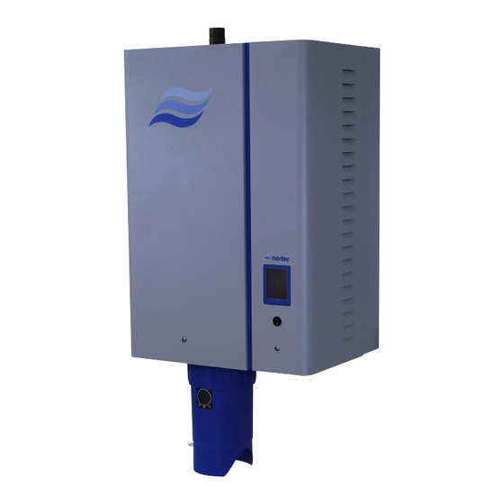
Page 9: Product Overview
Product Overview Models Overview Nortec RS steam humidifiers are available in different housing sizes (S, M and L) with different heating voltages and steam capacities ranging from 10 lbs/hr up to a maximum of 180 lbs/hr (5 ... 80 kg/h). -
Page 10: Units Large ("L")
3.1.2 Units Large ("L") 208 V/1~ 240 V/1~ 480 V/1~ 600 V/1~ 208 V/3~ 240 V/3~ 480 V/3~ 600 V/3~ Housing Nortec size lb/hr (kg/hr) lb/hr (kg/hr) lb/hr (kg/hr) lb/hr (kg/hr) lb/hr (kg/hr) lb/hr (kg/hr) lb/hr (kg/hr) lb/hr (kg/hr) ––... -
Page 11: Identification Of The Unit
Identification of the Unit The identification of the unit is found on the specification label. Type designation Serial number MODEL: RS 010 SER: XXXXXXX Electrical supply requirements VOLTS: PHASE: AMPS: 17.8 Current draw Power consumption MAX: Max. external fuse Circuit Protection 11/14 Month/Year Fig. -
Page 12: Product Designation
The product designation and the most important unit data are found on the specification label fixed on the right side of the Nortec RS. Notes regarding the specification label can be found in the Nortec RS operation manual. Key model designation... -
Page 13: Options
1x BAC-BTL-IP PCB to provide BTL certified BACnet IP. LonWorks board 1x LON Supplementary board to connect the Nortec RS to a building management system via LonWorks. Mounting bar Provides two mounting bars which fit into each other for wall mounting. One bar is fastened... - Page 14 Nortec RS Height extension profiles for 1x MR-E mounting rack basic ** (N/A for RS 90 large unit) Height extension profiles for mounting rack. Adjustable profiles for mounting rack basic ** 1x MR-A (N/A for RS 90 large unit) Profiles with screw feet for levelling the mounting rack.
-
Page 15: Receiving And Storage
Check packing slip to ensure all parts have been delivered. All material shortages are to be reported to your Nortec supplier within 48 hours after receipt of the goods. Nortec Humidity Ltd. assumes no responsibility for any material shortages beyond this period. -
Page 16: Mounting And Installation Work
DANGER! Danger of electric shock! The Nortec RS is mains powered. Live parts may be exposed when the unit is open. Touching live parts may cause severe injury or danger to life. Prevention: The Nortec RS must be connected to the mains only after all mounting and installation work has been completed, all installations have been checked for correct workmanship and the unit is closed and properly locked. -
Page 17: Installation Overviews
Installation Overviews Typical installation for duct humidification Humidity sensor or humidity controller u c t i b s t r ( 3 m Return duct o w n n y o 4 f t n k n . 9 . 8 t o a i s u High limit humidistat... - Page 18 Typical installation for room humidification Blower Pack (mounted separated from the steam humidifier) Steam line – As short as possible – Adequate upslope (min. 10°)/downslope (2.0°) – No restrictions Condensate line – Condensate trap at the lowest point – Min. downslope 1.2° –...
-
Page 19: Mounting The Unit
Mounting the Unit 5.3.1 Notes on Locating the Unit 0 " 0 " Fig. 6: Minimal clearances to be observed Housing Small Medium Large Housing dimensions 16.5" (420) 20.9" (530) 29.4" (1000) in inch (mm) 14.6" (370) 16" (406) 16" (406) 26.4"... - Page 20 The steam humidifier Nortec RS must only be installed in rooms with a floor drain. CAUTION! If for some reason the Nortec RS must be installed in a location without floor drain, it is mandatory to provide a leakage monitoring device to safely interrupt the water supply in case of leakage.
-
Page 21: Mounting The Humidifier
Mark the mounting hole locations "A" and "B" on 2×4 wooden studs (or equivalent) in the mounting surface, as shown, and mount the Nortec RS unit using 1/4 × 2 in lag bolts and washers. Overview standard mounting single units Small and Medium... - Page 22 Overview standard mounting single units Large Dimension Housing size Large "a" in inch/mm 6.5" (164.0) "b" in inch/mm 16.8" (426.0) "c" in inch/mm 4.6" (117.2) "d" in inch/mm 16.0" (406.4) Weights Housing size Large Net weight in lb/kg 179 (81.0) Operating weight in lb/kg 291 (132.0) Fig.
- Page 23 Mounting procedure standard mounting 1. Mark the attachment points "A" and "B" at the desired position in the mounting surface with the help of a level. 2. Install 1/4 × 2 in lag bolts and washers at attachment points "A". Allow the heads of the bolts to extend 1/4 in (5 mm) from the mounting surface so that the humidifier can be hung on the bolts.
-
Page 24: Wall Support Mounting (Option)
Mark the mounting hole locations "A" on 2×4 wooden studs (or equivalent) in the mounting surface, as shown, and mount the wall support for the Nortec RS unit using 1/4 × 2 in lag bolts and washers. Overview wall support mounting single units Small and Medium... - Page 25 Mounting overview wall support mounting single units Large Dimension Housing size Large "a" in inch/mm 10.4" (263.5) "b" in inch/mm 16.0" (406.4) "c" in inch/mm 4.6" (117.2) Weights Housing size Large Net weight in lb/kg 179 (81.0) Operating weight in lb/kg 291 (132.0) Fig.
-
Page 26: Inspecting The Installed Unit
Procedure 1. Mark the attachment points "A" for the wall support at the desired position with the help of a level. 2. Attach the wall support to 2×4 wooden studs (or equivalent) in the mounting surface with 1/4 × 2 in lag bolts and washers. -
Page 27: Steam Line Installation
Steam Line Installation 5.4.1 Overview Steam Line Installation for Duct Humidification u c t i b s t r ( 3 m o w n Return duct n y o 4 f t n k n . 9 . 8 t o a i s u m i n... -
Page 28: Installing The Steam Distributors
Blower Pack (mounted remotely from the steam humidifier) Steam line – As short as possible – Adequate upslope (min. 10°)/downslope (2.0°) Condensate line – No restrictions – Min. downslope 1.2° – Condensate trap at the lowest point – No restrictions –... -
Page 29: Positioning And Mounting The Blower Packs
5.4.3 Positioning and Mounting the Blower Packs The blower packs can either be mounted directly on the humidifier or separately above the humidifier to the wall. To allow the steam coming from the blower pack to spread out evenly, without condensing on obstacles (ceilings, joists, pillars, etc.), the following minimum dimensions must be observed when selecting the location for the blower pack. -
Page 30: Installing The Steam And Condensate Lines
Installations notes – Use original steam and condensate hose from your Nortec representative or solid steam pipes from copper (MED-L) or stainless steel (min. AISI 304) exclusively. Steam and condensate lines of other material may cause undesired operational malfunctions. For installations with reverse osmosis or de-ionized water supply, do not use copper steam lines. - Page 31 0.22 Notes: * The use of steam line other than copper, stainless steel tube, or Nortec supplied steam line will void the warranty and may adversely affect the operation of the humidifier. ** Long steam runs affect accuracy of humidifier and its ability to quickly respond to changes in demand.
- Page 32 Installation examples Ømin. 8" (Ømin. 200 mm) Fig. 13: Steam distributor mounted more than 20" (500 mm) above the top edge of the humidifier Mounting and Installation Work...
- Page 33 Ømin. 8" (Ømin. 200 mm) Ensure adequate cooling according to local codes Obstacle Ømin. 8" (Ømin. 200 mm) Ømin. 8" (Ømin. 200 mm) Ensure adequate cooling according to local codes Install condensate drain (full size T) at the lowest point. Ensure proper slope is maintained for the steam lines upstream and downstream of the T.
- Page 34 Steam line must be insulated over the entire length! Ømin. 8" (Ømin. 200 mm) Fig. 15: Steam line with solid piping and insulation Mounting and Installation Work...
-
Page 35: Common Steam And Condensate Line Errors
5.4.5 Common Steam and Condensate Line Errors Wrong Correct Steam line not led at least 12" (300 mm) perpendicularly Lead steam line at least 12" (300 mm) perpendicularly up- upwards before first bend (forming of condensate). wards before first bend. Minimum bend radius of steam hose/solid steam line not The minimum bend radius of 12"... -
Page 36: Inspecting The Steam Installation
Are the outlet orifices at right angles to the air flow for horizontal installation, or at 45 degree angle for vertical installation? – Steam hose Steam hose material: copper (potable water only), stainless steel or Nortec plastic hose? Maximum length, as per table shown in Section 5.4.4? Minimum bend radius of 12"... -
Page 37: Water Installation
Water Installation 5.6.1 Overview Water Installation Water drain connector ø1.18" (ø30 mm) Water supply connector G 3/4" Adapter G 3/4" / 1/2" NPT G 3/4" Adapter G 3/4" / 1/2" NPT (supplied with O-ring and gasket) 1/2" NPT Water supply pipe Filter valve or Drain line: Shut-off valve and 5 micron filter... -
Page 38: Notes On Water Installation
For mains pressures > 80 psi (5 bar), the connection must be made via a pressure reducing valve (adjusted to 30 psi (2 bar)). For mains pressures <30 psi (2 bar) please contact your Nortec supplier. Notes on water quality: –... -
Page 39: Inspecting The Water Installation
5.6.3 Inspecting the Water Installation Check the following topics: – Water supply Has shut-off valve and (optionally) 5 micron water filter been installed? Has acceptable water pressure (30 - 80 psi (2 to 5 bar)) and acceptable water temperature (without drain water cooling: 34 - 77ºF (1 - 25ºC) been observed? Is the minimum inside diameter of the water supply pipe maintained throughout the entire length? Are all components and pipes properly secured and are all threaded connections securely tight- ened? -
Page 40: Notes On Humidity Control Systems/Humidity Control
Notes on Humidity Control Systems/Humidity Control 5.7.1 Control Device Locations The following schematic describes a potential system setup with respect to control devices. φ φ φ φ φ Fig. 18: System Setup Schematic Humidistat Humidity sensor High limit humidistat Air proving switch Notes: •... -
Page 41: Electrical Installation
DANGER! Danger of electric shock The Nortec RS is mains powered. Live parts may be exposed when the unit is open. Touching live parts may cause severe injury or danger to life. Prevention: The Nortec RS unit must be connected to the mains only after all mounting and installa- tion work has been completed, all installations have been checked for correct workmanship and the unit is closed and properly locked. -
Page 42: Wiring Diagram Nortec Rs - Small And Medium Units
Jumper, install if no blower pack is connected Jumper for activating the terminating resistor for Modbus network (Jumper must be connected, if Nortec RS is the last unit in the Modbus network) Jumper for activating Modbus or BACnet MSTP communication via RS485 interface (J6). -
Page 43: Wiring Diagram Nortec Rs - Large Units
Jumper for activating the terminating resistor for Modbus network Ohmic humidity ontroller (passive), set jumper JP2 to 5V (Jumper must be connected, if Nortec RS is the last unit in the On/Off humidity controller, set jumper JP2 to 24V Modbus network) -
Page 44: Installation Work - External Connections
5.8.4 Installation Work – External Connections Connecting the external safety chain The potential-free contacts of external moni t or ing de- vices (e.g. ventilation interlock, safety high limit humidis- tat, airflow monitor, etc.) are connected in series (safety chain "K2") to the terminals "1" and "2" of the control terminal block "XE2"... - Page 45 Ohmic humidity controller (passive) The signal cable of an ohmic humidity controller (140Ω...10kΩ) is to be connected according to the wiring diagram to the terminals "3" (GND), "4" (IN) and "6" (V+) of the control terminal block "XE2" inside the Driver board control compartment.
- Page 46 Control compartment a warning is indicated. – "Steam": This relay closes as soon as the Nortec RS humidi- fies. – "Unit on": This relay closes as soon as the voltage supply to the control compartment of the Nortec RS is switched on.
- Page 47 Connecting the voltage supply The voltage supply (L1, L2, L3 and GND or L1 and) is to be connected in accordance with the wiring diagram to the corresponding terminals of the main contac- tor in the control compartment. The earth conductor L1 L2 is to be connected to the earth terminal right beside the main contactor.
-
Page 48: 5.8.4.1 Fuses "F3" Voltage Supply
5.8.4.1 Fuses "F3" Voltage Supply 208 V/1~/50...60 Hz 240 V/1~/50...60 Hz 480 V/1~/50...60 Hz 600 V/1~/50...60 Hz RS 10 17.8 RS 15 34.7 13.3 11.1 RS 20 10.8 10.8 10.7 22.3 10.7 17.8 RS 30 RS 45 –– –– –– ––... -
Page 49: Inspecting The Electrical Installation
5.8.5 Inspecting the Electrical Installation Check the following points: Do the supply voltages for heating and control voltage comply with the relevant voltages stated on the specification label? Is the high voltage supply correctly fused? Are all components correctly connected according to the wiring diagram? Are all connecting cables fastened? Are the connecting cables free of tension (passed through cable glands?) Does the electric installation meet the applicable local regulations for electric installations? -
Page 50: Appendix
Appendix Unit Dimensions 6.83 (173.5) CONDENSATE OUT 2.82 (71.7) ø 0.31 (8) 2X MARKED “A” STEAM OUT 4.87 (123.8) ø 1.77 (45) 3.16 (80.2) 1.38 12.00 (304.8) (35) 16.54 (420) 2.27 2.27 (57.6) 12.00 (304.8) 14.33 (364) 0.28 (7) (57.6) 2.24 (57) WATER FILL Shown with optional scale tank... - Page 51 7.16 (181.8) CONDENSATE OUT 6.44 (163.5) ø 0.31 (8) 2.43 (61.8) 2X MARKED “A” STEAM OUT ø 1.77 (45) 3.48 (88.5) 1.38 (35) 16.00 (406.5) 20.87 (530) 2.43 (61.8) 16.00 (406.5) 2.43 15.98 (406) 0.28 (7) (61.8) 2.24 (57) WATER FILL NPT 1/2"...
- Page 52 20.49 (520.5) 16.49 (418.8) CONDENSATE OUT 6.44 (163.5) ø 0.31 (8) 2.43 (61.8) 4X MARKED “A” 178.8 535.8 STEAM OUT ø 1.77 (45) 39.37 (1000) 15.98 (406) 0.28 (7) 4.61 (117) 2.76 (70) 16.00 (406.5) 16.00 (406.5) 4.21 (107) WATER FILL NPT 1/2"...
- Page 53 Notes...
- Page 54 Notes...
- Page 55 Warranty Nortec Humidity Inc. and/or Nortec Humidity Ltd. (hereinafter collectively referred to as THE COMPANY), warrant for a period of two years after installation or 30 months from manufacturer’s ship date, whichever date is earlier, that THE COMPANY’s manufactured and assembled products, not otherwise expressly warranted, are free from defects in material and workmanship.
- Page 56 U.S.A. 826 Proctor Avenue Ogdensburg, NY 13669 CANADA 2740 Fenton Road Ottawa, Ontario K1T 3T7 TEL: 1.866.NORTEC1 FAX: 613.822.7964 EMAIL: nortec@humidity.com WEBSITE: www.humidity.com...
Need help?
Do you have a question about the RS Series and is the answer not in the manual?
Questions and answers