Table of Contents
Advertisement
FAILURE TO READ AND UNDERSTAND THE FOLLOWING
INSTRUCTIONS MAY CAUSE YOU UNNECESSARY COM-
PLICATIONS IN THE INSTALLATION OR OPERATION OF
THIS EQUIPMENT.
More Than Air. Answers.
Online answers: http://www.ingersollrandproducts.com
PHONE: 1-800-AIR-COMP (1-800-247-2667)
PSG Series
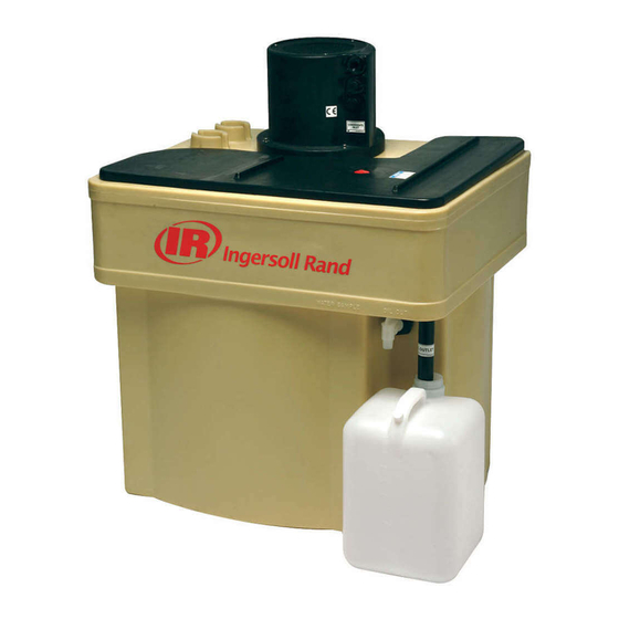
OIL/WATER SEPARATORS
INSTALLATION, OPERATION,
MAINTENANCE MANUAL AND
PARTS LIST
: 38471157
C.C.N.
: B
REV.
DATE : June 2011
Advertisement
Table of Contents

Summary of Contents for Ingersoll-Rand PSG Series
- Page 1 PSG Series OIL/WATER SEPARATORS INSTALLATION, OPERATION, MAINTENANCE MANUAL AND PARTS LIST FAILURE TO READ AND UNDERSTAND THE FOLLOWING INSTRUCTIONS MAY CAUSE YOU UNNECESSARY COM- PLICATIONS IN THE INSTALLATION OR OPERATION OF THIS EQUIPMENT. : 38471157 C.C.N. More Than Air. Answers.
- Page 2 (at manufacturer’s option) of unaltered products returned to manufacturer within stated period. In order to process a claim, Ingersoll-Rand must get from the customer a proof of purchase (date of purchase, invoice number). In no event, shall Ingersoll-Rand be liable for business interrup- tions, loss of profits, personal injury, costs of delay or any other special, indirect, incidental, or consequential losses, cost, or damages.
-
Page 3: Table Of Contents
TABLE OF CONTENTS 1.0 GENERAL 2.0 HOW IT WORKS 3.0 INSTALLATION INSTRUCTIONS 3.1 Placement 3.2 Filter Preparation 3.3 Water Outlet Plumbing Preparation 3.4 Condensate Inlet Preparation 3.5 Collection Manifold Guidelines 3.6 Priming The System 3.7 Oil Outlet Tube Adjustment 3.8 Sample Testing 3.9 Commissioning 4.0 OPERATION INSTRUCTIONS 5.0 MAINTENANCE INSTRUCTIONS... - Page 4 Performance Statement for Ingersoll Rand Polysep PSG Series The Polysep PSG Series is designed to separate a wide variety of compressor lubricants from compressor condensate. PSG separators use gravity separation to float and remove lubricants which separate easily and do not emulsify. Stable emulsions, such as polyglycol based lubricants, are broken and removed by the absorption filter modules incorporated in the PSG.
-
Page 5: General
1.0 GENERAL the separation process. It also prevents the dirt, rust and scale from leaving the Sediment Chamber. The separator provides an environment where (2) Processing: Both the Oil and Water enter the the small percentage of an insoluble lubricant can Vessel through exit holes in the Sediment Chamber. -
Page 6: Installation Instructions
3.0 INSTALLATION 4. Reinstall the pre-wetted Pre-Adsorber and Adsorption Module. INSTRUCTIONS Note: For ease of installation, roll the Adsorption Module on the floor to elongate it. Pick-up the module 3.1 PLACEMENT in both hands and carry horizontally. Position the end of the module at the top of the chamber and gently tip The separator must be installed on a flat and level up and slide into the chamber. -
Page 7: Priming The System
3. Use a chemical and corrosion resistant piping and 3. Clean the Sample Jar thoroughly after sampling, fittings, such as PVC or copper. empty and dry. 4. Locate the manifold at an elevation above the 4. Store the Sample Jars in the Placement Wells separator or Flow Divider (CCN 2204432). -
Page 8: Operation Instructions
3. Lift up the Diffuser and move it out of the way so provides fluid testing services. To learn more about you can remove the Sediment Chamber. the services, please contact your local Ingersoll-Rand 4. Grasp the edges of the Sediment Chamber and service provider. -
Page 9: Sizing
6.0 SIZING Cold Climate: 60 F (15 C), 60% RH Compressor Capacity (CFM) IR Model Screw Compressors Reciprocating Compressors Turbine Oil Synthetic Oil Polyglycol Ester Turbine Oil Diester PS-7 PSG-15 PSG-30 1,700 1,275 1,700 1,275 PSG-60 3,400 2,550 3,400 2,550 1,700 1,445 5,100... -
Page 10: Troubleshooting
7.0 TROUBLESHOOTING Trouble Probable Cause/Remedy Water in Oil Container Unit is not on a level surface. • Level area as noted in “PLACEMENT” section. Oil Outlet Tube is set too low allowing water to exit with the oil. • Refer to “OIL OUTLET TUBE ADJUSTMENT” section for details. A large condensate surge will elevate the water level above the Oil Outlet Tube and allow water to escape before level adjusts. -
Page 11: General Data
8.0 GENERAL DATA... - Page 12 9.0 PARTS PSG-60/90 PSG-15/30 PSG PARTS TABLE Part Description PSG-15 PSG-30 PSG-60 PSG-90 Diffuser Cover Ring 38339875 38465662 38465662 38465662 Diffuser Pad Separation Filter 38339057 38465712 38465761 38469052 Adsorption Module Pre-Adsorption Pad Diffuser Assembly 38339891 38465670 38465670 38465670 Vessel 38339966 38465720 38465753 38465688...


Need help?
Do you have a question about the PSG Series and is the answer not in the manual?
Questions and answers