Table of Contents
Advertisement
Quick Links
Advertisement
Table of Contents

Related Manuals for Lindsay Broadband LBDG-TC4400-4PPoE-50W


Summary of Contents for Lindsay Broadband LBDG-TC4400-4PPoE-50W
- Page 1 LBDG-TC4400-4PPoE-50W LBDG-TC4400-4PPoE-50W DOCSIS 3.1 Gateway Installation Guide...
-
Page 2: Replacement Parts
Unauthorized substitutions may result in fire, electric shock or other hazards. SERVICE DEPOT: Canada: Lindsay Broadband Inc., 2035 Fisher Dr., R.R. #5 Peterborough, Ontario K9J 6X6 (705) 742-1350... -
Page 3: General Description
LBDG-TC4400-4PPoE-50W 1.1 Introduction This manual is written to help service perso nnel understand and install the Lindsay 50W DOCSIS 3.1 Gateway. This first section gives a block diagram and a full product description. The remaining sections provide component identification diagrams,... -
Page 4: Major Components
LBDG-TC4400-4PPoE-50W 1.3 Housing A rugged die cast aluminum housing of clamshell design is used. Externally, the housing has installation mounts and three connectors: • A type F test point connector. Signal leve ls read at this connector are -20dB relative to the cable modem F port. - Page 5 LBDG-TC4400-4PPoE-50W • A Test Point provides -20dB coupling of forward and reverse power at the modem port. • Plug-in SVP type surge protection. • Socket for optional solid state, crowbar type surge protection. • A power-interrupt to disconnect AC power.
-
Page 6: Section 3 Installation
The DOCSIS Gateway can be connected to any power passing tap, splitter, or coupler. 3.1 Pre-Installation Upon receipt of the LBDG-TC4400-4PPoE-50W, inspect the carton for any external damage. If damage is present , inspect the Gateway exterior for damage. Report any apparent damage to the shipping agent and the Lindsay Broadband sales office. -
Page 7: Installation Diagrams
LBDG-TC4400-4PPoE-50W 3.2 Installation Diagrams Strand Mount Strand Mount with Hanger Brackets 3.3 Power Requirements The DOCSIS 3.1 Gateway can be connected to any power passing tap, splitter or coupler. A DOCSIS Gateway delivering 50 Watts to an IP device will draw up to 1 Amp from a 90V supply. - Page 8 LBDG-TC4400-4PPoE-50W 3.4 Installation 1. Pull the AC interrupt in the power passing tap or coupler. 2. Using the diagrams in this section as a guide, mount the Gateway at its final location. If using hanger brackets, the existing strand clamps should be left in place to act as spacers allowing the same bolts to be used.
-
Page 9: Attaching The Ethernet Cable
LBDG-TC4400-4PPoE-50W 11. Tape all connections to reduce moisture intake. 3.5 Attaching the Ethernet Cable 1. Remove the thin nut from the feed-thru assembly. This nut is only used to hold the rubber gasket in place and can be discarded. 2. Loosen the compression nut completely. -
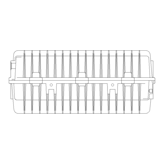
Page 10: Top View
LBDG-TC4400-4PPoE-50W SECTION 4 LBDG-TC4400-4PPoE-50W HOUSING DIMENSIONS 4.1 Housing Dimensions TOP VIEW 16.375” 9.750” RIGHT END SIDE VIEW 6.375” SIDE VIEW FROM HINGE 1.875” 1.250”... - Page 11 LBDG-TC4400-4PPoE-50W 4.2 Table of Specifications Lindsay LBDG-TC4400-4PPoE-50W Gateway Specifications Cable Modem Band Plans DOCSIS (Annex B), Euro-DOCSIS (Annex A) Network Configuration and Management TFTP, SNMP (V1, V2c, V3), Telnet, HTTP RF Input Sensitivity +15 to -15dBmV 75 Ω Input Impedance...
Need help?
Do you have a question about the LBDG-TC4400-4PPoE-50W and is the answer not in the manual?
Questions and answers