
Related Manuals for Lindsay Broadband LBDG-100-DC


Summary of Contents for Lindsay Broadband LBDG-100-DC
- Page 1 LBDG-100-DC LBDG-100-DC Strand Mount DOCSIS 3.0 Gateway with DC Power Output Installation Guide...
- Page 2 LBDG-100-DC IMPORTANT SAFETY AND INSTALLATION WARNINGS WARNING: ATTEMPT SERVICE THIS PRODUCT YOURSELF AS OPENING OR REMOVING COVERS MAY EXPOSE YOU TO DANGEROUS VOLTAGES OR OTHER HAZARDS. REFER ALL SERVICING TO QUALIFIED SERVICE PERSONNEL. MOUNTING: Mount this product only as described in the installation instructions, otherwise it may fall causing serious personal injury and/or damage to the device.
- Page 3 Unauthorized substitutions may result in fire, electric shock or other hazards. SERVICE DEPOT: Canada: Lindsay Broadband Inc., 2035 Fisher Dr., R.R. #5 Peterborough, Ontario K9J 6X6 (705) 742-1350...
-
Page 4: General Description
1.1 Introduction This manual is written to help service perso nnel understand and install the Lindsay LBDG-100-DC DOCSIS 3.0 Gateway with DC Power Output. This first section gives a block diagram and a full product description. The remaining sections provide component identification diagrams, installation instructions, and specifications. -
Page 5: Major Components
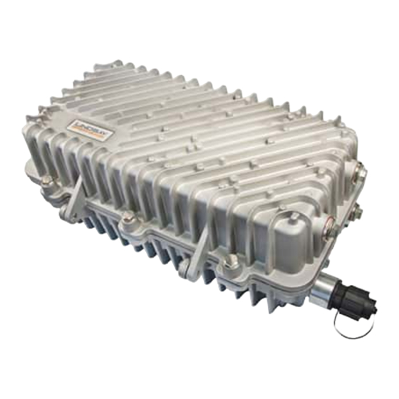
LBDG-100-DC 1.3 Housing A rugged die cast aluminum housing with a clamshell design is used. Externally, the housing has installation mounts and four connectors: • A 5/8-24 threaded bushing for KS type connection to the HFC network. • A type F test point connector. Signal levels read at this connector are -20dB relative to the cable modem F port. - Page 6 LBDG-100-DC • Plug-in SVP type surge protection. • Socket for optional solid state, crowbar type surge protection. • A power-interrupt to disconnect AC power. SECTION 2 COMPONENTS IDENTIFICACION CABLE WEATHER SURGE INTERRUPT MODEM SEAL ARRESTOR HFC INPUT ETHERNET GigE (RJ45) UPSTREAM &...
-
Page 7: Section 3 Installation
LBDG-100-DC SECTION 3 INSTALLATION Installation of the LBDG-100-DC DOCSIS 3.0 Gateway is similar to the installation of a line extender or any other piece of CATV equipment. The DOCSIS Gateway can be connected to a power-passing coupler or splitter. Call Lindsay Broadband for the recommended power insertion device for your application. -
Page 8: Installation Diagrams
LBDG-100-DC 3.2 Installation Diagrams Strand Mount Strand Mount with Hanger Brackets 3.3 Power Requirements The DOCSIS 3.0 Gateway with DC Power Output can be connected to any power passing splitter or coupler. The following formula can be used to calculate the current draw for your installation:... - Page 9 LBDG-100-DC 3.4 Output Receptacle Wiring...
- Page 10 LBDG-100-DC 3.5 Installation 1. Pull the AC interrupt in the power-passing coupler or splitter. 2. Using the diagrams in this section as a guide, mount the Gateway at its final location. If using hanger brackets, the existing strand clamps should be lef t in place to act as spacers allowing the same bolts to be used.
-
Page 11: Attaching The Ethernet Cable
LBDG-100-DC 12. Tape all connections to reduce moisture intake. 3.6 Attaching the Ethernet Cable The external RJ45 connector on the Lindsay LBDG-DC Gateway provides an IP68 weather-tight connection. A cable that is pre-terminated with an RJ45 connector can be used. No tools are required. - Page 12 LBDG-100-DC SECTION 4 LBDG-100-DC HOUSING DIMENSIONS 4.1 Housing Dimensions TOP VIEW 16.375” 9.750” RIGHT END SIDE VIEW 6.375” SIDE VIEW FROM HINGE 1.875” 1.250”...
- Page 13 LBDG-100-DC 4.2 Table of Specifications Lindsay LBDG-100-DC Gateway with DC Power Supply Specifications Cable Modem Band Plans DOCSIS (Annex B) Network Configuration and Management TFTP, SNMP (V1, V2c, V3), Telnet, HTTP Input Impedance 75 Ω Privacy BPI+ Downstream Modulation 64 or 256 QAM...
- Page 14 LBDG-100-DC...
Need help?
Do you have a question about the LBDG-100-DC and is the answer not in the manual?
Questions and answers