
Related Manuals for Lindsay Broadband LBDG-250-DC-8200-1


Summary of Contents for Lindsay Broadband LBDG-250-DC-8200-1
- Page 1 LBDG-250-DC-8200-1 LBDG-250-DC-8200-1 Strand Mount DOCSIS 3.1 Gateway With DC Power Output Installation Guide...
- Page 2 LBDG-250-DC-8200-1 IMPORTANT SAFETY AND INSTALLATION WARNINGS WARNING: ATTEMPT SERVICE THIS PRODUCT YOURSELF AS OPENING OR REMOVING COVERS MAY EXPOSE YOU TO DANGEROUS VOLTAGES OR OTHER HAZARDS. REFER ALL SERVICING TO QUALIFIED SERVICE PERSONNEL. MOUNTING: Mount this product only as described in the installation instructions, otherwise it may fall causing serious personal injury and/or damage to the device.
-
Page 3: Replacement Parts
Unauthorized substitutions may result in fire, electric shock or other h azards. SERVICE DEPOT: Canada: Lindsay Broadband Inc., 2035-2 Fisher Dr. Peterborough, Ontario K9J 6X6 (705) 742-1350... - Page 4 LBDG-250-DC-8200-1 1.1 Introduction This manual is written to help service perso nnel understand and install the Lindsay LBDG-250-DC-8200-1 DOCSIS 3.1 Gateway with DC Power Output. This first section gives a block diagram and a full product description. remaining sections provide component identification diagrams, installat ion instructions, and specifications.
- Page 5 LBDG-250-DC-8200-1 1.3 Housing A rugged die cast aluminum housing with a clamshell design is used. Externally, the housing has installation mounts and four connectors: • A 5/8-24 threaded bushing for KS type connection to the HFC network. • A type F test point connector. Signal levels read at this connector are -20dB relative to the cable modem F port.
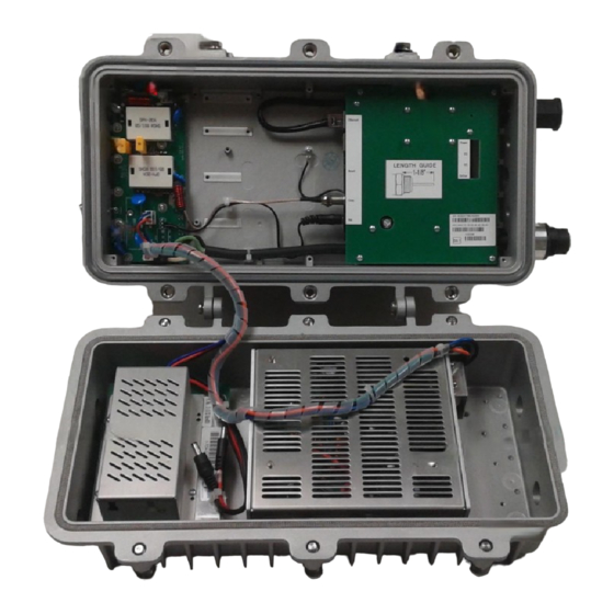
- Page 6 LBDG-250-DC-8200-1 • Plug-in SVP type surge protection. • Socket for optional solid state, crowbar type surge protection. • A power-interrupt to disconnect AC power. SECTION 2 COMPONENTS IDENTIFICACION SURGE CABEL WEATHER ARRESTOR INTERRUPT MODEM SEAL HFC INPUT UPSTREAM & ETHERNET...
-
Page 7: Section 3 Installation
3.1 Pre-Installation Upon receipt of the LBDG-250-DC-8200-1, inspect the carton for any external damage. If damage is present , inspect the Gateway exterior for damage. Report any apparent damage to the shipping agent and the Lindsay Broadband sales office. - Page 8 LBDG-250-DC-8200-1 3.2 Installation Diagrams Strand Mount Strand Mount with Hanger Brackets 3.3 Power Requirements The DOCSIS 3.1 Gateway can be connected to any power-passing coupler or splitter. The following formula can be used to calculate the current draw for your installation:...
- Page 9 LBDG-250-DC-8200-1 3.4 Output Receptacle Wiring...
- Page 10 -installation. 5. Connect the output DC power cable between the LBDG-250-DC-8200-1 and the device to be powered. 6. Re-install the AC interrupt. The indicator LED’s on the cable modem will indicate start-up, discovery and provisioning. (Refer to the cable modem installation guide for more information.)
- Page 11 11. Tape all connections to reduce moisture intake. 3.6 Ethernet Cable Installation The external RJ45 connector on the Lindsay LBDG-250-DC-8200-1 Gateway provides an IP68 weather-tight connection. A cable that is pre-terminated with an RJ45 connector can be used. No tools are required.
-
Page 12: Top View
LBDG-250-DC-8200-1 SECTION 4 LBDG-250-DC-8200-1 HOUSING 4.1 Housing Dimensions TOP VIEW 16.375” 9.750” RIGHT END SIDE VIEW 6.375” SIDE VIEW FROM HINGE 1.875” 1.250”... - Page 13 LBDG-250-DC-8200-1 4.2 Table of Specifications Lindsay LBDG-250-DC-8200-1 Gateway with DC Power Supply Specifications Cable Modem Band Plans DOCSIS 3.1 Network Configuration and Management TFTP, SNMP (V1, V2c, V3), Telnet, HTTP Input Impedance 75 Ω Privacy BPI+ Downstream Modulation Up to 32 SCQAM or 2 OFDM Modem F Port +15 to -15dBmV Housing 5/8"...
Need help?
Do you have a question about the LBDG-250-DC-8200-1 and is the answer not in the manual?
Questions and answers