Advertisement
Available languages
Available languages
Before you begin - Read these instructions completely and carefully.
IMPORTANT – OBSERVE ALL GOVERNING CODES AND ORDINANCES.
Note to Installer – Be sure to leave these instructions with the Consumer.
Note to Consumer – Keep these instructions with your Owner's Manual for future reference.
INTRODUCTION
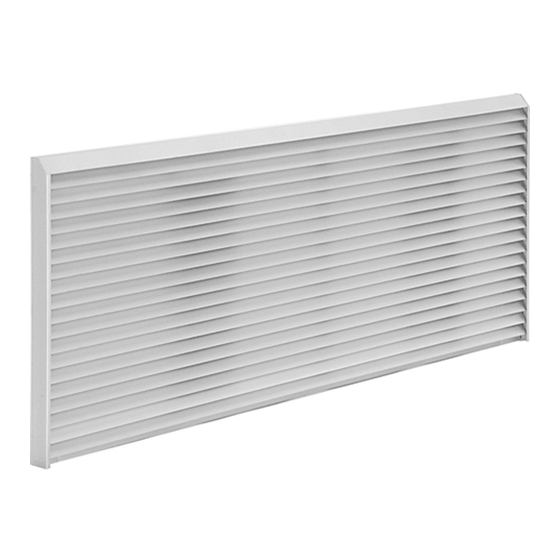
These instructions cover the installation of the Aluminum Architectural Rear Grille accessory for the packaged
terminal air conditioner and heat pump. The grille securely attaches to the rear of the wall sleeve with four pre-set
stainless steel screws. This grille is compatible with all RAB71*, RAB81*, and RAB78 series wall sleeves.
TOOLS NEEDED
• 1/4" Nutdriver • Pliers
CAUTION
Improper installation of accessory grille could result in condenser (outdoor) air recirculation. This
will degrade performance of the unit and possibly shorten product life. Manufacturer does not assume responsibility
for improper installation of grille resulting with condenser air recirculation.
IMPORTANT: Check For Proper Orientation
Before attempting to install grille, be sure to check it for proper orientation. The grille should be oriented with louvers
pitching downward.
STEP 1
panel from the roomside by bringing the panel through
the sleeve into the room. (To prevent dropping the panel,
push out the slit in the center of the outdoor panel to use
as a handhold.)
GE is a trademark of the General Electric Company. Manufactured under trademark license.
Installation Instructions
for your new
RAG42AA
Aluminum Architectural Rear
Grille
INSTALLATION
Screws
Screws
31-5000774 Rev. 0 02-24
Advertisement
Table of Contents

Related Manuals for GE RAG42AA


Summary of Contents for GE RAG42AA
- Page 1 (To prevent dropping the panel, push out the slit in the center of the outdoor panel to use as a handhold.) 31-5000774 Rev. 0 02-24 GE is a trademark of the General Electric Company. Manufactured under trademark license.
-
Page 2: Installation Instructions
Installation Instructions STEP 2: Aligning Grille with Wall Sleeve STEP 3: Mounting Grille to Wall Sleeve Back out the (4) mounting screws approx. 1/4” to 5/16”. Line up and insert grille mounting screws into keyhole Firmly grasp grille by holding the grille with one hand slots on the back of wall sleeve. - Page 3 Installation Instructions FOR USE WITH DRAIN KITS 90º Elbow Tube • Remove the knockout on the appropriate side using a pair of pliers. 31-5000774 Rev. 0 04-23 GEA...
- Page 4 Notes...
-
Page 5: Outils Requis
Instructions d’installation de votre nouvelle trousse de panneaux intérieur et extérieur RAG42AA Grille arrière en aluminium architectural Avant de commencer - Lisez ces instructions attentivement et en entier. IMPORTANT – OBSERVEZ TOUS LES CODES ET RÈGLEMENTS EN VIGUEUR. Note à l’installateur – Assurez-vous de laisser ces instructions au consommateur. -
Page 6: Instructions D'installation
Instructions d’installation murale murale Alignez et insérez les vis de montage de la grille dans les Dévisser les (4) vis de montage d’environ 1/4 à 5/16 po. fentes en trou de serrure situées à l’arrière de la gaine Saisissez fermement la grille en la tenant d’une main et murale. - Page 7 Instructions d’installation POUR UTILISATION AVEC DES TROUSSES DE VIDANGE • Retirez la débouchure du côté approprié à l’aide d’une pince. 31-5000774 Rev. 0 04-23 GEA...
- Page 8 Remarques...
-
Page 9: Instalación
Instrucciones de Instalación para su nuevo RAG42AA Rejilla Trasera Arquitectónica de Aluminio Antes de comenzar – lea estas instrucciones completamente y de forma detenida. IMPORTANTE – CUMPLA CON TODOS LOS CÓDIGOS Y ORDENANZAS GUBERNAMENTALES. Nota para el Instalador – Asegúrese de entregar estas instrucciones al Consumidor. -
Page 10: Instrucciones De Instalación
Instrucciones de instalación PASO 2: Alineación de la Rejilla con la Carcasa PASO 3: Montaje de la Rejilla en la Carcasa de de Pared Pared Alinee e inserte los tornillos de montaje de la rejilla en las ranuras preperforadas sobre la parte trasera de la carcasa con una mano y el asa con lazo con la otra mano. - Page 11 Instrucciones de instalación PARA USO CON KITS DE DRENAJE Tubería de Codo de 90º • Retire la tapa de plástico del lado apropiado usando una pinza. 31-5000774 Rev. 0 04-23 GEA...
- Page 12 Notas...
Need help?
Do you have a question about the RAG42AA and is the answer not in the manual?
Questions and answers