Table of Contents
Advertisement
Quick Links
ISTRUCTION FOR THE MAINTENANCE
OPERATOR OF THE UNIT V261
Thank you for purchasing this VI.BE.MAC. S.p.A. industrial sewing machine.
Before using this automatic unit, please read the following instructions in order to gain a better
understanding of how the machine operates. The instructions illustrate the correct working
method to follow in complete compliance with current legislation.
No part of this catalogue can be copied without asking VI.BE.MAC. S.p.A.
The information content in this catalogue can be changed at any time without advising by
VI.BE.MAC. S.p.A.
To request an other manual or to get technical advice regarding this unit feel free to contact:
VI.BE.MAC. S.p.A.
Società soggetta a direzione e coordinamento di Jack Europe S.à.r.l.
Via Monte Pastello 7/i, 37057 S.Giovanni LUPATOTO (VR)
Ph. (+39) 045 8778151 - Fax. (+39) 045 8779024
Email: customercare@vbm-grp.com- Website:
www.vibemac.com
Suggestions to improve this manual are appreciated.
REV. 2.1
22-06-2020
1
Advertisement
Table of Contents

Related Manuals for Vi.Be.Mac V261


Summary of Contents for Vi.Be.Mac V261
- Page 1 The instructions illustrate the correct working method to follow in complete compliance with current legislation. No part of this catalogue can be copied without asking VI.BE.MAC. S.p.A. The information content in this catalogue can be changed at any time without advising by VI.BE.MAC.
-
Page 2: Table Of Contents
Feller position ..............18 20.5- Resetting the panel values ............ 44 10.2- Adjustable lower side ............18 20.6- Paramater list ..............45 V261 MECHANICAL ADJUSTMENTS ......19 20.7- Error list ................47 11.1- Needle bar position ............. 19 21. PHOTOCELL ..............48 11.2- Needle bar stroke .............. - Page 3 SEIKO SEWING MACHINE CO LTD 11-3 IMADO I-CHOME VI.BE.MAC. S.p.A. provides a guarantee with respect to the contents of this publication, with express prohibition to use this publication itself for other purposes of any commercial, practical, TAITO KU, TOKIO 111...
-
Page 4: Introduction
VI.BE.MAC. S.p.A. MECHANISM MOOVING: VI.BE.MAC. S.p.A. disclaims any and all liability for a failure to observe the safety and prevention BEFORE DOING THE OPERATION BE SURE THAT THE MACHINE IS rules outlined in the various sections of this manual and for any damage caused by improper STOPPED AND DISCONNECTED FROM MAIN SWITCH use. -
Page 5: Conditions For Use
2. CONDITIONS FOR USE unit, carried out by unqualified personnel, will NOT be recognized as defective and will not be covered by the guarantee. These will be charged at the normal price, including All operations that comply with the following conditions are considered “normal”: consequent delivery and/or installation costs. -
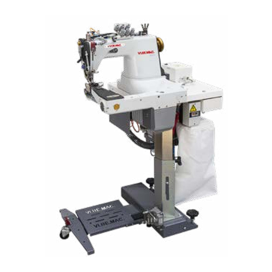
Page 6: General Machine Specifications
The VIBEMAC V261 is a 3 needles chain-stitch feed of the arm machine, made for top stitching and lap seaming in the manufacturing process of the denim trousers, chinos, work wear, denim 5.2- Lighting... -
Page 7: Description Of Switches And Commands
6. DESCRIPTION OF SWITCHES AND COMMANDS 6.3- Sense of rotation On the unit V261 there are the following switches: On VI.BE.MAC. V261 unit the sense n is automatically given by the of rotatio XL-CE 6.1- Main switch MITSUBISHI Servomotor It is positioned under the table fixed on the right side of the stand leg. -
Page 8: Threading Path
8.1- Needle thread path under the table. For the V261 unit to perform at 100 % and the stitch quality to be perfect it is very important that the thread is inserted correctly, please check below the correct thread path. To adjust the tension of the thread please rotate the thread disks knob. -
Page 9: Lubrication And Maintenance
9. LUBRICATION AND MAINTENANCE LAP SEAM FELLER Every day before starting production need to check the oil level in the marked areas. There are two types of Feller. Clean the machine at least once a day with an air gun to remove dust from the sewing The NORMAL type to perform the operations of seam and. -
Page 10: Feller Position
10.1- Feller position V261 MECHANICAL ADJUSTMENTS The V261 unit uses a new sewing head expressly realized for this type of seam by VI.BE.MAC. S.p.A. To aligned correctly the feller loosen the fixing screw and: The operator MUST always switch off the machine, following procedure. STOPPING THE MACHINE before accessing any sewing unit. -
Page 11: Needle Bar Stroke
To adjust the needle bar stroke loosen the screws highlited in red and moove the eccentric up The unit V261 uses needles type UY 128. For the correct mechanical regulation of the needle to make the needle bare stroke longer or down to make the needle bar stroke shorter. -
Page 12: Loopers Adjustments
T e c h n o l o g y COPYRIGHT 2009 Il presente disegno e' di esclusiva proprieta' della Ditta VI.BE.MAC. Non e' consentita la riproduzione e l'utilizzo a nessun titolo senza autorizzazione scritta dalla VI.BE.MAC. REV. 2.1 22-06-2020 REV. -
Page 13: Upper And Lower Meeting Point
12.5- Looper translation movement 12.4- Upper and lower meeting point The looper translation movement has to be adjusted that when the needle is going down has to The correct timing of the looper movement versus the needle has to be as in the images below, pass almost touching the looper and in the same way when the needle is going upwards. -
Page 14: Feed Dog And Fabric Feeding
Feed dog and fabric feeding The position of the eccentric for the height movement is when rotating the machine in the running direction and have the second shaft fixing grub screw just passed the service hole the 13.1- Feed dog position first screw for the eccentric to be aligned with his service hole. -
Page 15: Feed Dog Movement
Needle guard adjustments 13.2- Feed dog movement The feed dog movement is given by the two eccentrics highlighted as A for the forward-back The needle guard is positioned on the feed dog support and is moving in the same time with the movement and the height movement given by the eccentric highlighted as B, in the below feed dog, for that reason the needle guard position have to be checked every time the stitch image .1. -
Page 16: Feed Dog
FEED DOG 15.2- Feed dog movement The correct movement of the feed dog is when it moves performing a rectangular movement. 15.1- Feed dog height adjustment (up, forward, down, back) Feed dog must be adjusted so that when it is in the highest position the teeth are completely 31.1 out from the needle plate as image 30.1 The flat part between the teeth must be at the same level of the needle plate. -
Page 17: Stitch Length
15.4- Differential feed dog adjustment 15.3- Stitch length For the correct mechanical regulation of the differential feed dog is that it will move at the same As per image 32.1 below, loosen the screw (A) that fixes the eccentric. With the screw (B) it is speed of the main feed dog.To adjust the transport, loosen the screw A that fixes the eccentric possible to adjust the stitch lenght: and unscrew the B screw to increase the transport and tighten it to reduce the transport (as... -
Page 18: Thread Pullers Adjustment
Thread pullers adjustment PULLER ADJUSTMENT The thread pullers must be adjusted correctly, in order to have a good stitch quality and to The leaver 1 (image 35.1) is to increase or reduce the transport of the puller device. It is very avoid the stitch skipping. -
Page 19: Trimmer Device Regolation
To adjust the distance between the puller belt and the needle clamp screw or unscrew the end stroke bar. 261KRAS-C COD. COMPONENTE: VI.BE.MAC. 36.1 m e n T e c h n o l o g y GRUPPO RASAFILO CPL - MOD.C... - Page 20 the moving knife of the thread trimmer device is is moved by a rack cylinder , the movement The adjustment of the moving knife position is made by losing the screw (picture 39.1) and have to be adjusted like in the below pictures (38.1 and 38.2) and don’t have to touch the sides moving the rack cylinder back or forward.
-
Page 21: Sewing Cycle Parameters
SEWING CYCLE PARAMETERS 40.1 40.2 41.1 Sewing Start During normal sewing (without High pressure on presser foot (3 bar) thickness) Final funcion programmable S mode (↓+B+D) Presser foot low pressure (1.2 bar) After the photocell detects the end of the Parameter K32 (standard value 12) High speed (4999 rpm) fabric the machine sil start the suction... -
Page 22: Speed Percentage Setting
20.4- Test Input and Output 20.2- Speed percentage setting On the display appears: On the display appears: ☐ 2 - 9 9 ☐ 2 - 9 9 Press the DOWN arrow key and the UP arrow key and button A in the same time. ↑... -
Page 23: 2- Output Test
20.6- Paramater list 20.4.2- Output test Filename:V261 Sheetname:XCG Parameters 1Page 07/04/2020 Sewing machine model(Setting=280M Comparative=280M) While the machine is operating, it is possible to see the function and the signal changing from Function Mode Digital Function name Unit MIN MAX... -
Page 24: Error List
20.7- Error list Filename:V261 Sheetname:XCG Parameters 2Page 07/04/2020 Sewing machine model(Setting=280M Comparative=280M) 1008 LMH. Upper limit of medium speed [M] x100rpm 1009 LML. Lower limit of medium speed [M] x100rpm Error code Probable cause Inspection 1102 CWC. Rotation direction changeover prohibit 1103 12C. -
Page 25: Photocell
PHOTOCELL SENSOR ADJUSTMENT The presser foot compensating system is activated by a N/C sensor that has to be regulated in The photocell should be adjusted so that it points the underlying reflecting plate to adjust the this way: inclination, loosen the two screws that fix it to the bracket and move it slightly so that the green 22.1- Flat sewing light is on, when the fabric is positioned, both lights must be on. -
Page 26: Stop Position
STOP POSITION NEEDLE LOW This unit has 2 STOP positions: 1. STOP position is when the machine stops after releasing the pedal and the loopers have already entered the thread (as image 50.2) and in this position the detector is facing down (as image 50.1) 50.1 50.2... - Page 27 REV. 2.1 22-06-2020 REV. 2.1 22-06-2020...
-
Page 28: Pneumatic Diagram
PNEUMATIC DIAGRAM 24.1- Topographic Pneumatic Diagram Ø8 ROSSO TRASPARENTE REV. 2.1 22-06-2020 REV. 2.1 22-06-2020... -
Page 29: Problem Solving
• Check if the upper head thread holder is positioned parallel to the sewing head (see image DISTRIBUTOR FOR: VI.BE.MAC. S.p.A. Società soggetta a direzione e coordinamento di Jack Europe S.à.r.l. Via Monte Pastello 7/i, 37057 S.Giovanni LUPATOTO (VR) Ph.
Need help?
Do you have a question about the V261 and is the answer not in the manual?
Questions and answers