Table of Contents
Advertisement
Quick Links
INSTRUCTION FOR THE MAINTENANCE
OPERATOR OF THE UNIT V300
INTRODUCTION
Thank you for purchasing this VI.BE.MAC. S.p.A. industrial sewing machine.
Before using this unit, please read the following instructions in order to gain a better understanding of
how the machine operates. The instructions illustrate the correct working method to follow in complete
compliance with current legislation.
No part of this catalogue can be copied without asking VI.BE.MAC. S.p.A.
The information content in this catalogue can be changed at any time without advising by VI.BE.MAC. S.p.A.
To request an other manual or to get technical advice regarding this unit feel free to contact:
VI.BE.MAC. S.p.A.
Via Monte Pastello 7/i
37057 S.Giovanni Lupatoto (VR)
Ph. (+39) 045 8778151
Fax. (+39) 045 8779024
Email:
customercare@vbm-grp.com
www.vibemac.com
"Suggestions to improve this manual are appreciated"
1
REV. 1.3 07/2018
Advertisement
Table of Contents

Related Manuals for Vi.Be.Mac V30


Summary of Contents for Vi.Be.Mac V30
- Page 1 No part of this catalogue can be copied without asking VI.BE.MAC. S.p.A. The information content in this catalogue can be changed at any time without advising by VI.BE.MAC. S.p.A. To request an other manual or to get technical advice regarding this unit feel free to contact: VI.BE.MAC.
-
Page 2: Table Of Contents
Index INTRODUCTION ..................6 1.1- Manual conservation ....................6 GENERAL FEATURES OF THE MACHINE ............ 7 2.1- Power supply ......................7 2.2- Compressed air supply and consumption ..............7 2.3- Dimension and weight ....................7 2.4- Working position .....................7 CONDITIONS FOR USE ................8 3.1- Guarante conditions ....................8 LIFTING AND TRANSPORT ............... 9 INSTALLATION .................. - Page 3 15.16- Folder regulation ....................44 15.17- Folder sensor regulation ..................44 15.18- Photocell centring ....................45 15.19- Skip stitch photocell regulation ................45 15.20- Photocell centring di STOP ..................46 15.21- Regulation needle bar translation ................47 15.22- Regulation needle bar translation end stroke ............47 15.23- Motor regulation ....................48 15.24- Puller regulation .....................49 ELECTRICAL DIAGRAM ................50 PNEUMATIC DIAGRAM ................67 17.1- Technical Pneumatic Diagram ................67 17.2- Topografic Pneumatic Diagram ................68...
- Page 4 Declaration of CE Conformity Translated Version VI.BE.MAC. S.p.A. The company: Via Monte Pastello 7/i 37057 San Giovanni Lupatoto VERONA - ITALIA Tel. +39-045-8778151 Fax +39-045-8779024 In quality of manufacturer, declares under its responsability that the product: COMPANY: VIBEMAC MODEL: V300...
- Page 5 SAFETY SIGNALS ELECTRICAL SHOCK DANGER: BEFORE OPENING THE COVER OR DOING THE OPERATION SWITCH OFF THE MAIN POWER MECHANISM MOOVING: BEFORE DOING THE OPERATION BE SURE THAT THE MACHINE IS STOPPED AND DISCONNECTED FROM MAIN SWITCH DANGER: BE SURE TO FOLLOW THE ISTRUCTION DANGER: THE TEMPERATURE WILL BE OVER 70C°-160F°...
-
Page 6: Introduction
Do not remove or deteriorate labels, texts, and warnings on machine parts. If you need to restore them, contact VI.BE.MAC. S.p.A. VI.BE.MAC. S.p.A. Disclaims any and all liability for non-compliance with the safety and prevention rules described in the various sections of this manual and for any damage caused by improper use. -
Page 7: General Features Of The Machine
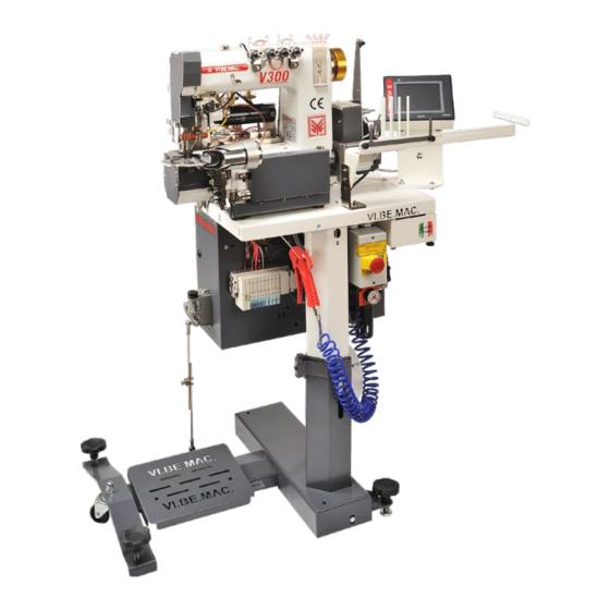
GENERAL FEATURES OF THE MACHINE The V300 waistband unit is equipped with an automatic cutting device, plier to perform a straight cut and a programmable skip stitch system to attach waistbands on jeans trousers, casual trousers, classics and work clothes…The automatic unit is composed by the following principal groups: ∙VIBEMAC Sewing machine. -
Page 8: Conditions For Use
CONDITIONS FOR USE All operations that comply with the following conditions are considered “normal”: ∙the user applies all instructions in this manual and CE directives ∙all safety standards are respected, not removing the casing or safety catches installed by the manufac- turer ∙the power supply is constant and does not fluctuate by more than 10% ∙the unit has to be connected under an automatic cut-out switch of 30mA... -
Page 9: Lifting And Transport
LIFTING AND TRANSPORT Make sure that during lifting the whole Position the machine on the truck surly fixed with machine rests on the forklift forks. straps or balts that will insure the stability during the transport. Make sure that during unloading the whole machine Remove straps, and loosen the fixing screws, rests on the forklift forks. -
Page 10: Installation
INSTALLATION WARNING: THE INSTALLATION MUST BE PERFORMED ONLY BY SPECIALIZED PERSONS We disclaim all responsibility for damages resulting from installation not complying with these instructions or from connecting the machine to power and utility lines not satisfying the necessary requirements. The machine should not be installed in environments in which explosive materials or substances are present. -
Page 11: Description Of Buttons And Controls
DESCRIPTION OF BUTTONS AND CONTROLS 6.1- Machine Main Switch The main switch is located below the table on the central leg of the stand. There are two buttons: The RED (OFF) button on the left for turning the unit off. The BLACK (ON) button on the right for turning the unit on. -
Page 12: Machine Start-Up
MACHINE START-UP Press the black “ON” button on the main switch. The machine will perform a complete rotation 360° and re position in the same position that the needle was when switched on To make the unit position with needles in up position back pedal once. The sewing head is ready to operate in AUTOMATIC mode with the last program used. - Page 13 CLEAN CHECK OIL SEWING LEVEL AT EVERY ORGANS AT SHIFT EVERY SHIFT OIL SAE 100 REV. 1.3 07/2018...
-
Page 14: Threading The Unit
THREADING THE UNIT REV. 1.3 07/2018... -
Page 15: Command Pedal
COMMAND PEDAL It is positioned at the base of the stand, connected by a connecting rod to the lever of the Motor panel. The pedal has 4 positions: 1. Forward, to increase the sewing speed; 2. Neutral; 3. Back pedal, to rise the presser foot; 4. -
Page 16: Touch Screen Functions
TOUCH SCREEN FUNCTIONS From the working screen it is possible to select the most common features that the operator will use during the production. 1. Puller up/down function , by pressing the key the puller will move from up to down and viceversa 2. -
Page 17: Start Parameters
14.1- Start parameters From the working screen press the START icon to adjust the start cutting and skip stitch This screen will appear: Activate or deactivate the initial skip stitch Set skip stitch lenght Activate or deactivate the initial cutting Set initial cutting lenght To select electronic or pneumatic skip stitch Return to home page... -
Page 18: End Parameters
14.2- End parameters From the working screen press the END icon to adjust the final cutting and skip stitch This screen will appear: Activate or deactivate the final skip stitch Set skip stitch lenght (stitches) Activate or deactivate the final cutting Set initial cutting lenght Enables/disables electronic or pneumatic skip stitch Return to home page... -
Page 19: Menu
14.3- Menu From the working screen press the MENU icon to enter the following regulations: To access the sewing parameters To access the input test To access the output test To access the bobbin counter parameters Language selection Return to home page To change the value of the parameter 1-2-3 (Sewing parameter, Test input, Test output) is necessary to insert 2536 the password... -
Page 20: 1- Sewing Parameters
14.3.1- Sewing parameters Once entered the sewing parameter menu on the display will appear the options as lower image: Pressing the RIGHT arrow icon (A) will change page to next page of parameters REV. 1.3 07/2018... - Page 21 1. Stitch lenght Pressing the key a numerical key board will appear input the desired value and confirm pressing enter. After changing stitch length always regulate the needle bar transport. 2. Inch or millimetre selection To change from mm to inches, simply press the 2 key and the selection will automatically change REV.
- Page 22 3. Photocell folder position Standard final Long final Very long final skip stitch skip stitch skip stitch 52 mm 80 mm 99 mm REV. 1.3 07/2018...
- Page 23 4. Folder photocell filter Applying folder photocell filter , is to be used only in special cases , this will apply a filter to the photocell adding the same number of points inserted to the skip stitch programmed. tis filter must be used only in special cases to avoid thatt the unit will execute the skip stitch and cut in the middle of the sewing cycle caused by the caracteristics of the fabric.
- Page 24 5. Intermediate stop A) intermediate stop disabled (OFF) IN CASE THERE IS SOME EXTRA FABRIC WAISTBAND With the intermediate stop position DISABLED the unit will perform the complete trousers cycle with skip stitch and cutting in the beginning and at the end. B) intermediate stop enable (ON) IN CASE THERE IS NO EXTRA FABRIC WAISTBAND...
- Page 25 6. Automatic cycle In automatic cycle the unit will work with skip stitch and cutting. In “Only manual sewing” only the sewing head will be working 7. Speed adjustment From the following screen you can adjust the speed of each transaction, and the following screen where you can select whether you are using the rotary hook or looper.
- Page 26 Adjusting the needle position In Adjusting the needle position, is possible to regulate, Up stop position, Down stop position and Bobbin change position Each regulation will have a min. and max. value . PRESS HOME PAGE TO RETURN TO THE WORKING SCREEN. REV.
- Page 27 9. Timer list From timer list it is possible to change the timer value To return to the working screen press Home page. 10. Cut offset Cut offset is to balance the start and end cut in case there may be some difference, if set the start and end cut at the same value you must have a result equal (as image ) 20mm 20mm...
- Page 28 If the result setting the same value is that the cut is longer in the START (as image) you can correct it by increasing the value towards END CUTTING If the result setting the same value is that the cut is longer in the end (as image) you can correct it by increasing the value towards START CUTTING.
- Page 29 11. Factory setting Pressing Factory setting this screen will appear, if confirmed pressing yes all parameters will returned to standard VI.BE.MAC. values. If pressing Cancel or X on the upper right side the machine will return to the previous screen.
-
Page 30: 2- Test Input
14.3.2- Test Input In “Test Input” you can control the operation of each input. To test the sensors just pass a metellic object in front of it, while to test the photocells just pass under a piece of fabric. The status will change from “ON” to “OFF”. PEDAL SIGNAL: Pressing the pedal or back pedaling the value will change. -
Page 31: 3- Test Output
14.3.3- Test Output In the test output is possible to check each output of the unit end verify if it is properly working. Pressing on the logical status (off in the image), on the side of each electro valve name and function it is possible to change it (to on) and check il the output is correctly working. -
Page 32: 4- Bobbin Counter
14.3.4- Bobbin Counter You can enable or reset this counter by pressing the button to turn on the meter, as an image. The writing will chance to colour and the writing will change to Left/Right bobbin counter enable Once Enabled the desired bobbin counter pressing Set will appear a numerical key board, insert the desired value and press Enter to confirm The value must be considered as multiplied... -
Page 33: 5- Language Selection
14.3.5- Language selection To select the language just keep pressed the flag and it will automatically change flag, once reached the desired flag (language) release the icon. To return to the working screen press Home page key. REV. 1.3 07/2018... -
Page 34: Mechanical Regulations
MECHANICAL REGULATIONS During all mechanical regulations switch off the unit from the main switch (image1) and remove the air from the main air slide valve (image 2) and always pay attention to the safety signals to avoid any kind of injuries to people or mechanical breakage 15.1- Needle change To change needle, always switch of the unit and loosen grab screw A remove the needle re position the needle... -
Page 35: Needle Bar Height
15.2- Needle bar height Needle bar hight must be adjusted so that from the needle point to the needle plate the distance must be 10,5mm. This measure is with 10,5mm needles 62x57 To adjust the needle bar hight open the front cover and loosen the screw, then loosening the internal grub screw and the needle bar will be lose, adjust it so that at upper dead point the distance from the needle and the needle plate is 10,5 mm this measure is with 62x57 needles. -
Page 36: Needle Bar Translation Adjustment
15.3- Needle bar translation adjustment The distance between the needle bar and the presser foot bar must be of 13,2 mm with needle bar in lower dead position. 13.2 mm To adjust this distance loosen the screw A position the needle bar at 13,2 mm from the presser foot bar and re tighten the screw. -
Page 37: Needle Bar Translation
15.5- Needle bar translation Always adjust the needle bar movement on the basis of the selected stitch length. To do so press button stitch length button (image A) on the upper part of the head and turn the hand wheel. When button A is pressed down: - Turning the hand wheel towards the operator (anticlockwise) will increase the translation - Turning the hand wheel towards the operator (clockwise) will decrease the translation. -
Page 38: Meeting Point Regolation
15.7- Meeting point regolation From the cam that has two screws (image2) it’s possible to regulate the moovement of the looper that must be in syncrony with the needle Loosen the screws and position the first so it wil be reachable from the service hole (image 1) and position the needle bar in lower dead point .Rotate the cam so that the point of the looperin forward and backward stroke will pass in the middle of the needle (image 3-4 ) The cam must be positioned with the second screw in sense of rotation (anti clock wize) in corrispondance... -
Page 39: Regolation Looper
15.8- Regolation looper Position the needle bar in lower dead point , loosen the two screws (image A) that fix the looper support to the shaft and check that the distance between the looper point and the needle must be 4,5mm(image 1). Once set fix the screws. -
Page 40: Regulation Of Spreader
15.9- Regulation of spreader From the cam (image A) is possible to sincronize the moovement of the spreader with the looper. Position the needle bar , using the hand wheel so that the needle hole and the looper hole are aligned (image B) With the needle bar in this position the cam screws must be (as image) one un and one facing the operator. -
Page 41: Spreader Movement
15.11- Spreader movement The movement of the pin that makes the spreader move must be the same forward and backwards respect to the axis of the shaft (image 1-2) and can be adjusted from the grab screw that fixes it to the shaft , on the lower part .to acheive the maximum race of the spreader the cam must be positioned at &mm from the shaft (image3). -
Page 42: Spreader Play Regulation
15.12- Spreader play regulation If the spreader has some play left or right, it’s possible to adjust it: Loosen the 2 grab screws (image A). Tighten the ring so that the movement of the eccentric is free and there is the least play possible. 15.13- Spreader pin position The end of the pins should be bent slightly to the right (2 mm) in order to prevent the thread from slipping. -
Page 43: Needle Plate
15.14- Needle Plate To help the opening of the triangle, on the lower side, the needle plate on the under right side is a little slanted (see lower image). This operation is usually made by hand with sand paper to increase the opening of the triangle little more 15.15- Needle plate thread cutting blade regulation The thread cutting blade under the needle plat must be regulated so that the blade will overcome the eyelet for 2 mm. -
Page 44: Folder Regulation
15.16- Folder regulation You must first select the “AUTO” display, this will activate the “MANUAL” function. Loosen the screw A to adjust the trimmer forward, backward, left and right. Loosen screw B to adjust the trimmer in the top and bottom. Once the folder is centred correctly, adjust screws C so that the folder surface will be nice and firm. -
Page 45: Photocell Centring
15.18- Photocell centring Appy the spacer with LOCTITE 243 and verify that the hole is perfectly in the center of the red light of the photocell and that the milling is positioned towards the needlesso the hole will remain clean. SPACER 15.19- Skip stitch photocell regulation Press the front button (picture 1) once, place a single layer of fabric over the spacer, stretch it and press the... -
Page 46: Photocell Centring Di Stop
15.20- Photocell centring di STOP The photocell must be adjusted so that it will read on the side of the plate (image 1). Press the front button (image 2) once and position one layer of fabric nice and flat under the photocell and press again the button. If the operation is done succesfully on the display must appear 0 with a maximum tolerance of ±... -
Page 47: Regulation Needle Bar Translation
15.21- Regulation needle bar translation The needle bar translation nust be adjusted by the eccentric . The purpose of the eccentric is to sincronize the movements on the needles with the fabric . To adjust correctly the eccentric : ∙slightly tighten the grab screw (image1) and leave the other one loose ∙press the button to regulate the stitch lenght (image 2) ∙rotate the hand wheel antyi clock wize till end stroke ∙loosen the grab screw that previously was slightly tighten (image 1) -
Page 48: Motor Regulation
15.23- Motor regulation 1. Fix the first screw of the coupling in rotation sense, in the motor shaft grove (image 1). 2. Tighten the second one, leaving the screws of the sewing machine shaft loose. 3. Turn on the unit, at this point the motor will do a complete rotation. 4. -
Page 49: Puller Regulation
15.24- Puller regulation The puller device can be regulated to the right or left to obtain more or less curve on the waist band and rotated in case of a very curved waist band. To adjust the puller right or left loosen the 2 screws (image 1) and move the puller to the desired position and tight again the screws. -
Page 50: Electrical Diagram
ELECTRICAL DIAGRAM REV. 1.3 07/2018... - Page 51 REV. 1.3 07/2018...
- Page 52 REV. 1.3 07/2018...
- Page 53 REV. 1.3 07/2018...
- Page 54 REV. 1.3 07/2018...
- Page 55 REV. 1.3 07/2018...
- Page 56 REV. 1.3 07/2018...
- Page 57 REV. 1.3 07/2018...
- Page 58 REV. 1.3 07/2018...
- Page 59 REV. 1.3 07/2018...
- Page 60 REV. 1.3 07/2018...
- Page 61 REV. 1.3 07/2018...
- Page 62 REV. 1.3 07/2018...
- Page 63 REV. 1.3 07/2018...
- Page 64 REV. 1.3 07/2018...
- Page 65 REV. 1.3 07/2018...
- Page 66 REV. 1.3 07/2018...
-
Page 67: Pneumatic Diagram
PNEUMATIC DIAGRAM 17.1- Technical Pneumatic Diagram REV. 1.3 07/2018... -
Page 68: Topografic Pneumatic Diagram
17.2- Topografic Pneumatic Diagram REV. 1.3 07/2018... - Page 69 DISTRIBUTES: Via Monte Pastello 7/i 37057 S. GIOVANNI LUPATOTO (VERONA), ITALIA Tel. (+39) 045 8778151 - Fax (+39) 045 8779024 Web Site: www.vibemac.com Email: customecare@vbm-group.com...
Need help?
Do you have a question about the V30 and is the answer not in the manual?
Questions and answers