Table of Contents
Advertisement
INSTRUCTIONS FOR "VIBEMAC 3022WB406" AUTOMATIC UNIT WITH
LS01PMG DIGITAL PANEL
INTRODUCTION
Thank you for buying this industrial sewing machine of VI.BE.MAC. S.p.A.
Before starting to operate with this automatic unit, please read carefully the following instructions so as to help you to
understand the working of the machine.
These will explain you the working system that must be followed according to the current regulations.
•
Any part of this manual can be copied or transcribed without forwarding the application to VI.BE.MAC. S.p.A.
•
The content of this handbook can be subject to alterations without notice.
To ask for a new manual or have explanations on every information or technical note presented in this volume, please
contact:
In case of followings improvements, some incongruities on technical notes might appear in this manual. Therefore, we
suggest You always to contact our Tech. Dept. to check if new version of this manual or new deepening are available.
"Suggestions on possible mistakes and signalling to improve this handbook will always be welcomed"
1
3022CS AUTOMATIC UNIT
VI.BE.MAC. S.p.A.
TECHNICAL DEPARTMENT
Via Monte Pastello 7/ I
37057 S. GIOVANNI LUPATOTO
(VERONA) - ITALIA
Phone +39 045 8778151
Fax +39 045 8779024
E-mail:
vibemac@vibemac.com
Web site:
http://www.vibemac.com
Morandin Dario
3022 406 001 A Version
Advertisement
Table of Contents

Related Manuals for Vi.Be.Mac 3022 Series


Summary of Contents for Vi.Be.Mac 3022 Series
- Page 1 These will explain you the working system that must be followed according to the current regulations. • Any part of this manual can be copied or transcribed without forwarding the application to VI.BE.MAC. S.p.A. • The content of this handbook can be subject to alterations without notice.
-
Page 2: Table Of Contents
3022CS AUTOMATIC UNIT INDEX page 1. GENERAL FEATURES OF THE MACHINE .......................... 4 1.1.SUPPLY TENSION ................................4 1.2.CONSUMPTION AND PRESSURE OF THE COMPRESSED AIR.................. 4 1.3.DIMENSIONS AND WEIGHT............................4 1.4.WORKING PLACE ................................4 2. TERMS OF USE ..................................5 2.1.WARRANTY FORM ................................. 5 3.1 GENERAL SWITCH OF THE MACHINE ......................... - Page 3 3022CS AUTOMATIC UNIT 10.1.PHOTOCELLS ................................34 10.2. SAFETY SENSOR ..............................34 10.3. PHOTOCELLS SETTINGS ............................35 11. ELECTRO VALVES ................................36 11.1.CUTTING ..................................36 11.2.UNSTITCHING................................36 11.3.PINCER..................................36 11.4.SAFETY ..................................36 11.5.PRESSER FOOT LIFTER............................36 11.6.NEEDLE COOLING ..............................36 12. SAFETY MICRO SWITCH ..............................36 13.
-
Page 4: General Features Of The Machine
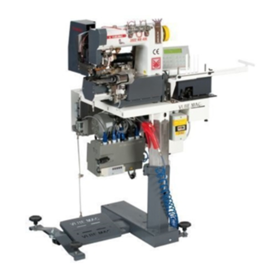
3022CS AUTOMATIC UNIT 1. GENERAL FEATURES OF THE MACHINE The VIBEMAC 3022 machine is equipped whit an AUTOMATIC device to cut and unstitch at the required measure, the two ends of a waistband fabricated by a border unit. The Material Cutting, the Pneumatic 1 needle Unstitching and the Stitching Cycle Automatic Stopping functions are executed by the LS01 PMG Digital Logic panel, while the Electronic Unstitch and the sewing speed control functions are executed by the MITSUBISHI XL-CE servomotor with the new kind GMFY panel. -
Page 5: Terms Of Use
All the parts damaged for negligence by the user and/or for an incorrect setting of the machine by technical staff not allowed by VI.BE.MAC to carry out the maintenance, will NOT be considered defectives by the manufacturer. Those parts will be charged including all the eventual carriages and/or installation expenses. -
Page 6: General Switch Of The Machine
3022CS AUTOMATIC UNIT 3. DESCRIPTION OF SWITCHES, BUTTONS AND CONTROLS In the 3022CS unit are the following switches: 3.1 GENERAL SWITCH OF THE MACHINE It is placed under the table fixed to the pillar of the support. There are two switches: The RED one on the left side (OFF) is used to take off current to the unit. -
Page 7: Working Cycle
3022CS AUTOMATIC UNIT 7. WORKING CYCLE In the 3022 unit the different counters on the LS01PMG panel have two different measure unities: impulses to obtain a tolerance of only + ¼ stitch on the cutting counter, while in msec for the unstitching. For example the value of 5 stitches in a cutting counter corresponds to the value of 20 impulses, that is the value of stitches that you want to insert always multiplies by four. -
Page 8: Begining Of The Trousers Program 4
3022CS AUTOMATIC UNIT 7.3. BEGINING OF THE TROUSERS PROGRAM 4 The operator inserts the material under the photocell N°1, the insertion of trousers automatically allows the lifting of the presser foot. The counter step 9 – 2 (initial unstitching preparation) activates and the conveyor pulls the waistband according to the quantity selected. -
Page 9: Ls01/Pmg"Logic Panel
8.1. .DESCRIPTION OF THE FRONTAL KEYBOARD 0 – 9 Numerical keyboard to set the values VI.BE.MAC. 3022 Shift the slide towards right of a step 1, PROGRAM 3 Shift the slide towards left of a step Shift the slide to the preceding line... -
Page 10: Ignition Of The Machine
Press the key to activate the panel and set the AUTOMATIC working of the machine. The display changes as follows: VI.BE.MAC. 3022 1, PROGRAM 3 Press the key OFF to deactivate the panel and set the NORMAL working of the machine. -
Page 11: How To Create A Sequence Of Programs
Press ENTER to exit 8.3.2. HOW TO CREATE A SEQUENCE OF PROGRAMS At the ignition of the machine on the display appears: VI.BE.MAC. 3022 1, PROGRAM 3 Press the key SEL, on the display appears: selection program 3, 0, 0, 0, Insert the number of the first ( 1°) program, insert the number of the second (2°), insert the number of the third ( 3°),... -
Page 12: How To Set The Cut And Unstitching Counter In The Program N°3
3022CS AUTOMATIC UNIT Press the key RESET, the panel goes back to the first program in the sequence if used. 8.3.5 HOW TO SET THE CUT AND UNSTITCHING COUNTER IN THE PROGRAM N°3 Inside the program in execution are used two different types of counter, A and B. Every counter can be used many times in a sequence, with a maximum value of 250 stitches/setting. -
Page 13: 3.Setting Of The Count Starting Position Of The Final Unstitching (Program 3)
3022CS AUTOMATIC UNIT Switch the motor off and wait until the display switches off too, then switch the unit on again step 13 – 2 8.3.5.3.SETTING OF THE COUNT STARTING POSITION OF THE FINAL UNSTITCHING (PROGRAM 3) Press the key PROG, on the display appears: A COUNTER Set with the numeric keyboard, the number of the required counter, in this case press 2 Press the key ENTER... -
Page 14: Setting Of The Initial Cutting Count (Program 3)
3022CS AUTOMATIC UNIT 8.3.5.5 SETTING OF THE INITIAL CUTTING COUNT (PROGRAM 3) Press the key PROG, on the display appears: A COUNTER Press the arrow up to change to counter B on the display appears: B COUNTER Set with the numeric keyboard, the number of the required counter, in this case press 1 Press the key ENTER B COUNTER 1 N POINTS =... -
Page 15: How To Set The Cut And Unstitching Counter In The Program N°4
3022CS AUTOMATIC UNIT 8.3.6. HOW TO SET THE CUT AND UNSTITCHING COUNTER IN THE PROGRAM N°4 Inside the program in execution are used two different types of counter, A and B. Every counter can be used many times in a sequence, with a maximum value of 250 stitches/setting. Their purpose is to keep or delay the insertion of a function. -
Page 16: 3.Setting Of The Start Position Final Unstitching Count (Program 4)
3022CS AUTOMATIC UNIT Switch the motor off and wait until the display switches off too, then switch the unit on again 8.3.6.3.SETTING OF THE START POSITION FINAL UNSTITCHING COUNT (PROGRAM 4) Press the key PROG, on the display appears: A COUNTER Set with the numeric keyboard, the number of the required counter, in this case press 2 Press the key ENTER A COUNTER 2... -
Page 17: 6.Setting Of The Final Cutting Count (Program 4)
3022CS AUTOMATIC UNIT 8.3.6.6.SETTING OF THE FINAL CUTTING COUNT (PROGRAM 4) Press the key PROG, on the display appears: A COUNTER Press the arrow up to change to counter B on the display appears: B COUNTER Set with the numeric keyboard, the number of the required counter, in this case 1 Press the key ENTER B COUNTER 1 N POINTS =... -
Page 18: Direct Programming Of The Number Of Impulses Per Stitch
3022CS AUTOMATIC UNIT Insert the required value for the input n°.2 when changes from OFF to ON (up Front). Usually is set the value 8 Confirm with the key ENT The display changes as follows: Final cut On Phot 2 = xx Off Phot 3 = xx Insert the required value for the input n°.3 when changes from ON to OFF (down Front). -
Page 19: Inputs Control From Photocell Or Detector
Confirm with the key ENT 8.6. TEST FUNCTION At the ignition of the machine on the display appears: VI.BE.MAC. 3022 1, PROGRAM 3 Press the key TEST and keep it pressed until the second acoustic signal The display changes as follows:... -
Page 20: Inputs Control From The Motor Panel
3022CS AUTOMATIC UNIT 8.6.2. INPUTS CONTROL FROM THE MOTOR PANEL Through the arrow down, place the flashing cursor beside the Test Positions Test. The display changes as follows: test inputs LS01 test position Confirm with the key ENT The display changes as follows: inputs from motor MITSUBISHI GMFY 0 0 0... -
Page 21: Control Of The Automatic Speed Outputs And Motor Stop
To exit the function and return to the principal Menu press the key ENT 8.6.5.EXIT THE TEST FUNCTION With the arrow down, place the flashing cursor beside the Test end. The display changes as follows: test Speed test End Confirm with the key ENT On the display appears: VI.BE.MAC. 3022 1, PROGRAM 3... -
Page 22: Set The Duration Of The Cutting Impulse
3022CS AUTOMATIC UNIT 8.7.SET THE DURATION OF THE CUTTING IMPULSE At the ignition of the machine on the display appears: VI.BE.MAC. 3022 1, PROGRAM 3 Press the key PROG keep it pressed until the second acoustic signal The display changes as follows:... -
Page 23: Mitsubishi Servomotor
3022CS AUTOMATIC UNIT 9. MITSUBISHI SERVOMOTOR On the automatic unit is installed a MITSUBISHI servomotor of the XL-554 CE series combined to a panel of the GMFY series and a un Positioner of the XC-KE-01P series. The Panel has a specific programming of the Inputs/Outputs, altered respect a to that mass produced. On the motor is assembled a pulley of 85mm diameter of and the machine rotates at about 4000 stitch per minute. -
Page 24: Setting Of The Maximum Sewing Speed-Positioning-Cutting
3022CS AUTOMATIC UNIT 9.2.3.SETTING OF THE MAXIMUM SEWING SPEED-POSITIONING-CUTTING On t he display of the control panel appears: Press the arrow up and down at the same time On the display appears the writing: Keep the two keys pressed until the writing changes as follows: H = Maximum Set Speed Adjust on value 4199 for the Chain Stitch Machine Adjust on value 3199 for the Lockstitch machine... -
Page 25: Setting Of The Output Implulse Number To Command A Step By Step Motor
3022CS AUTOMATIC UNIT 9.2.4.SETTING OF THE OUTPUT IMPLULSE NUMBER TO COMMAND A STEP BY STEP MOTOR This adjustment is necessary to change the rotatory speed of the Step by Step motor on the grounds of the required stitch length. On the display of the control panel appears: Press the arrow down and the key C at the same time Keep the two keys pressed until the writing changes as follows:... -
Page 26: Inputs/Otputs Test
3022CS AUTOMATIC UNIT 9.2.5.INPUTS/OTPUTS TEST On the display of the control panel appears: Press the arrow up and down and the key A at the same time On the display appears the writing: Keep the two keys pressed until the writing changes a s follows: On the display is visualized the last error message shown by the machine Press the arrow down On the display appears... - Page 27 3022CS AUTOMATIC UNIT On the display appears: Real hours of the motor rotation: the value must be multiplied by 10 (Total hours = n° X 10) Press the arrow down View of all the available INPUTS (from iA to i5) with the possibility of manual check On the display appears: The INPUT value (ON/OFF) of the parameter i A is visualized.
- Page 28 3022CS AUTOMATIC UNIT Input parameter of the MOTOR ENCODER phase B Revolving the synchronizer on the machine is possible to change it from o n to o f or vice versa. Press the arrow down On the display appears: Input parameter of the High Thread puller detector position Revolving the synchronizer on the machine is possible to change it from o n to o f or vice versa.
- Page 29 3022CS AUTOMATIC UNIT View of all the signals that go from CPU to the INPUTS while the sewing machine is working On the display appears: SOFTWARE CHECK- In case of bad working of the outputs check the PARAMETERS placed in the MITSUBISHI motor The value of the OUPUT signal of the parameter 0 A d is visualized.
- Page 30 3022CS AUTOMATIC UNIT Press the arrow down On the display appears: Press the arrow down On the display appears: Press the arrow down On the display appears: Press the arrow up and the arrow down at the same time to exit...
-
Page 31: Write The Programming Into The Memory Panel (Backup)
3022CS AUTOMATIC UNIT 9.2.6.WRITE THE PROGRAMMING INTO THE MEMORY PANEL (BACKUP) Switch the machine on keeping pressed the arrow down the button A and C at the same time Switch on On the display appears the writing: P - q (q mode) Keep the THREE buttons pressed until the writing changes in: U C S. -
Page 32: List Of Errors
3022CS AUTOMATIC UNIT Press the button D to make the copying cycle start.. Keep it pressed until the writings flashes three time On the display of the control panel appears: 2 – 9 9 9.2.8. LIST OF ERRORS E - x If during the working one of the following messages appears switch the machine on and check the cause of the problem through the following steps. -
Page 33: List Of Parameters
3022CS AUTOMATIC UNIT 9.2.9.LIST OF PARAMETERS First thing set : 280M (Factory setting) Mode Function Parameter Standard Set and Type C Mode Input Input Input Medium Speed Initial Cut Input Ingresso (value parameter speed 2 ) Stopping cycle Function Slow Speed Cut Input (value parameter speed 1 ) Medium Speed Final Cut Input (value parameter speed 3 ) -
Page 34: Inputs
3022CS AUTOMATIC UNIT 10. INPUTS 10.1.PHOTOCELLS The THREE (3) photocells on the machine are of the "RT01" type. Their function is to signal to the logic LS01 panel the position of the trousers on the machine worktable. The photocells read the position of the trousers through the stainless steel mirror fixed to the worktable. This kind of photocells has two (2) light to check the working: GREEN LIGHT ON ·... -
Page 35: Photocells Settings
3022CS AUTOMATIC UNIT 10.3. PHOTOCELLS SETTINGS On these photocells the position, the inclination and the sensibility can be varied. THE POSITION Loosen the fixing screw A and shift the photocell along the fixing rod. N°3 N°2 N°1 A from internal side THE INCLINATION Loosen the fixing screw A and rotate the photocell along the axis. -
Page 36: Electro Valves
3022CS AUTOMATIC UNIT 11. ELECTRO VALVES The Electro Valves assembled in the machine are the following: 11.1.CUTTING This 5 way EV6 Electro Valve, of the EA58ML model, has a 6W 24V DC bobbin. This commands the cutting cylinder fixed to the shearing machine and it is connected to the LS01 panel through the 9 poles rear OUTS connector. -
Page 37: Cylinders
3022CS AUTOMATIC UNIT 13. CYLINDERS In the machine there are 5 cylinders for the following functions: 13.1.CUTTING Is a 40/40 cylinder with internal bumper. Is connected through the fork to the superior mobile knife, and it is fixed in the back to a vertical support, through a pin blocked by a grub screw. -
Page 38: Pulling Material Device
3022CS AUTOMATIC UNIT 14. PULLING MATERIAL DEVICE The pulling material device, continuously, uses a couple of cylinders placed behind the Presser Foot and before the Cutting device. While the speed of the lower roller is given by the Step by Step motor, the upper roller receives the movement through a pulley with a variable diameter. -
Page 39: Lower Toothed Roller
3022CS AUTOMATIC UNIT 14.2.LOWER TOOTHED ROLLER The purpose of the lower toothed roller moved by the step by step motor, is to shift the material on the grounds of the required length stitch and to pull the lower part of the waistband, so that the material is perfectly joined and sewed by the Unit, to increase the wereability of the waistband of the trousers, even though in the presence of peculiar materials like stretch, multifibres etc. -
Page 40: Band Guide
3022CS AUTOMATIC UNIT 16. BAND GUIDE The purpose of the band guide is to guide and slightly pull the waistband before its entrance in the Border. Set the adjustable support as to obtain the right tension. In case of STRETCH material decrease to minimum the number of passages, to avoid problems with the measure of the sewn waistband, after his application on the trousers. -
Page 41: Adjustment Of The Mechanical Equipment
3022CS AUTOMATIC UNIT 18. ADJUSTMENT OF THE MECHANICAL EQUIPMENT The user MUST turn the unit off following procedure 5. HOW TO STOP THE MACHINE before performing any adjustment. 18.1 CUTTING DEVICE The user MUST turn the unit off following procedure 5. HOW TO STOP THE MACHINE. Here is a list of the most common adjustments that must be carried out on the machine in case of bad working. -
Page 42: Lower Knife Chage
3022CS AUTOMATIC UNIT 18.1.4 LOWER KNIFE CHAGE Remove the movable knife group, loosening the fixing bolt with a 10 mm key and unscrewing the pressure adjustment screw. Loosening the three (3)fixing screws, with a 4 mm Allen key. Remove the knife and clean carefully the support. Insert the new knife e reassemble the whole. -
Page 43: Mechanical Adjustment Of The Sewing Head
Here is a list of the most common adjustments that must be carried out on the machine in case of bad working. We remind you that only that only the staff authorized by VI.BE.MAC. Spa is qualified to repair the machine in object. -
Page 44: Needle Plate
3022CS AUTOMATIC UNIT 19.2.NEEDLE PLATE For the correct adjustment of the sewing head, check that the different mechanical parts are adjusted according to the following scheme: Lightly round off the hole of the needle in the lower right angle. Needle Plate section Place the needle place towards so that the needle is lightly out of center respect to its own hole, as represented in the picture below: Needle... -
Page 45: Eccentric For The Translation Movement Of The Needle Bar
3022CS AUTOMATIC UNIT 19.4.ECCENTRIC FOR THE TRANSLATION MOVEMENT OF THE NEEDLE BAR The purpose of this eccentric is to move the needle in synchrony with the material. 19.4.1.POSITION Place the Needle Bar to the Lower Dead Center, in order to find the correct position of the eccentric of the Needle Bar translation, respect to the Upper shaft inside the sewing head, so that the movement is perfectly symmetric respect to the needle plate hole. -
Page 46: Needle Bar Pendulum Position
3022CS AUTOMATIC UNIT 19.5. NEEDLE BAR PENDULUM POSITION The adjustment of the position of the needles respect to the hole of the Needle Plate is very important, if it is not correctly executed this might lead to troubles during the stitching (skip of the stitch). Rotate the wheel with the hand, with the movement of the needle toward down, when the hole on the needle and is at the same level of the plate loosen the fixing screw (1) of the pendulum of the Needle Bar. -
Page 47: Eccentric Of The Loop Startings Movement
3022CS AUTOMATIC UNIT 19.6.ECCENTRIC OF THE LOOP STARTINGS MOVEMENT The purpose of this eccentric is to move in synchrony with the needle movement the looper movement, starting of the Needle Bar descent movement with starting of the stroke backward the loop and vice versa. 19.6.1.POSITION In order to place correctly the eccentric of the looper movement starting respect to the needle place the Needle Bar to the Lower Dead Center. - Page 48 3022CS AUTOMATIC UNIT In this way, the point of the looper passes through the needle respect to the position of the dimple: • In the forward movement of the looper it is lower respect to the center line of the dimple itself •...
-
Page 49: Distance Between Looper- Needle
3022CS AUTOMATIC UNIT 19.7. DISTANCE BETWEEN LOOPER- NEEDLE To place correctly the loop group respect to the needle, place the Needle Bar to the Lower Dead Center. Loosen the two screws (A) (six-sided head) that fix the clamp to the shaft and check that the distance between the center of the needle and the point of the looper is of 5mm. -
Page 50: Spreader Phase
3022CS AUTOMATIC UNIT 19.8.SPREADER PHASE The purpose of this eccentric is to move the comb of the spreader in synchrony with the movement of the needle and with the movement of the looper. 19.8.1.POSITION To place correctly the eccentric of the starting of the spreader movement place the Needle Bar to the following Phase point. -
Page 51: Length Of Movement
3022CS AUTOMATIC UNIT 19.8.2.LENGTH OF MOVEMENT Its purpose is to adjust the movement of the Spreader translation as wider as possible. The position of the eccentric respect to the transversal shaft determines the lever arm and so the total shifting of the Spreader. Always place the fixing screws of the eccentric as shown in the picture below and then shift the eccentric towards right or left. -
Page 52: Position Of The Spreader Movement Pin
3022CS AUTOMATIC UNIT 19.8.3.POSITION OF THE SPREADER MOVEMENT PIN When the Spreader is completely shifted to left, the distance between the support shaft (A) and the 2 brackets to its extremities is of 5mm on the right side and of 15mm on the left side. Loosen the two fixing screws (B) of the support (C) to perform the correct adjustment. -
Page 53: Stitch Length
19.9.STITCH LENGTH The 3022 automatic unit uses a new sewing head expressly built for this kind of sewing from VI.BE.MAC. Spa. To vary the stitch length modify the number of impulses per revolution for the Step by step Motor following the specific directions in the paragraph about the motor panel. -
Page 54: Cleaning
3022CS AUTOMATIC UNIT 20. CLEANING The user MUST turn the unit off following procedure 5. HOW TO STOP THE MACHINE. Clean every day with an air compressed jet the following places: · the machine in general, especially under the needle plate. ·... -
Page 55: Electrical Connection
3022CS AUTOMATIC UNIT 22. ELECTRICAL CONNECTION 22.1. LS01 PANEL In the rear side of the LS01/P panel, there are three cup connectors. Their function is the following: • CON1, cup shaped, connects the motor panel to the LS01/P logic panel. •... - Page 56 3022CS AUTOMATIC UNIT 22.2. MITSUBISHI MOTOR Connector Connector Connector Connector Option B F.L. S.M. option A SEWING MACHINE Ground Ground +24V/+30V +24V Photocell Number 1 Stopper Material (optional) +24V/+30V +24V 0V/(+5V) +24V/+30V +24V Needle Cooler OPTION A opening head added Switch +12V/(+5V) +12V Rotation conveyor signal...
-
Page 57: Card Of The Gac03 And Ofm30 Step By Step Motor Running
3022CS AUTOMATIC UNIT 22.3.CARD OF THE GAC03 AND OFM30 STEP BY STEP MOTOR RUNNING Connector Connector Connector Connector Option B F.L. S.M. Option A White Brown Female Grounding Male Tip N°1 BLACK N°2 BLUE N°3 YELLOW Feeding N°4 BROWN Transformer 60V 50Hz Female connector N°1 BLACK... -
Page 58: Pneumatic Standard Scheme
3022CS AUTOMATIC UNIT 23. PNEUMATIC STANDARD SCHEME Needle Blow Unstitching Cutting Air Cock Pulle Pincer Presser Foot Safety Electro valve Usually open – soft spring... -
Page 59: Pneumatic Scheme For Presser Foot And Puller Lift At The Same Time
3022CS AUTOMATIC UNIT 24. PNEUMATIC SCHEME FOR PRESSER FOOT AND PULLER LIFT AT THE SAME TIME Needle Blow Unstitching Air Cock Cutting Pulle Pincer Presser Foot safety Electro valve Usually open – soft spring... - Page 60 3022CS AUTOMATIC UNIT...
- Page 61 3022CS AUTOMATIC UNIT...
Need help?
Do you have a question about the 3022 Series and is the answer not in the manual?
Questions and answers