
Subscribe to Our Youtube Channel
Related Manuals for PIAB AVM 2


Summary of Contents for PIAB AVM 2
- Page 1 Manual Manual AVM™2 AVM™2 Automatic Vacuum Management Automatic Vacuum Management P3010 AVM™2 P3010 AVM™2 P5010 AVM™2 P5010 AVM™2 P6010 AVM™2 P6010 AVM™2 Art no 0117735 Rev.08, EN, 2021-10 Original instructions...
- Page 2 This manual is available in the following languages at piab.com Chinese English French German Italian Japanese Korean Polish Portuguese Russian Spanish Swedish...
-
Page 3: Table Of Contents
Contents 1. Introduction to the manual ..4 6. Service and repair ....21 About the manual ....4 6.1 Spare parts . -
Page 4: Introduction To The Manual
Wear eye protection manuals for the respective ejectors The manual is available for download at piab.com in the 12 languages shown on page 2. The original instructions are written in English. Wear ear protection •... -
Page 5: Safety Instructions
Safety instructions 2. Safety instructions The product described in this manual is designed for Warning! implementation in industrial systems; therefore, it must not be used with conditions other than those • Ensure no foreign matters enter the specified herein. exhaust port due to the risk of ejected objects and damage of the product. -
Page 6: Introduction To Avm
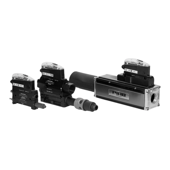
SE-18212 DANDERYD SWEDEN 3.1.1 Identification label Each unit is identified by a label with identification information. For any communication with Piab AB or service centers always refer to the label information. 3.2 Product overview AVM™2 (Automatic Vacuum Management) is a control unit for vacuum ejectors. -
Page 7: Technical Data
Introduction to AVMTM2 3.3 Technical data General Electric Characteristics Supply voltage 22–28 VDC (typical 24 VDC) Maximum ripple , 50-60 Hz Power consumption Nom. 2.6W @ 28 VDC (max. 7.5W) Maximum load on the outputs 40 mA (short-circuit protected) MTBF (electronics) 40,000 hours according to MIL-HDBK-217E Reversed polarity protection 5 minutes at 23°C [73.4°F]... -
Page 8: Dimensions
Safety instructions 3.4 Dimensions 3.4.1 P3010 1 COAX cartridge. ® Figure 2 P3010 dimensions with 1 COAX ® 2 COAX cartridges. ® Figure 3 P3010 dimensions with 2 COAX ® Page 8/24 Manual... - Page 9 Safety instructions 3.4.2 Dimensions P5010 P5010 Figure 4 P5010. 1. Compressed air, 2. Vacuum, 3. Exhaust 3.4.3 Dimensions P6010 P6010 4x M5 G1" 6.69" 0.866" 8.42" 4.61" G1/4" M12 8-pin G1/4", 1/4"NPSF G1/4" G1", 1" NPSF 10.5 G1/8", 1/8"NPSF 0.413" G1", 1"NPSF 18.5 0.728"...
-
Page 10: Compliance
Safety instructions 3.5 Compliance 3.6 Intended use • For professional use only. • The product shall be used to evacuate air (non- liquids) from a volume to create vacuum for European Directives, CE gripping, holding and processes. Directive Standard and/or •... -
Page 11: Installation
Installation 4. Installation 4.2.1 P3010 AVM™2 AVM™2 can be installed in any orientation. Ensure that the exhaust (3) from the ejector is not blocked. When connecting supply air (1) and vacuum hoses (2) to the unit, it is important to choose proper pipe dimensions to prevent pressure drops. - Page 12 Installation 4.2.2 P5010 AVM™2 ™ Figure 7 P5010 AVM Note Position Description Ø3/8”, Ø10mm Compressed air G3/4”, G1/2”, 3/4” Vacuum NPSF, 1/2” NPSF Ø16mm Exhaust Loosen the screws 3/4” (option 1/2”) For more detailed information see the dimensional drawing. Page 12/24 Manual...
-
Page 13: Electrical Connection
Installation 4.2.3 P6010 AVM™2 Figure 8 A: standard version, B: with separated blow-off Position Description Note Compressed air G1/4”, Ø10mm Vacuum G1”, G3/4”, 1” NPSF, 3/4” NPSF Exhaust G1/4”, Ø10mm Separate blow-off (compressed air) G1/4”, Ø10mm For more detailed information see the dimensional drawing. 4.3 Electrical connection 4.3.1 pin configuration Figure 9 M12-8 pin connector. - Page 14 Installation 4.3.2 PNP type Figure 10 Schematics PNP. PNP type Note Name Description Wiring color cable 0110238 Supply 24VDC (V+) White Common (V-) Brown Control signal, on/off Green Option: automatic Control signal, blow-off Yellow blow-off, 1 sec Output signal sensor S1 Grey Output signal sensor S2 Pink...
-
Page 15: Cable Assemblies
Installation 4.3.3 NPN type Figure 11 Schematics NPN. NPN type Description Note Wiring color cable 0110238 Name Supply 24VDC (V+) White Common (V-) Brown Control signal, on/off Green Control signal, blow-off Option: automatic Yellow blow-off, 1 sec Output signal sensor S1 Grey Output signal sensor S2 Pink... -
Page 16: Operation
Operation 5. Operation 5.2 Pneumatic diagram Warning! Do not use the product if the exhaust is restricted or blocked. 5.1 Internal/external electrical functionality yellow green green Figure 14 1: compressed air, 2: vacuum, 3: exhaust. Position Description COAX® Multi-stage ejector. Vacuum valve, NO or NC/NC 2 (NO shown. -
Page 17: With Energy-Saving Function Activated
Operation • LEDs that show the status of valves and vacuum Vacuum signals. Level S1 • LED display that shows the current vacuum level Level S2 in -kPa or -inHg in the normal position. Output S2 on • On AVM™2 units for P6010, there is an option to Output S1 on blow from a separate port to maximize blow-off efficiency in the vacuum system. -
Page 18: Setting The Vacuum-Signal Level
Operation 5.6 Setting the vacuum-signal level The default setting for the AVM™2 is -kPa. In order to switch to showing the vacuum signal levels in With AVM™2 it is easy to set a suitable vacuum- -inHg, you should press the ES button and keep it signal level for the system. -
Page 19: Service And Repair
Service and repair 6. Service and repair The AVM unit do not require any regular service. If needed the poppet valves can be replaced. Warning! • Prior to any maintenance work, suspend pneumatic/electrical supply, and discharge residual pressure. • Irresponsible use of supply air may cause injury. - Page 20 Service and repair Description Art no Control unit AVM™2 NO 0117923 Control unit AVM™2 NC (power off - NO) 0117922 Control unit AVM™2 NC 2 (power off - NC) 0126714 Control unit AVM™2 NO, automatic blow-off (1 sec) 0126570 Control unit AVM™2 NC, automatic blow-off (1 sec) 0126571 Function P3010 AVM™2 NO 0117921...
-
Page 21: P3010 Avm™2 Exploded View
Service and repair 6.1.1 Repair kit 6.2 P3010 AVM™2 exploded view Suitable for all models ™ Figure 22 P3010 AVM 2 parts. Description 2x M3x8 mm TX Figure 21 Repair kit. M5x10 A. Repair kit 9.1x1.6 mm Art. No. 0124255 Black poppet valve cpl (incl. -
Page 22: P5010 Avm™2 Exploded View
Service and repair 6.3 P5010 AVM™2 exploded view 6.4 P6010 AVM™2 exploded view. ™ Figure 23 P5010 AVM 2 parts. Description 2x M3x8 mm TX M5x10 Figure 24 P6010 AVM™2 parts. 9.1x1.6 mm Description 2x 4.76x1.78 mm 2x M3x8 mm TX 1.4x1 mm M5x10 34.2x3 mm... -
Page 23: Warranty
Seller or its authorized representatives, or have a Piab is certified against with ISO-14001, and also defect as a result of fair wear and tear or willful complies with REACH (EC 1907/2006). - Page 24 +33 (0)16-430 82 67 +46 (0)8-630 25 00 +55 (0)11-449 290 50 +86 21 5237 6545 +33 (0)16-430 82 67 +46 (0)8-630 25 00 +55 (0)11-449 290 50 +86 21 5237 6545 info-france@piab.com info-sweden@piab.com info-brasil@piab.com info-china@piab.com info-france@piab.com info-sweden@piab.com info-brasil@piab.com info-china@piab.com Mölndal...
Need help?
Do you have a question about the AVM 2 and is the answer not in the manual?
Questions and answers