Table of Contents
Advertisement
Quick Links
Advertisement
Table of Contents

Related Manuals for jcb 3.50QE


Summary of Contents for jcb 3.50QE
- Page 1 Quick Start Guide JCB POWER PACK 3.50QE – 3.75QE – 3.100QE...
-
Page 2: Table Of Contents
INDEX Disclaimer Dimensions & Volumes Key Components General Checks Start Up Instructions Victron Control Panel Overview Victron Control Panel Initial Setup Deep Sea Control Panel Overview Deep Sea Control Panel Initial Setup Lifting Positioning Emergency Stops Please consult your manual for full information or consult your local dealer... -
Page 3: Disclaimer
This machine should not be operated by any person who isn’t appropriately qualified or had the appropriate training. Operation of this machine without periodic maintenance could cause it to malfunction. For more information please contact your JCB Dealer. Please consult your manual for full information or consult your local dealer... -
Page 4: Dimensions & Volumes
DIMENSIONS & VOLUMES MODEL 3.50QE 3.75QE 3.100QE OUTPUT – V TOTAL STORAGE CAPACITY - kWh MAXIMUM DEPTH OF DISCHARGE - % CAPACITY TO 90% DEPTH OF DISCHARGE - kWh RECOMMENDED MAX OUTPUT - kW LENGTH 2175 2175 2175 WIDTH 1307... -
Page 5: Key Components
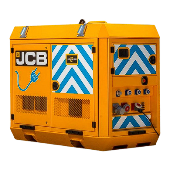
KEY COMPONENTS - EXTERNAL Lifting Point Strap Guides Fork pockets Ventilation grilles Control Panel Emergency Stop Front View Power Connections Isometric view for clarity Side View Please consult your manual for full information or consult your local dealer... - Page 6 KEY COMPONENTS - CONTROLS Control Screen (2 styles) ON / OFF Buttons MCCB Emergency Stop Control panel and cable connection doors removed for clarity Please consult your manual for full information or consult your local dealer...
- Page 7 KEY COMPONENTS - CONTROLS Single phase 16A Input Three phase 125A input Single Phase Output (either 3 x 32A or 3 x 16A) Three phase 125A Output Three Phase Output (either 63A or 32A) Genset autostart terminals Solar inputs Input busbar Output busbar Control panel and cable connection doors removed for clarity...
-
Page 8: General Checks
GENERAL CHECKS Before Use After correct installation of the unit, the power pack must be fully checked over before first starting can be attempted. Points to check include: • A visual inspection for signs of damage. • Ensure all ventilation grilles are unobstructed (300mm free air recommendation). -
Page 9: Start Up Instructions
START UP INSTRUCTIONS 1. Open door (A) to access the power pack 2. Ensure DC isolator (B) is in the ON position Please consult your manual for full information or consult your local dealer... - Page 10 START UP INSTRUCTIONS 3. Ensure MCB (E) are in the ON position. 4. Press and hold the Green START button (B) for 10-20 seconds until the green ‘system available’ lamp illuminates. 5. Control panel (A) will start its initialisation (c20 seconds). 6.
-
Page 11: Victron Control Panel Overview
VICTRON CONTROL OVERVIEW AC Output AC Input NOTE: if you are not presented with this screen after startup then please swipe left or right to cycle to this screen. Input Supply Output Supply Inverter Status Battery Status (detail below) Inverting Passthru No AC input, AC connected to load. -
Page 12: Victron Control Panel Initial Setup
VICTRON INITIAL SETUP Settings Outp Inpu Outp Inpu Quattro 48/10000/140-2x100 Inverting Setting the Input current limit By touching the front screen the Pages and Menu options “pop up” Press the Menu Press Quattro Adjust the input current limit by pressing it to match the supply that will be connected to the machine 0-100A NOTE This parameter is to insure the unit will only draw the requested amount of... - Page 13 Setting up Distributed Voltage and Current Control - DVCC By touching the front screen the Pages and Menu options “pop up” Press the Menu Press Settings Press DVCC Adjust the Maximum charge current from 0A - 600A NOTE Changing the DVCC will change the amount of current that is used to charge the batteries.
-
Page 14: Deep Sea Control Panel Overview
DSE CONTROL OVERVIEW Generator Input Supply Mains Input Supply Solar Input Supply (optional) Battery Status Inverter Status Output Supply Please consult your manual for full information or consult your local dealer... - Page 15 DSE CONTROL OVERVIEW Alerts User Profile Socket Timer Setup Device List Settings Home Scroll Right Scroll Left Navigate/Push to Activate Please consult your manual for full information or consult your local dealer...
-
Page 16: Deep Sea Control Panel Initial Setup
DEEP SEA INITIAL SETUP Enabling Installer privileges On the screen press User button Press the scroll wheel to change the user Scroll to Installer Enter PIN using the scroll wheel (Default 1000) Press the Home button Notice the top of the screen changes to Installer NOTE Once initial setup is complete the system should be reset to Operator mode Please consult your manual for full information or consult your local dealer... - Page 17 Setting Maximum Input Limit On the Home screen press the Setting button Move to the second page Use the scroll wheel to scroll through the settings. Using the pencil buttons the settings can be changed Adjust the Gen Size kVA setting to match the size of Generator connected Adjust the Max Gen load % setting (0-100%) NOTE This parameter is to insure the unit will only draw the requested amount of...
- Page 18 Setting Maximum Charge Limit On the Home screen press the Setting button Move to the second page Use the scroll wheel to scroll through the settings. Using the pencil buttons the settings can be changed Adjust the Max Charge % setting (0-100%) NOTE Changing the Max Charge % will change the amount of current that is used to charge the batteries.
-
Page 19: Lifting
LIFTING The power pack should only be lifted using the designated lifting points or the fork pockets where provided. For movement on site the fork pockets enable the power pack to be lifted and shifted by forklift or telescopic handler. The fork pockets are sized and spaced to allow lifting by equipment with a standard fork carriage. -
Page 20: Positioning
POSITIONING Your JCB power pack has a rugged design and is suited for life on a hard working site, however there are precautions that should be undertaken to ensure a long service life • Units should be located on flat level ground •... -
Page 21: Emergency Stops
EMERGENCY STOP An emergency stop button is mounted externally on the canopy. If pressed, all machine systems will stop completely. Use the emergency stop button in the case of an emergency. Under normal operation the power pack should be turned off using the STOP button. This can be clarified in the Control Panel section of your Operators Manual. - Page 22 J C B Sales Limited, Rocester, Staffordshire, United Kingdom ST14 5JP Tel: +4 4 1889 590312 Email: salesinfo@jcb.com Download the very latest information on this product range at: www.jcb.com The J C B logo is a registered trademark of J C Bamford Excavators Ltd. ©2009 J C B Sales.
Need help?
Do you have a question about the 3.50QE and is the answer not in the manual?
Questions and answers