
Related Manuals for Asus AAEON UP Squared Pro 710H Edge


Summary of Contents for Asus AAEON UP Squared Pro 710H Edge
- Page 1 UP Squared Pro 710H Edge Maker Board System UPN-EDGE-ASLH01 User’s Manual 1st Ed Last Updated: April 29, 2024...
- Page 2 Copyright Notice This document is copyrighted, 2024. All rights are reserved. The original manufacturer reserves the right to make improvements to the products described in this manual at any time without notice. No part of this manual may be reproduced, copied, translated, or transmitted in any form or by any means without the prior written permission of the original manufacturer.
- Page 3 Acknowledgement All other products’ name or trademarks are properties of their respective owners. Microsoft®, Windows®, Windows® 10 IoT Enterprise are registered trademarks ⚫ of Microsoft Corp. Intel® is a registered trademark of Intel Corporation ⚫ Core™ is a trademark of Intel Corporation ⚫...
- Page 4 Packing List Before setting up your product, please make sure the following items have been shipped: Item Quantity UPN-EDGE-ASLH01 (UP Squared Pro 710H Edge) ⚫ DC in Phoenix Connector ⚫ If any of these items are missing or damaged, please contact your distributor or sales representative immediately.
- Page 5 About this Document This User’s Manual contains all the essential information, such as detailed descriptions and explanations on the product’s hardware and software features (if any), its specifications, dimensions, jumper/connector settings/definitions, and driver installation instructions (if any), to facilitate users in setting up their product. Users may refer to the product page at AAEON.com for the latest version of this document.
- Page 6 Safety Precautions Please read the following safety instructions carefully. It is advised that you keep this manual for future references All cautions and warnings on the device should be noted. Make sure the power source matches the power rating of the device. Position the power cord so that people cannot step on it.
- Page 7 If any of the following situations arises, please the contact our service personnel: Damaged power cord or plug Liquid intrusion to the device iii. Exposure to moisture Device is not working as expected or in a manner as described in this manual The device is dropped or damaged Any obvious signs of damage displayed on the device...
- Page 8 FCC Statement This device complies with Part 15 FCC Rules. Operation is subject to the following two conditions: (1) this device may not cause harmful interference, and (2) this device must accept any interference received including interference that may cause undesired operation.
- Page 9 China RoHS Requirements (CN) 产品中有毒有害物质或元素名称及含量 AAEON System QO4-381 Rev.A0 有毒有害物质或元素 部件名称 铅 汞 镉 六价铬 多溴联苯 多溴二苯醚 (Pb) (Hg) (Cd) (Cr(VI)) (PBB) (PBDE) 印刷电路板 × ○ ○ ○ ○ ○ 及其电子组件 外部信号 × ○ ○ ○ ○ ○ 连接器及线材 ○ ○...
- Page 10 China RoHS Requirement (EN) Hazardous and Toxic Materials List AAEON System QO4-381 Rev.A0 Hazardous or Toxic Materials or Elements Component Name PCB and Components Wires & Connectors for Ext.Connections Chassis CPU & RAM HDD Drive LCD Module Optical Drive Touch Control Module Battery This form is prepared in compliance with the provisions of SJ/T 11364.
-
Page 11: Table Of Contents
Table of Contents Chapter 1 - Product Specifications..................1 Specifications ......................2 Chapter 2 – Hardware Information ..................4 Dimensions ....................... 5 Jumpers and Connectors ..................7 2.2.1 List of Physical I/O Ports ................10 List of Jumpers and Connectors ................10 2.3.1 Power Button (SW1) .................. -
Page 12: Chapter 1 - Product Specifications
Chapter 1 Chapter 1 - Product Specifications... -
Page 13: Specifications
Specifications System Intel® Core™ i3-N305 (8C, 1.80 GHz, 15W) Intel® Processor N97 (4C, 2.00 GHz, 12W) Onboard Hailo-8™ Edge AI Processor Memory Up to 16GB Onboard LPDDR5 Graphics Intel® UHD Graphics for 12th Gen Intel® Processors Storage Up to 128GB onboard eMMC Ethernet 2.5GbE x 2 (Intel®... - Page 14 Power Supply Power Requirement 12V ~ 36V DC-in Phoenix Connector (Optional: Lockable Plug) Power Supply Type AT/ATX (Default: AT) Power Consumption 50W ~ 55W Mechanical Mounting VESA Mount/Wall Mount/DIN Rail (Optional) Dimensions (W x H x D) 5.28” x 4.13” x 2.36” (134mm x 105mm x 60mm) Net Weight 1.8 lb.
-
Page 15: Chapter 2 - Hardware Information
Chapter 2 – Hardware Information Chapter 2... -
Page 16: Dimensions
Dimensions Chapter 2 – Hardware Information... - Page 17 Chapter 2 – Hardware Information...
-
Page 18: Jumpers And Connectors
Jumpers and Connectors Component Side Chapter 2 – Hardware Information... - Page 19 Solder Side Chapter 2 – Hardware Information...
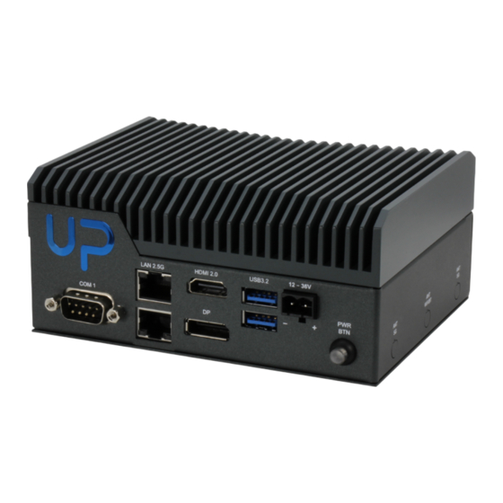
- Page 20 Front I/O Rear I/O Chapter 2 – Hardware Information...
-
Page 21: List Of Physical I/O Ports
2.2.1 List of Physical I/O Ports Label Function COM 1 Dual 2.5GbE LAN Port HDMI 2.0b Display Port 1.2 USB 3.2 Gen 2 (Type-A) Dual Port 12 ~ 36V DC-in Power Button GPIO COM 2 List of Jumpers and Connectors Please refer to the table below for all of the board’s jumpers and connectors that you can configure for your application Label... -
Page 22: Power Button (Sw1)
2.3.1 Power Button (SW1) Signal Signal Power Button 2.3.2 RTC (CN1) Signal Signal RTC_VCC Chapter 2 – Hardware Information... -
Page 23: M-Key Slot (Cn2)
2.3.3 M.2 M-Key Slot (CN2) Signal Signal Signal +3.3V +3.3V +3.3V +3.3V +3.3V +3.3V/2.5A PCIE3_RX- PCIE3_RX+ PCIE3_TX- PCIE3_TX+ Platform Reset PCIE_CLK3_D- PCIE_WAKE# PCIE_CLK3_D+ Key-M Key-M Key-M Key-M Key-M Chapter 2 – Hardware Information... -
Page 24: E-Key Slot (Cn4)
Signal Signal Signal Key-M Key-M Key-M +3.3V +3.3V +3.3V Note: M.2 M-Key Max 2.5A. 2.3.4 M.2 E-Key Slot (CN4) Signal Signal Signal +3.3V USB2_D+ +3.3V USB2_D- CNV_WR_LANE1_ CNV_WR_LANE1_ CNV_RF_RESET CNV_MODEM_CL CNV_WR_LANE0_ KREQ CNV_WR_LANE0_ CNV_WR_CLK_D- CNV_BRI_RSP CNV_WR_CLK_D+ Key-E Key-E Key-E Key-E Key-E Key-E Key-E... -
Page 25: Dual Lan (Cn6)
Signal Signal Signal PCIE10_TX- PCIE10_RX+ PCIE10_RX- PCIE_CLK2_D+ PCIE_CLK2_D- Suspend clock Platform reset BT_Enable PCIE_WAKE# Wi-Fi_Enable CNV_WT_LANE1_ CNV_WT_LANE1_ CNV_WT_LANE0_ CNV_WT_LANE0_ CNV_WT_CLK_D- +3.3V/2A CNV_WT_CLK_D+ +3.3V/2A Note: M.2 E-Key Max 1.5A. 2.3.5 Dual LAN (CN6) Signal Signal Signal LAN1_MDI0+ LAN2_MDI0+ LAN1_ACTLED- LAN1_MDI0- LAN2_MDI0- LAN1_ACTLED+ LAN1_MDI1+ LAN2_MDI1+... -
Page 26: Hdmi/Dp (Cn8)
Signal Signal Signal LAN1_MDI1- LAN2_MDI1- LAN1_LINK1000# LAN1_MDI2+ LAN2_MDI2+ LAN2_ACTLED- LAN1_MDI2- LAN2_MDI2- LAN2_ACTLED+ LAN1_MDI3+ LAN2_MDI3+ LAN2_LINK100# LAN1_MDI3- LAN2_MDI3- LAN2_LINK1000# R10A R10B 2.3.6 HDMI/DP (CN8) Signal Signal Signal DP_TX0+ DP_TX0- DP_TX1+ DP_TX1- DP_TX2+ DP_TX2- DP_CLK+ DP_CLK- CONFIG1 CONFIG2 DP_AUX+ DP_AUX- DP_HPD +3.3V/1A HDMI_TX2+ HDMI_TX2- HDMI_TX1+... -
Page 27: Dc Input (Cn12)
Signal Signal Signal HDMI_CLK- HDMI_SCL HDMI_SDA +5V/1A HDMI_HPD 2.3.7 DC Input (CN12) Signal Signal DC_IN 2.3.8 Dual USB 3.2 Gen 2 (Type-A) Port (CN13) Signal Signal Signal +5V/0.9A USB2_D1- USB2_D1+ USB3_RX1- USB3_RX1+ USB3_TX1- USB3_TX1+ +5V/0.9A USB2_D2- USB2_D2+ Chapter 2 – Hardware Information... -
Page 28: Com Port Wafer (Cn15)
Signal Signal Signal USB3_RX2- USB3_RX2+ USB3_TX2- USB3_TX2+ 2.3.9 COM Port Wafer (CN15) Signal Signal 2.3.10 COM Port Wafer (CN16) Signal Signal Chapter 2 – Hardware Information... -
Page 29: Pin Hat (Cn17)
Signal Signal 2.3.11 40 Pin HAT (CN17) Signal Signal +3.3V/2A +5V/2A I2C1_SDA +5V/2A I2C1_SCL GPIO3_ADC UART_TX UART_RX I2S_CLK GPIO4 GPIO5 GPIO19 +3.3V/2A GPIO20 SPI_MOSI SPI_MISO GPIO21 SPI_CLK SPI_CS0 GPIO23 I2C0_SDA I2C0_SCL GPIO11 GPIO12 PWM0 PWM1 I2S_FRM GPIO15 I2S_RX I2S_TX Chapter 2 – Hardware Information... -
Page 30: Front Panel (Cn21)
Note: Total 2A(5V) and 2A(3.3V) for 40 pin HAT. 2.3.12 Front Panel (CN21) Signal Signal RESET button Power button 2.3.13 AT/ATX Mode Selection (JP1) Signal ATX_MODE AT_MODE (default) Chapter 2 – Hardware Information... -
Page 31: Chapter 3 - Software Installation
Chapter 3 Chapter 3 – Software Installation... -
Page 32: Linux Setup
Linux Setup The UP Squared Pro 710H Edge supports Linux operating systems (see Chapter 1 for specifications). For instructions on how to install a Linux OS onto your UP Squared Pro 710H Edge, you can find several guides and tutorials in the wiki section of the UP website at https://up-board.org for both installing supported distributions as well as... -
Page 33: Hailo Driver Information
Hailo Driver Information 3.3.1 Installing Hailo on Ubuntu Command: $sudo dpkg -i hailort-pcie-driver_4.16.0_all.deb Command: $sudo dpkg -i hailort_4.16.0_amd64.deb Chapter 3 – Software Installation...
Need help?
Do you have a question about the AAEON UP Squared Pro 710H Edge and is the answer not in the manual?
Questions and answers