
Related Manuals for Balboa Joyonway P68B123-000


Summary of Contents for Balboa Joyonway P68B123-000
- Page 1 P68B123-000 Control system manual 220-240V~ 10A 50Hz RoHS 240V~ 10A 60Hz 240V~ and 120V~ 10A 60Hz 120V~ 12.5A 60Hz CAN ICES-003(B) / NMB-003(B) V1.0...
- Page 2 Revised version Version Revised content Reviser Date Sun Hydraulics (China) Co., Ltd. V1.0 Newly revised 2023/10/16 Dongguan Branch...
- Page 3 Contents Warn 1、Product summary 2、Product size 2.1、P68B123-000 Control system size and installation 03~05 3、Basic information 3.1、Diagram 07~11 3.2、Power and load 3.3、Power configuration for light...
- Page 4 Watch out for electricity shot! Please read carefully below items before installation. Warning 1. Please make sure the cables are firmly connected. 2. Items containing electronic parts (except remote control) must be fixed, avoiding drop into the tub. 3. Power must be supplied through leakage protection device (RCD/GFCI) with rated current not over 30mA. 4.
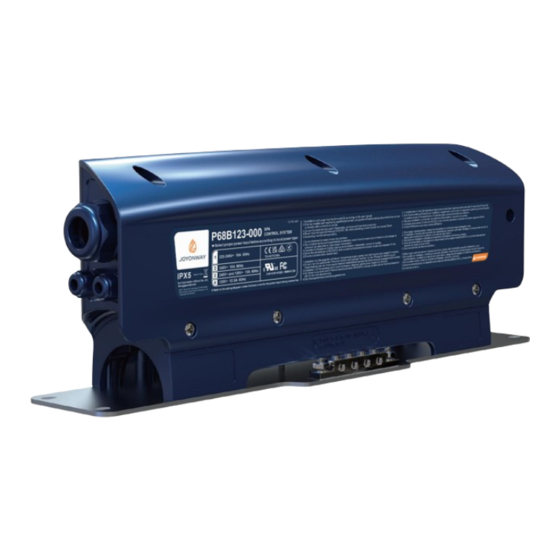
- Page 5 1、Product Overview Model:P68B123-000 Power input : 220-240V~ 10A 50Hz 240V~ 10A 60Hz 240V~ and 120V~ 10A 60Hz 120V~ 12.5A 60Hz Output: 1 set of ON/OFF type or RGB type SPA light (+5V/2A or +12/1A) 1 set of circ pump(2.0A) 1 set of ozone(0.2A) 1 set of heat pump (10.5A) Operating ambient temperature-20℃~55℃...
- Page 6 2、Product size 2.1、P68B123-000 Control system size and installation instructions 408.00 mm 88.00 mm [16.063"] [3.465"] P68B123-000 Control system rendering 390.00 mm [15.354"] 390.00 mm [15.354"] [17.638"] 448.00 mm The distance between the product and obstacles to be 20mm or more 4*Φ7.00 mm [0.27"] Reserved minimum space W: 128.00mm H: 166.00mm D: 448.00mm...
- Page 7 Installation instructions Installation instructions Fixing and installation P68B123-000 Power connection The exposed copper wire cannot be scattered M6*20 Screw (X 4pcs) M6 Washer (X 4pcs) (X 4pcs) M6 Spring washer M6 Nut (X 4pcs) 70mm 10-12mm Stripped length 10#Open PH2 Cross end wrench screwdriver 2、The distance between the product and the...
- Page 8 Installation instructions Wire installation Water droplet Water droplet Wrong way of wire installation, as shown in the above figure Water droplet Water droplet The product may work in a humid environment. Moisture may condense into water droplets or other leaks on the wires due to changes in temperature difference. Such water will flow a long the wires onto the product.
- Page 9 3、Basic information 3.1、Wiring diagram POWER INPUT AND LOAD OUTPUT PAY ATTENTION TO THE DIFFERENT CONNECTIONS BETWEEN J1/J2/J3 IN EACH POWER TYPE. CN10 LIGHTS POWER(12V / 5V POWER INPUT CIRC PUMP SANITIZING HEAT PUMP LIGHT 250V~/T10A CN10 CN22 T B1 CN23 WIRING P68B123-000 220 - 240V~ 4-L /...
- Page 10 3.2、Power Supply and Load POWER INPUT AND LOAD OUTPUT PAY ATTENTION TO THE DIFFERENT CONNECTIONS BETWEEN J1/J2/J3 IN EACH POWER TYPE. POWER INPUT CIRC PUMP SANITIZING HEAT PUMP LIGHT CN10 CN22 220 - 240V~ 4-L / 3(N/A) 4-L / 3(N/A) 4-L / 3(N/A) BROWN...
- Page 11 220-240V~ 10A 50HZ J2 - J3 POWER INPUT CIRC PUMP SANITIZING HEAT PUMP LIGHT CN10 CN22 220 - 240V~ 4-L / 3(N/A) 4-L / 3(N/A) 4-L / 3(N/A) BROWN 10A 50Hz BLUE 2-N / 1-G 2-N / 1-G 2-N / 1-G YE/GN J2 - J3 220-240V~ 0.2A...
- Page 12 240V~ 10A 60HZ J2 - J3 POWER INPUT CIRC PUMP SANITIZING HEAT PUMP LIGHT CN10 CN22 240V~ 4-L1 / 3(N/A) 4-L1 / 3(N/A) 4-L1 / 3(N/A) - L1 BLACK 10A 60Hz - L2 RED 2-L2 / 1-G 2-L2 / 1-G 2-L2 / 1-G GREEN J2 - J3...
- Page 13 240V~ and 120V~ 10A 60HZ J1 - J3 POWER INPUT CIRC PUMP SANITIZING HEAT PUMP LIGHT CN10 CN22 - N WHITE 240V~ and 120V~ 4-L1 / 3(N/A) 4-L1 / 3(N/A) 4-L1 / 3(N/A) - L1 BLACK 10A 60Hz 2-N / 1-G 2-N / 1-G 2-L2 / 1-G - L2 RED...
- Page 14 120V~ 12.5A 60HZ J2 - J3 POWER INPUT CIRC PUMP SANITIZING HEAT PUMP LIGHT CN10 CN22 120V~ 4-L / 3(N/A) 4-L / 3(N/A) 4-L / 3(N/A) BLACK 12.5A 60Hz 2-N / 1-G 2-N / 1-G 2-N / 1-G - N WHITE J2 - J3 - G GREEN 120V~ 1.5A...
- Page 15 3.3、Power supply configuration of the light The power configuration of the light is set according to the S2 table on the PCB board. CN10 250V~/T10A T B1 P68B123-000 Wiring Diagram Wiring Diagram CN23 CN22 LIGHT CN20 S.T W :When set upwards , the power output of the light is 12V :When set downwards , the power output of the light is 5V...
Need help?
Do you have a question about the Joyonway P68B123-000 and is the answer not in the manual?
Questions and answers