Table of Contents
Advertisement
Quick Links
SERVICE & OPERATING MANUAL
Original Instructions
Certified Quality
9.00
ISO 9001 Certified
ISO 14001 Certified
Warren Rupp, Inc.
A Unit of IDEX Corporation
800 N. Main St.,
Mansfield, Ohio 44902 USA
Telephone (419) 524.8388
Fax (419) 522.7867
SANDPIPERPUMP.COM
© Copyright 2017 Warren Rupp, Inc.
All rights reserved
Model MHDF1
229
& MHDF25
Heavy Duty Flap Valve
Design Level 2
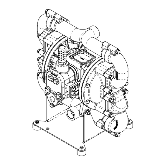
NOTE:
UNIT FURNISHED WITH SUB-BAS
AND RUBBER FEET AS STANDAR
STATIONARY BOLT DOWN USE,
FEET CAN BE REMOVED.
.
wa r r e n r u p p
c o m
Advertisement
Table of Contents

Related Manuals for Idex Warren Rupp MARATHON MHDF1


Summary of Contents for Idex Warren Rupp MARATHON MHDF1
- Page 1 & MHDF25 Heavy Duty Flap Valve Design Level 2 ISO 9001 Certified ISO 14001 Certified Warren Rupp, Inc. A Unit of IDEX Corporation 800 N. Main St., Mansfield, Ohio 44902 USA Telephone (419) 524.8388 Fax (419) 522.7867 SANDPIPERPUMP.COM © Copyright 2017 Warren Rupp, Inc.
- Page 2 Safety Information IMPORTANT WARNING When used for toxic or aggressive fluids, the pump should Read the safety warnings and instructions in this manual always be flushed clean prior to disassembly. before pump installation and start-up. Failure to comply with the recommendations stated in this manual could damage the pump and void factory warranty.
-
Page 3: Table Of Contents
Table of Contents SECTION 1: PUMP SPECIFICATIONS ....1 • Explanation of Nomenclature • Performance • Materials • Dimensional Drawings SECTION 2: INSTALLATION & OPERATION ..4 • Principle of Pump Operation • Recommended Installation Guide • Troubleshooting Guide SECTION 3: EXPLODED VIEW ......7 •... -
Page 4: Explanation Of Nomenclature
Explanation of Pump Nomenclature Your Model #: _____ (fill in from pump nameplate) Pump Pump Pump Discharge Diaphragm/ Design Options Construction Series Design Size Porting Valve Level XXXX, Model #: Pump Series Wet End Materials Construction HD Heavy Duty Nitrile Aluminum Wetted, Aluminum Air Neoprene Cast Iron Wetted, Aluminum Air... -
Page 5: Performance
Performance MHDF1/MHDF25 MODEL HDF1 Performance Curve SUCTION/DISCHARGE PORT SIZE Performance based on the following: elastomer fitted pump, flooded suction, AIR CONSUMPTION • MHDF1: 1” (25.4mm) NPT(F) water at ambient temperature. Average displacement per pump stroke: .10 Gallons (.38 Liters). SCFM (M 3 /hr) The use of other materials and varying hydraulic conditions may result in deviations in excess of 5%. -
Page 6: Dimensional Drawings
Dimensional Drawings MHDF1 & MHDF25 Heavy Duty Flap Valve Dimensions in inches (metric dimensions in brackets). Dimensional Tolerance .125" (3mm). "C" SUCTION PORT 1" FNPT (HDF1) "B" 1" BSPT (HDF25) 16.73 2.38 (OPTIONAL 90 "A" PORT ROTATION) AIR EXHAUST 3/4" FNPT 16.41 "D"... -
Page 7: Principle Of Pump Operation
Principle of Pump Operation Air-Operated Double Diaphragm (AODD) pumps are powered by compressed air or nitrogen. The main directional (air) control valve distributes ① compressed air to an air chamber, exerting uniform pressure over the inner surface of the diaphragm . -
Page 8: Recommended Installation Guide
Recommended Installation Guide Available Accessories: 1. Surge Suppressor In the event of a diaphragm rupture, pumped fluid can enter the air center section 2. Filter/Regulator of the pump and exit through the air exhaust port. When pumping hazardous fluids, it is recommended to pump the exhaust air to a safe location. 3. -
Page 9: Troubleshooting Guide
Troubleshooting Guide Symptom: Potential Cause(s): Recommendation(s): Pump Cycles Once Deadhead (system pressure meets or exceeds air Increase the inlet air pressure to the pump. Pump is designed for 1:1 pressure ratio at zero flow. supply pressure). (Does not apply to high pressure 2:1 units). Air valve or intermediate gaskets installed incorrectly. -
Page 10: Composite Repair Parts Drawing
Composite Repair Parts Drawing CAST IRON MID-SECTION Service & Repair Kits ASSEMBLY CONFIGURATION 475.283.000 Air End Conversion Kit 476.286.354 Wet End Kit (Converts from a Conductive Polypropylene Air Santoprene Diaphragms, Santoprene Flap Valves, Valve Assembly to the Die Cast Aluminun Air Valve EPDM HInge and Wear Pads, EPDM O-rings Assembly) Valve Body Assembly, Gaskets, and and Seals... -
Page 11: Composite Repair Parts List
Composite Repair Parts List Item Part Number Description Item Part Number Description 031.030.557 Assembly, Air Valve 530.036.000 Muffler (Cast Iron Center) 542.001.330 Nut, Square 031.203.000 Assembly, Air Valve 545.004.330 Nut, Hex, 5/16-18 070.012.170 Bearing, Sleeve 547.002.110 Nut, Stop 095.074.001 Pilot Valve Assembly 560.001.360 O-Ring 114.007.157... -
Page 12: Material Codes
Material Codes - The Last 3 Digits of Part Number 000..Assembly, sub-assembly; 364..EPDM Rubber 668..PTFE, FDA Santoprene /PTFE ® and some purchased items Color coded: BLUE • Delrin and Hytrel are registered 010..Cast Iron 365..Neoprene Rubber tradenames of E.I. DuPont. 015..Ductile Iron Color coded: GREEN •... -
Page 13: Air Distribution Valve Assembly
Air Distribution Valve Assembly With Aluminum Center Air Distribution Valve Servicing Main Air Valve Assembly Parts List See repair parts drawing, remove screws. Item Item Number Description Step 1: Remove hex capscrews (1E). 031.203.000 Assembly, Main Air Valve Step 2: Remove end cap (1D). 031.039.000 Sleeve &... - Page 14 Air Distribution Valve Assembly With Cast Iron Center Air Distribution Valve Servicing Main Air Valve Assembly Parts List See repair parts drawing, remove screws. Item Part Number Description 031.030.557 Assembly, Main Air Valve Step 1: Remove end cap retainer (1E). 031.039.000 Sleeve and Spool set Step 2: Remove end cap (1C).
-
Page 15: Pilot Valve Assembly
Pilot Valve Assembly Pilot Valve Servicing PILOT VALVE ASSEMBLY PARTS LIST With Pilot Valve removed from pump. Item Part Number Description Step 1: Remove snap ring (4F). 095.074.001 Pilot Valve Assembly Step 2: Remove sleeve (4B), inspect O-Rings (4C), 095.071.557 Pilot Valve Body 755.025.162 Pilot Valve sleeve... - Page 16 Diaphragm Service Drawing Diaphragm Service Drawing - with Overlay Diaphragm Service Drawing - One Piece Bonded warrenrupp • Model MHDF1/MHDF25 mhdf1dl2sm-rev0118...
-
Page 17: Diaphragm Servicing
Diaphragm Servicing Step 1: With manifolds and outer chambers Step 8: On opposite side of pump, thread the removed, remove diaphragm assemblies from remaining assembly onto the diaphragm rod. Using a diaphragm rod. DO NOT use a pipe wrench or similar torque wrench, tighten the assembly to the diaphragm tool to remove assembly from rod. - Page 18 Liquids - Common Safety Requirements, to verify conformance. October 20, 2005 Date of issue Signature of authorized person Director of Engineering Authorised Representative: Title IDEX Pump Technologies R79 Shannon Industrial Estate February 27, 2017 Shannon, Co. Clare, Ireland Date of revision Attn: Barry McMahon Revision Level: F...
- Page 19 Directive 94/9/EC (until April 19, 2016) and Directive 2014/34/EU (from April 20, 2016). Manufacturer: Applicable Standard: Warren Rupp, Inc. EN13463-1: 2001 A Unit of IDEX Corportion EN13463-5: 2003 800 North Main Street EN60079-25: 2004 P.O. Box 1568 Harmonised Standard:...
Need help?
Do you have a question about the Warren Rupp MARATHON MHDF1 and is the answer not in the manual?
Questions and answers