Table of Contents
Advertisement
Quick Links
Advertisement
Table of Contents
Troubleshooting

Related Manuals for Miller SubArc AC/DC


Summary of Contents for Miller SubArc AC/DC
- Page 1 OM-265364Q 2023-10 Processes Submerged Arc (SAW) Welding Electroslag (ESW) Welding Description Induction Heating Power Source SubArc AC/DC Digital, 1000 Amp, 1250 Digital CE OWNER’S MANUAL For product information, Owner’s Manual translations, and more, visit www.MillerWelds.com...
- Page 2 We know you don’t have time to do it any other way. That’s why when Niels Miller first started building arc welders in 1929, he made sure his products offered long-lasting value and superior quality.
-
Page 3: Table Of Contents
TABLE OF CONTENTS SECTION 1 – SAFETY PRECAUTIONS – READ BEFORE USING..............1 Symbol Usage . - Page 4 DECLARATION OF CONFORMITY for European Community (CE marked) products. MILLER Electric Mfg. LLC, 1635 West Spencer Street, Appleton, WI 54914 U.S.A. declares that the product(s) identified in this declaration conform to the essential requirements and provisions of the stated Council Directive(s), Commission Regulation(s) and Standard(s).
- Page 5 DECLARATION OF CONFORMITY For United Kingdom (UKCA marked) products. MILLER Electric Mfg. LLC, 1635 West Spencer Street, Appleton, WI 54914 U.S.A. declares that the product(s) identified in this declaration conform to the essential requirements and provisions of the stated Regulation(s) and Standard(s).
- Page 6 EMF DATA SHEET FOR ARC WELDING POWER SOURCE Product/Apparatus Identification Product Stock Number SUBARC AC/DC 1250 DIGITAL 907621 SUBARC AC/DC DIGITAL, 1000 AMP 907620 Compliance Information Summary Applicable regulation Directive 2014/35/EU Reference limits Directive 2013/35/EU, Recommendation 1999/519/EC Applicable standards IEC 62822−1:2016, IEC 62822−2:2016...
-
Page 8: Section 1 - Safety Precautions - Read Before Using
SECTION 1 – SAFETY PRECAUTIONS – READ BEFORE USING Protect yourself and others from injury—read, follow, and save these important safety precautions and operating instructions. 1-1. Symbol Usage DANGER! – Indicates a hazardous situation which, if not avoided, will result in death or serious injury. The possible hazards are shown in the adjoining symbols or explained in the text. - Page 9 HOT PARTS can burn. WELDING can cause fire or explosion. � Do not touch hot parts bare handed. � Allow cooling period before working on equipment. Welding on closed containers, such as tanks, drums, or pipes, can cause them to blow up. �...
-
Page 10: Additional Hazards For Installation, Operation, And Maintenance
� Never weld on a pressurized cylinder—explosion will result. CYLINDERS can explode if � Use only correct compressed gas cylinders, regulators, hoses, damaged. and fittings designed for the specific application; maintain them Compressed gas cylinders contain gas under high and associated parts in good condition. pressure. -
Page 11: California Proposition 65 Warnings
� To reduce possible interference, keep weld cables as short as ARC WELDING can cause possible, close together, and down low, such as on the floor. interference. � Locate welding operation 100 meters from any sensitive electronic equipment. � Electromagnetic energy can interfere with sensitive electronic equipment such as microprocessors, �... -
Page 12: Section 2 - Consignes De Sécurité - Lire Avant Utilisation
SECTION 2 – CONSIGNES DE SÉCURITÉ - LIRE AVANT UTILISATION Pour écarter les risques de blessure pour vous-même et pour autrui — lire, appliquer et ranger en lieu sûr ces consignes relatives aux précautions de sécurité et au mode opératoire. 2-1. - Page 13 � S’assurer que tous les panneaux et couvercles sont correctement LES ACCUMULATIONS DE GAZ en place. risquent de provoquer des blessures � Fixer le câble de retour de façon à obtenir un bon contact métal- ou même la mort. métal avec la pièce à souder ou la table de travail, le plus près possible de la soudure.
-
Page 14: Symboles De Dangers Supplémentaires En Relation Avec L'installation, Le Fonctionnement Et La Maintenance
� Brancher le câble de masse sur la pièce le plus près possible de � Les porteurs d’implants médicaux doivent consulter leur médecin la zone de soudage pour éviter le transport du courant sur une lon- et le fabricant du dispositif avant de s’approcher de la zone où se gue distance par des chemins inconnus éventuels en provoquant déroule du soudage à... - Page 15 � Affûter l'électrode au tungstène uniquement à la meuleuse dotée LIRE LES INSTRUCTIONS. de protecteurs. Cette manœuvre est à exécuter dans un endroit sûr lorsque l'on porte l'équipement homologué de protection du vi- � Lire et appliquer les instructions sur les étiquettes sage, des mains et du corps.
-
Page 16: Proposition Californienne 65 Avertissements
2-4. Proposition californienne 65 Avertissements AVERTISSEMENT – Ce produit peut vous exposer à des pro- Pour plus d’informations, consulter www.P65Warnings.ca.gov. duits chimiques tels que le plomb, reconnus par l’État de Californie comme cancérigènes et sources de malforma- tions ou d’autres troubles de la reproduction. 2-5. -
Page 17: Section 3 - Definitions
Do not discard product (where applicable) with general waste. conductor first. Connect black, white, and red wires (L1, L2, L3) to Safe119 2015 line terminals. Reuse or recycle Waste Electrical and Electronic Equipment (WEEE) by disposing at a designated collection facility. - Page 18 Turn off power before disassembling torch. Warning! Watch Out! There are possible hazards as shown by the symbols. Safe97 2012 05 Welding sparks can cause fires. Have a fire extinguisher nearby, and have a watchperson ready to use it. Protect yourself from electric shock by insulating yourself from work and ground. Use ventilating fan to remove fumes.
-
Page 19: Miscellaneous Symbols And Definitions
Always connect green, Or green with yellow stripe, wire to supply grounding terminal. Connect black, white, and red wires (L1, L2, L3) to line terminals. Safe101 2012 05 Turn power off before connecting to 115 volt receptacle. Turn power off before connecting to 115 volt receptacle. GND/PE, Ground/Protective Earth Safe 107 2012 09 Safe 114 2013 04... -
Page 20: Section 4 - Specifications
Information About Default Weld Parameters And Settings NOTICE – Each welding application is unique. Although certain Miller Electric products are designed to determine and default to certain typical welding parameters and settings based upon specific and relatively limited application variables input by the end user, such default settings are for reference purposes only;... -
Page 21: Static Characteristics
4-6. Static Characteristics The static (output) characteristics of the welding power source can be described as drooping during the SAW process. Static characteristics are also affected by control settings (including software), electrode, shielding gas, weldment material, and other factors. Contact the factory for spe- cific information on the static characteristics of the welding power source. -
Page 22: Duty Cycle And Overheating
E. China EEP Hazardous Substance Information 中国电器电子产品中有害物质的名称及含量 China EEP Hazardous Substance Information 部件名称 有害物质 Component Hazardous Substance Name 铅 汞 镉 六价铬 多溴联苯 多溴二苯醚 Do not spra (如果适用) PBDE (if applicable) 黄铜和铜部件 Brass and Cop- per Parts 耦合装置 Recycle or Coupling Devices 开关装置... -
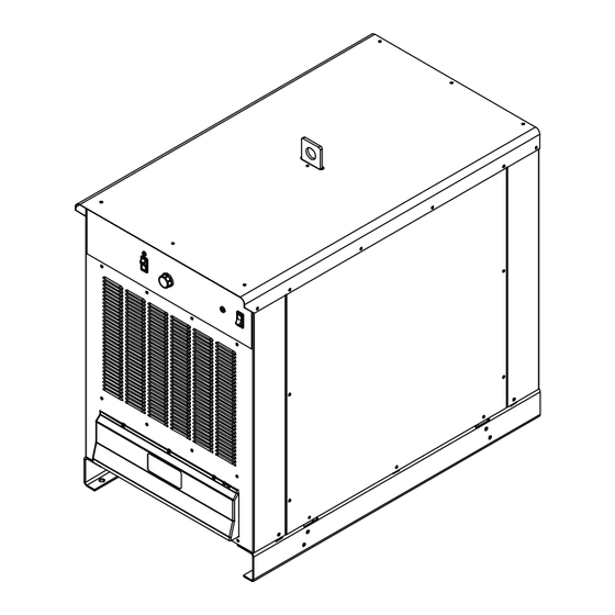
Page 23: Section 5 - Installation
42-1/4 in. (1073 mm) 15/16 in. (24 mm) 25-5/16 in. (643 mm) Weight SubArc AC/DC Digital, 1000 Amp − 1187 lb (538 kg) SubArc AC/DC 1250 Digital − 1260 lb (567 kg) 4 holes: 21/32 in. (6.5 mm) dia Front... -
Page 24: Selecting A Location
Writers: Remember to move unit dimension and weight and rating la- bel location information to the appropriate sections. 5-2. Selecting A Location 1-3. Selecting A Location nit dimension and weight and rating la- Do not move or operate unit where Movement it could tip. -
Page 25: Typical Equipment Location
5-3. Typical Equipment Location 1 Welding Power Source 2 Side Beam 3 SubArc Interface 4 Spool Support 5 Wire Drive Assembly 6 Torch Ref. 131138-A OM-265364 Page 18... -
Page 26: Electrical Service Guide
5-4. Electrical Service Guide A. Electrical Service Guide For SubArc AC/DC Digital, 1000 Amp Failure to follow these electrical service guide recommendations could create an electric shock or fire hazard. These recommen- dations are for an individual branch circuit sized for the rated output and duty cycle of one welding power source. In individual branch circuit installations, the National Electrical Code (NEC) allows the receptacle or conductor rating to be less than the rating of the circuit protection device. - Page 27 B. Electrical Service Guide For SubArc AC/DC Digital, 1250 Amp Failure to follow these electrical service guide recommendations could create an electric shock or fire hazard. These recommen- dations are for an individual branch circuit sized for the rated output and duty cycle of one welding power source. In individual branch circuit installations, the National Electrical Code (NEC) allows the receptacle or conductor rating to be less than the rating of the circuit protection device.
-
Page 28: Connecting Input Power
5-5. Connecting Input Power � See Section 5-6 for instructions. = GND/PE Earth Ground L1 (U) L2 (V) L3 (W) Terminal Block tools/ allen_wrench allen_set flathead tools/ pliers needlenose knife steelb GND/ PE Earth Ground allen_set flathead philips head wrench crescent wrench Ref. -
Page 29: Connecting Input Power (Continued)
5-6. Connecting Input Power (Continued) Select size and length of conductors using Connect input conductors L1 (U), L2 (V) and Installation must meet all National Section 5-5. Conductors must comply with L3 (W) to welding power source line and Local Codes − have only quali- national, state, and local electrical codes. -
Page 30: Matching Primary Lines L1, L2, And L3 When Using Multiple Ac Units
5-7. Matching Primary Lines L1, L2, And L3 When Using Multiple AC Units � See Section 5-8 for instructions. Set on AC Volts Scale Meter Polarity Does Not Matter Terminal Strip Terminal Strip Unit B (Second Unit) Unit A (First Unit) L1 (U) L2 (V) L3 (W) -
Page 31: Matching Primary Lines L1, L2, And L3 When Using Multiple Ac Units (Continued)
53 volts, swap L1 and L3. If the and unit previous to it. 5-9. Cable Routing Diagram 40 in. (1016 mm) 1 SubArc AC/DC Digital Series Welding 4 Interface Cable 7 Weld Cable Power Source 5 Torch 8 Work Cable... -
Page 32: Section 6 - System Connections
SECTION 6 – SYSTEM CONNECTIONS 6-1. Terminal Strip TE2 and Receptacle RC1 Information Socket On Terminal On Function Contact Information A, B 24 VAC. Protected by circuit breaker CB2. Electrical Input Power C, D 24 VAC common. +Accessory RS- 485 communication. Accessory Serial Communication -Accessory RS- 485 communication. -
Page 33: Terminal Strip Te1
6-2. Terminal Strip TE1 Turn off welding power source be- fore opening access door. 1 Access Hole Remove knockout or cover from access hole and install customer supplied strain relief. Route cable connections through the access hole. 2 12-Pole Terminal Strip 3 Label Remove and retain screws and open ter- minal strip panel. -
Page 34: Section 7 - Making Weld Output Connections
SECTION 7 – MAKING WELD OUTPUT CONNECTIONS 7-1. Weld Output Terminals And Selecting Cables Sizes* NOTICE – The Total Cable Length in Weld Circuit (see table below) is the combined length of both weld cables. For example, if the power source is 100 ft (30 m) from the workpiece, the total cable length in the weld circuit is 200 ft (2 cables x 100 ft). -
Page 35: Weld Output Terminals
7-2. Weld Output Terminals 265690-B output term1 2015−02 Turn off power before connecting to 1 Electrode Weld Output Terminals � For welding output terminal connec- weld output terminals. 2 Work Weld Output Terminals tions see Sections 7-4 thru 8-4. Do not use worn, damaged, under- sized, or repaired cables. -
Page 36: Work And Electrode Cable Connections For Single Dc Or Ac Arcs
7-4. Work And Electrode Cable Connections For Single DC or AC Arcs Connections To Work To Electrode Ref. 265690-A 3/4 in. (19 mm) philips head wrench crescent wrench Turn off welding power source be- more of the welding power source electrode �... -
Page 37: Section 8 - Basic Subarc (Saw) Welding
8-1. Basic SubArc SAW Equipment Connections Flux System SubArc Interface SubArc AC/DC Digital Series Flux Hopper Motor Extension Cable Wire Drive Assembly... -
Page 38: Remote Voltage Sensing Leads Placement Guidelines For A Single Arc (Required)
8-2. Remote Voltage Sensing Leads Placement Guidelines For A Single Arc (Required) Electrode Remote Voltage Sense Lead Work Remote Voltage Sense Lead Wire Drive Welding Power Sense lead is affected by weld Source current. Due to voltage drops across work piece, arc voltage may be low, causing need for deviation from standard procedures. -
Page 39: Sensing Lead Placement Guidelines For Multiple Arcs
8-3. Sensing Lead Placement Guidelines For Multiple Arcs Lead Wire Drive Welding Power Current flow from lead affects trail Source sense. Wire Electrode Remote Volt Drive Sense Leads Current flow from trail affects lead sense. Work Remote Voltage Neither sense lead picks up the cor- Sense Leads Lead rect work voltage, causing starting and... -
Page 40: Connecting Multiple Units
8-4. Connecting Multiple Units A. Tandem Connections LEAD UNIT TRAIL UNIT(S) (BLUE) (WHITE) (BLUE) (WHITE) TO WORK TO AC OUTPUT TO WORK ELECTRODE #2 TO AC OR DC OUTPUT ELECTRODE #1 TO RC3 ON NEXT AC UNIT WHITE BLUE Ref. 267377-A NOTICE –... -
Page 41: Section 9 - Power Source Operation
SECTION 9 – POWER SOURCE OPERATION 9-1. Front Panel Controls For CE And Non-CE Models 275814-A / Ref. 265690-A For remote control, connect remote device 4 Power Switch w/Indicator Light 1 Output Control Switch to remote receptacle RC1. Remote control 5 Status/Trouble LED provides full range of unit output regardless For weld output, place switch in On position. -
Page 42: Automation Interface Hardware Configuration (Plc Users Only)
9-2. Automation Interface Hardware Configuration (PLC Users Only) Table 9-2. Baud Rate Data Table 9-1. MODBUS Address DIP1 DIP1 Rate Address 9600 Default Setting 19200 38400 Default Setting reserved Table 9-3. Parity Data DIP1 Parity EVEN NONE Default Setting reserved Ref. -
Page 43: Section 10 - Plc Operation
SECTION 10 – PLC OPERATION 10-1. Connection To PLC The automation interface uses an RJ45 connector to communicate MODBUS RTU over RS485. � The RJ45 connector is NOT an Ethernet connection! The pin connections are as follows: Table 9-4. Connector Pinout Function RJ45 Pin Circuit... - Page 44 Table 9-7. Command Flags (MODBUS 101) Flag Name Bitmask Description Output Enable 0x0001 Enable Weld Output Wire Jog Up 0x0002 Feed Wire Up Wire Jog Down 0x0004 Feed Wire Down Flux On 0x0008 Open Flux Valve Motor CW 0x2000 Motor Direction (Clockwise=1) Automation Enable 0x4000 Enable Control From PLC...
- Page 45 Table 9-9. Status Flags (MODBUS 201) Flag Name Bitmask Description Valid Arc 0x0001 A valid arc has been detected. Output On 0x0002 The power source output is on. Run In 0x0004 The power source is in Run In. Weld 0x0008 The power source is in the weld state.
-
Page 46: Section 11 - Maintenance And Troubleshooting
SECTION 11 – MAINTENANCE AND TROUBLESHOOTING 11-1. SubArc System Help Codes SubArc Interface SubArc Power Source Fault Description Status/Trouble Light Digital Help Code � � Each flash sequence will be HELP will display in the followed by a one second upper display, and the code pause. - Page 47 4 Quick, 4 Slow Motor Low Bus Indicates bus voltage in SubArc Interface is low. 24 VAC from power source may be low if input primary line voltage is too low or, for DC power sources, power source could be incorrectly linked.
- Page 48 7 Quick, 1 Slow Invalid Model Type If paralleling units, firmware in controlling power source does not match firmware in the follow- ing power source. Update firm- ware in both machines to the latest revision. If code continues to display, contact nearest Fac- tory Authorized Service Agent.
-
Page 49: Routine Maintenance
11-2. Routine Maintenance Disconnect power before maintaining. � Service equipment more often if used in severe conditions. Maintenance Schedule Every 3 Months Every 6 Months Cords and Cables Visually Check condition of cords and cables. � Replace damaged cords and cables. Cracked Parts Replace damaged parts. -
Page 50: Accessing Supplementary Protector
11-4. Accessing Supplementary Protector Turn Off welding power source be- fore checking supplementary protector. 1 Supplementary Protector CB1 CB1 protects the 24 VAC portion of the Re- mote receptacle. Press button to reset breaker. 265690-A OM-265364 Page 43... -
Page 51: Troubleshooting Table
11-5. Troubleshooting Table Trouble Remedy No weld output; unit completely Place line disconnect switch in On position (see Section 5-5). inoperative. Check fuse F1 and replace if necessary (see Section 11-3). Check and replace line fuse(s), if necessary, or reset circuit breaker (see Section 5-5). Check for proper input power connections (see Section 5-5). -
Page 52: Section 12 - Electrical Diagrams
SECTION 12 – ELECTRICAL DIAGRAMS Figure 12-1. Circuit Diagram For AC/DC 1000/1250 Digital Series Models OM-265364 Page 45... - Page 53 Figure 12-2. Circuit Diagram For AC/DC 1000/1250 Digital Series Models OM-265364 Page 46...
- Page 54 Notes...
- Page 55 Effective January 1, 2023 (Equipment with a serial number preface of ND or newer) This limited warranty supersedes all previous Miller warranties and is exclusive with no other guarantees or war- ranties expressed or implied. LIMITED WARRANTY - Subject to the terms and...
- Page 56 Appleton, WI 54914 USA tact your distributor and/or equipment manu- facturer’s Transportation Department. International Headquarters–USA USA Phone: 920-735-4505 USA & Canada FAX: 920-735-4134 International FAX: 920-735-4125 For International Locations Visit www.MillerWelds.com ORIGINAL INSTRUCTIONS – PRINTED IN USA © Miller Electric Mfg. LLC 2023-10...
Need help?
Do you have a question about the SubArc AC/DC and is the answer not in the manual?
Questions and answers