Table of Contents
Advertisement
Quick Links
Advertisement
Table of Contents

Related Manuals for Nice MIGHTY MULE MM136


Summary of Contents for Nice MIGHTY MULE MM136
- Page 1 MM136 Wireless Gate Entry Intercom Wireless and Wired Installation Instructions...
-
Page 2: Table Of Contents
Table of Contents Wireless Gate Entry Intercom . . . . . . . . . . . . . . . . . . . . . . . . . . . . . . . . . . . . . . . . . . . . . . . . . . . . . . . . . . . . 3 Features of the Intercom/Keypad . -
Page 3: Wireless Gate Entry Intercom
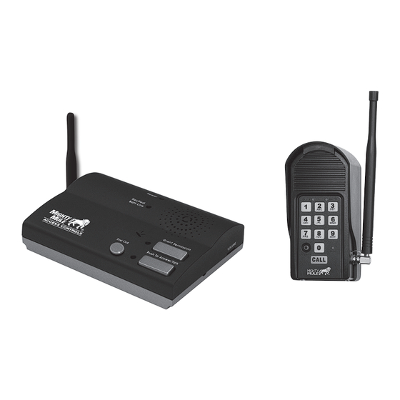
Wireless Gate Entry Intercom IMPORTANT: Allow the intercom base unit’s battery to charge for 12 hours before using the system for the first time. See page 18 for details. Keypad Unit Base Unit Crystal clear two-way communication up to 500 feet wireless . Thank you for purchasing the Mighty Mule Wireless Gate Entry Intercom . -
Page 4: Features Of The Intercom/Keypad
Features of the Intercom/Keypad The INTERCOM has two separate units . • The KEYPAD (outside unit) should be mounted outside the gate allowing the driver of the vehicle approaching the property to press the CALL button from their vehicle . •... -
Page 5: The Keypad
The Keypad Front Inside – 1 2 3 4 5 6 7 8 9 JUMPER RELAY AC/DC OUTPUT POWER IN ID SET RESET CALLING GRANTED – + – – – STATUS PROGRAM CALL... -
Page 6: Wireless Installation Of The Keypad
Wireless Installation of the Keypad NOTE: For wireless applications, the distance from the keypad to the opener’s receiver should not exceed 50 ft . Always test the keypad range before permanently mounting it in place. Learning the MM136 to an MM371, MM372, MM571 or MM572 Automatic Gate Opener LED1 LED2... -
Page 7: Learning A Mm136 To An Mm271 Or Mm272 Automatic Gate Opener
Wireless Installation of the Keypad LED1 LED2 LED3 Learning a MM136 to an MM271 or MM272 Automatic Gate Opener (A dip-switch type transmitter may be required) 1. Use the On/Off switch on the control box to power the system down . 2. -
Page 8: Wireless Installation Using The Dip Switches
Wireless Installation Using the DIP Switches Step 1: Mount the keypad cover using the screws provided . Set the keypad DIP switches to match your entry transmitter’s DIP switch settings . NOTE: If you have not changed your opener’s transmitter code from the factory setting, see the “Setting Your Personal Transmitter Code”... -
Page 9: Wired Installation Of The Keypad
Wired Installation of the Keypad NOTE: If you also plan to power the keypad with the gate opener’s power source, run two pairs of wires as described below . Run onne pair to hard-wire the keypad and the other pair to connect the keypad to the gate opener’s battery . - Page 10 Wired Installation of Keypad Step 5: Attach the wires from the keypad to the opener control board terminal blocks as shown in wiring diagrams below . Step 6: Replace the control board cover, and turn the power switch ON . Test the keypad by entering 1 2 3 4 . Step 7: Program your “Personal Master Code”...
-
Page 11: Control Board Connections
Control Board Connections NOTE: If your control board doesn’t look like any of these diagrams, please call Technical Service at 1-760- 438-7000 for additional support . Mighty Mule MM371, MM372, MM571, MM572 and TS571 Control Boards Connect #1 wire from the Connect #2 wire from the RELAY RELAY OUTPUT terminals OUTPUT terminals on the keypad to... -
Page 12: Mighty Mule 500 & 502 Control Boards
Control Board Connections Mighty Mule 500 & 502 Control Boards COM COM RECEIVER Connect the #2 wire from Connect the #1 wire from RELAY OUTPUT RELAY OUTPUT terminals on the terminals on the keypad keypad to the CYCLE terminal on one of the COMMON the opener control board. -
Page 13: Mm271 Control Boards
Control Board Connections MM271 Control Boards Connect #2 wire from the Connect #1 wire from the keypad to the COM RELAY OUTPUT terminals terminal on the gate on the keypad to the opener control board. CYCLE terminal on the gate opener control board. -
Page 14: Programming The Keypad
Programming the Keypad Programming Interface • All codes are four (4) digits in length . • Entry code is a four (4) digit code needed to activate the gate . • Master Code is needed to add, remove or reset entry codes . •... -
Page 15: Program (Add) New Temporary Entry Code
Programming the Keypad Program (Add) New Temporary Entry Code • Press and release PROGRAM button . • Enter the Master Code then press and release PROGRAM button . • Enter 8, and any number between 1 thru 7 then press and release the PROGRAM button . The number 1 thru 7 indicates the number of days after which the code will be automatically removed from memory . -
Page 16: Delete All Entry Codes
Programming the Keypad Delete ALL Entry Codes: • Press and release PROGRAM button . • Enter the Master Code, then press and release PROGRAM button . • Enter 0, 7, then press and release PROGRAM button . • Beeper beeps 3 times to confirm that the All Entry Codes are deleted. Example: Key press sequence to delete all entry codes from memory . -
Page 17: Intercom Description
Intercom Description Intercom - Face POWER Light: LED is GREEN when charging on AC power source and RED during battery power mode . Blinking RED indicates low battery on Base unit . KEYPAD BATTERY INDICATOR Light: LED turns ON when keypad battery is low . -
Page 18: Intercom Base Unit Installation
Intercom Base Unit Installation Connecting the Battery Remove the battery access cover using a small phillips head screwdriver . Plug the rechargeable Ni-MH battery into the receptacle inside the battery compartment . See diagram to the right . When this is done, replace the battery access cover . -
Page 19: Intercom Id Codes
Intercom ID Codes The Base and Keypad that came in this kit are programmed at the factory to communicate with each other, but do not need the ID Codes programmed . This Base is the MASTER or #1 unit . Adding Additional Base Units If you have purchased additional Base units to enhance your system, each additional unit’s ID Code must be programmed into the Keypad so they can communicate . -
Page 20: Troubleshooting
Troubleshooting Make sure all connections are secure and correct . Other electronic devices in the same area may interfere with the factory ID code . If the system does not communicate at all, reset the intercom/keypad ID code as follows . RESET ID: This will require two (2) people . -
Page 21: Keypad Specifications
Keypad Specifications 318MHz from keypad to gate opener Frequency 900MHz from keypad to base station Memory - Keypad Stores up to 25 four digit entry codes Power Consumption – Keypad 60ma when relay is closed Power Supply – Keypad 8-24 vdc or four AA batteries 9 vdc 300ma transformer;... -
Page 22: Fcc Warning
Nice North America’s cost . This warranty does not apply to damage to the product from negligence, abuse, abnormal usage, misuse, accidents, acts of god, normal wear and tear, failure to follow the manufacturer’s instructions, or arising from improper installation, storage or maintenance . -
Page 23: Hole Template For Mounting The Base Unit
Hole Template for Mounting the Base Unit... - Page 24 Mon-Fri 5am - 4pm PST • Saturday 7am - 3:30pm PST 5919 Sea Otter Place, Carlsbad, CA, 92010 www .mightymule .com ©2024 Nice North America LLC. Mighty Mule is a registered trademark of Nice North America LLC. All rights reserved. 10022724 Rev-C...
Need help?
Do you have a question about the MIGHTY MULE MM136 and is the answer not in the manual?
Questions and answers