
Related Manuals for ASROCK P4I45GV R5.0


Summary of Contents for ASROCK P4I45GV R5.0
- Page 1 P4i45GL P4i45GV User Manual Version 5.1a Published February 2004 Copyright©2004 ASRock INC. All rights reserved.
- Page 2 (including damages for loss of profits, loss of business, loss of data, interruption of business and the like), even if ASRock has been advised of the possibility of such damages arising from any defect or error in the manual or product.
-
Page 3: Table Of Contents
2.1 CPU Installation ............... 14 2.2 Installation of CPU fan and Heatsink ......14 2.3 Installation of Memory Modules (DIMM) ......15 2.4 Expansion Slots (PCI, AMR, and AGI Slots) ....16 2.5 Easy Dual Monitor Feature ..........17 2.6 Jumpers Setup ..............17 2.7 Onboard Headers and Connectors ........ -
Page 4: Introduction
ASRock’s commit- ment to quality and endurance. Chapter 1 and 2 of this manual contain introduction of the motherboard and step-by- step installation guide. Chapter 3 and 4 contain basic BIOS setup and support CD information. -
Page 5: Specifications
1.2 Specifications Platform: Micro ATX Form Factor: 9.6-in x 8.2-in, 24.4 cm x 20.8 cm ® ® CPU: Socket 478, supports Intel Pentium 4 (Prescott, Northwood, ® Willimate) / Celeron processor ® Chipsets: North Bridge (P4i45GL): Intel 845GL chipsets, standard FSB 400MHz (see CAUTION 1), Max. - Page 6 Because the installed AMR card will occupy the same external connecting position with the PCI card installed in “PCI3” slot, you will not be able to install any PCI card in “PCI3” slot if an A MR card has already been installed in the AMR slot.
- Page 7 P4i45GL may be fine tuned to support higher CPU front side bus frequencies on certain condition. Please refer to the table below for the details. CPU FSB Configuration Note P4i45GL 533 MHz 1. It supports DDR266 memory module at both DDR DIMM1 and DIMM2.
-
Page 8: Supported Agp Vga Cards List
PROLINK GF4-MX440 SPARKLE GF4-MX440 Gigabyte GV-AP64D Gigabyte GV-AP64D-H Gigabyte GV-AR64S-H POWERCOLOR RADEON 9000 POWERCOLOR RADEON 9100 TRANSCEND TS64MVDR7 SYNNEX GCM-SiS315EA32 For the latest updates of the supported AGP VGA cards list, please visit ASRock website for details. ASRock website: http://www.asrock.com/support/index.htm... - Page 9 Gigabyte GV R9000 PRO Gigabyte RADEON 9500 Gigabyte RADEON 9700 PRO POWER COLOR 9200 SAPHIRE RADEON 9200-128MB POWER COLOR XABRE600 For the latest updates of the supported AGP VGA cards list, please visit ASRock website for details. ASRock website: http://www.asrock.com/support/index.htm...
-
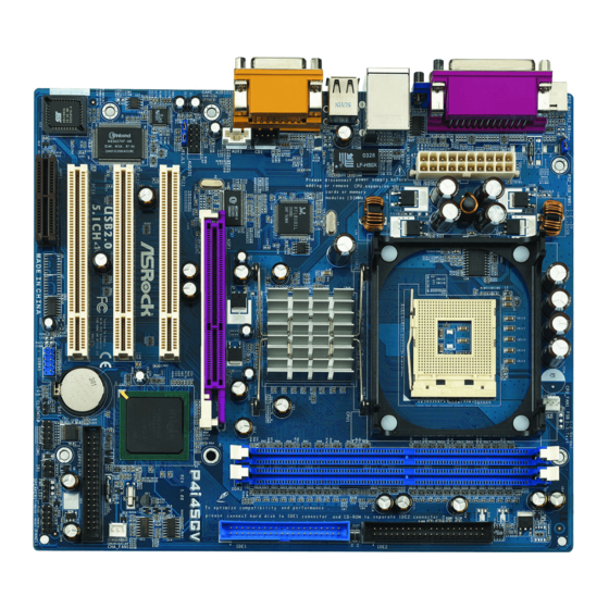
Page 10: Motherboard Layout
CPU Fan Connector (CPU_FAN1) USB 2.0 Header (USB45, Blue) North Bridge Controller AMR Slot (AMR1) 184-pin DDR DIMM Slots (DDR DIMM1- 2) BIOS FWH Chip Secondary IDE Connector (IDE2, Black) PCI Slots (PCI 1- 3) Primary IDE Connector (IDE1, Blue) - Page 11 CPU Fan Connector (CPU_FAN1) USB 2.0 Header (USB45, Blue) North Bridge Controller AMR Slot (AMR1) 184-pin DDR DIMM Slots (DDR DIMM1- 2) BIOS FWH Chip Secondary IDE Connector (IDE2, Black) PCI Slots (PCI 1- 3) Primary IDE Connector (IDE1, Blue)
-
Page 12: Asrock I/O
1.5 ASRock I/O Parallel Port Line Out (Lime) RJ-45 Port USB 2.0 Ports Game Port VGA Port Microphone (Pink) PS/2 Keyboard Port (Purple) Line In (Light Blue) PS/2 Mouse Port (Green) -
Page 13: Installation
Chapter 2 Installation P4i45GL/P4i45GV is a Micro ATX form factor (9.6-in x 8.2-in, 24.4 cm x 20.8 cm) motherboard. Before you install the motherboard, study the configuration of your chassis to ensure that the motherboard fits into it. Pre-installation Precautions Take note of the following precautions before you install motherboard compo- nents or change any motherboard settings. -
Page 14: Cpu Installation
CPU into the socket to avoid bending of the pins. Step 4. When the CPU is in place, press it firmly on the socket while you push down the socket lever to secure the CPU. The lever clicks on the side tab to indicate that it is locked. -
Page 15: Installation Of Memory Modules (Dimm)
DIMMs or the system components. Step 1. Unlock a DIMM slot by pressing the retaining clips outward. Step 2. Align a DIMM on the slot such that the notch on the DIMM matches the break on the slot. notch break... -
Page 16: Expansion Slots (Pci, Amr, And Agi Slots)
Because the installed A MR card will occupy the same external connecting position with the PCI card installed in “PCI3” slot, you will no be able to install any PCI card in “PCI3” slot if an AMR card has already been installed in the AMR slot. -
Page 17: Easy Dual Monitor Feature
(see p.10/p.11, No. 24) (see p.10/p.11, No. 23) Note: If the jumpers JL1 and JR1 are short (see the figure above), both the front panel and the rear panel audio connectors can work. Clear CMOS (CLRCMOS0, 2-pin Jumper) 2-pin Jumper (see p.10/p.11, No. -
Page 18: Onboard Headers And Connectors
FLOPPY1 (see p.10/p.11, No. 13) Pin1 the red-striped side to Pin1 Note: Make sure the red-striped side of the cable is plugged into Pin1 side of the connector. Primary IDE Connector (Blue) Secondary IDE Connector (Black) (39-pin IDE1, see p.10/p.11, No. 9) (39-pin IDE2, see p.10/p.11, No. - Page 19 AUX-R a CD-ROM, DVD/ROM, TV (AUX1: see p.10/p.11, No. 26) AUX1 AUX-L tuner card, or MPEG card. Front Panel Audio Header This is an interface for front +5VA BACKOUT-R panel audio cable that allows (9-pin AUDIO1) BACKOUT-L convenient connection and (see p.10/p.11, No.
-
Page 20: Bios Setup
BIOS FWH chip on the motherboard stores the BIOS Setup Utility. When you start up the computer, there is a chance for you to run the BIOS Setup. Press <F2> during the Power-On-Self-Test (POST) to enter the BIOS Setup Utility, otherwise, POST continues with its test routines. -
Page 21: Main Menu
Enter:Select Sub-Menu System Date [Month/Day/Year] Set the system date that you specify. Valid values for month, day, and year are Month: (Jan to Dec), Day: (1 to 31), Year: (up to 2099). Use keys to move between the Month, Day and Year fields. - Page 22 If the auto- detection fails, it may due to that the hard disk is too old or too new. If the hard disk was already formatted on an older system, the BIOS Setup may detect incorrect parameters.
-
Page 23: Advanced, Security, Power, Boot, And Exit Menus
LBA Mode This allows user to select the LBA mode for a hard disk > 512 MB under DOS and Windows; for Netware and UNIX user, select [Off] to disable the LBA mode. -
Page 24: Software Support
This motherboard supports various Microsoft Windows operating systems: 98 SE / ME / 2000 / XP. Because motherboard settings and hardware options vary, use the setup procedures in this chapter for general reference only. Refer to your OS documentation for more information. -
Page 25: Appendix
Microsoft Windows ® ® XP. Set to [Auto] if using Microsoft Windows XP, or Linux kernel version 2.4.18 or higher. This option will be hidden if the current CPU does not support Hyper-Threading technology. - Page 26 F10:Save & Exit Enter:Select Sub-Menu AGP Aperture Size: It refers to a section of the PCI memory address range used for graphics memory. We recommend that you leave this field at the default value unless your AGP card requires other sizes.
- Page 27 OnBoard Serial Port: Use this to set addresses for the onboard serial ports or disable serial ports. Configuration options: [Auto], [Disabled], [3F8 / IRQ4 / COM1], [2F8 / IRQ3 / COM2], [3E8 / IRQ4 / COM3], [2E8 / IRQ3 / COM4]. OnBoard Infrared Port: You may select [Auto] or [Disabled] for this onboard...
- Page 28 Configuration options: [Auto], [Disabled], [378], [278]. Parallel Port Mode: Set the operation mode of the parallel port. The default value is [ECP+EPP]. If this option is set to [ECP+EPP], it will show the EPP version in the following item, “EPP Version”.
-
Page 29: Security Setup Menu
Set User Password: Press <Enter> to set User Password. Valid password can be a 1 to 8 alphanumeric characters combination. If you already have a password, you must enter your current password first in order to create a new p assword. -
Page 30: Power Setup Menu
Ring-In Power On: Use this to enable or disable Ring-in signals to turn on the system from the power-soft-off mode. PCI Devices Power On: Use this to enable or disable PCI devices to turn on the system from the power-soft-off mode. -
Page 31: Boot Setup Menu
F10:Save & Exit :Select Menu Enter:Select Sub-Menu Quick Boot Mode: Enable this mode will speed up the boot-up routine by skipping memory retestings. Boot Up Num-Lock: If this is enabled, it will automatically activate the Numeric Lock function after boot-up. -
Page 32: Exit Menu
BIOS Setup Utility without making any changes to the settings. Load Default Settings: After you enter the submenu, the message “Load default settings” will appear. If you press <Enter>, it will load the default values for all the setup configuration.
Need help?
Do you have a question about the P4I45GV R5.0 and is the answer not in the manual?
Questions and answers