Table of Contents
Advertisement
Quick Links
Download this manual
See also:
Installation Manual
Advertisement
Table of Contents

Related Manuals for ASROCK K8NF6G-VSTA

Summary of Contents for ASROCK K8NF6G-VSTA
-
Page 1: User Manual
K8NF6G-VSTA User Manual Version 1.0 Published July 2006 Copyright©2006 ASRock INC. All rights reserved. 1 1 1 1 1... - Page 2 (including damages for loss of profits, loss of business, loss of data, interruption of business and the like), even if ASRock has been advised of the possibility of such damages arising from any defect or error in the manual or product.
-
Page 3: Table Of Contents
Serial ATA (SATA) / Serial ATAII (SATAII) Hard Disks Installation ................. 23 2.10 Hot Plug and Hot Swap Functions for SATA / SATAII HDDs ..23 2.11 Driver Installation Guide ............23 2.12 HDMR Card and Driver Installation ..........24 2.13 Installing Windows... - Page 4 Hardware Health Event Monitoring Screen ......38 Boot Screen ................39 3.5.1 Boot Settings Configuration ........... 39 Security Screen ................ 40 Exit Screen ................41 4 . 4 . 4 . 4 . 4 . Software Support Software Support Software Support Software Support Software Support ...........
-
Page 5: Introduction Introduction
ASRock’s commit- ment to quality and endurance. In this manual, chapter 1 and 2 contain introduction of the motherboard and step-by- step guide to the hardware installation. Chapter 3 and 4 contain the configuration guide to BIOS setup and information of the Support CD. -
Page 6: Specifications
Specifications Specifications Specifications Specifications Specifications - Micro ATX Form Factor: 9.6-in x 8.2-in, 24.4 cm x 20.8 cm Platform - Socket 754 for AMD Athlon 64 and Sempron Processors - Supports AMD’s Cool ‘n’ Quiet Technology (see CAUTION 1) - Chipset capable to FSB 1000 MHz (2.0 GT/s) - Page 7 - 2 x Serial ATAII 3.0Gb/s connectors, support RAID (RAID 0, Connector RAID 1, JBOD), NCQ, and “Hot Plug” functions (see CAUTION 7) - 1 x ATA133 IDE connector (supports 2 x IDE devices) - 1 x Floppy connector - 1 x IR header...
- Page 8 8-channel modes. Please check the table on page 11 for proper connection. Before installing SATAII hard disk to SATAII connector, please read the “SATAII Hard Disk Setup Guide” on page 22 to adjust your SATAII hard disk drive to SATAII mode. You can also connect SATA hard disk to SATAII connector directly.
-
Page 9: Vista
VGA that we suggest. Sempron 2500+ Memory 512MB Single Channel* DX9.0 with WDDM Driver * If you use onboard VGA with total system memory size 512MB and plan to submit Windows Vista Basic logo, please adjust the shared memory size of ®... -
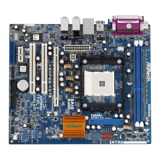
Page 10: Motherboard Layout
RESET FLOPPY1 PS2_USB_PW1 Jumper Floppy Connector (FLOPPY1) CPU Fan Connector (CPU_FAN1) Clear CMOS Jumper (CLRCMOS1) 184-pin DDR DIMM Slots (DDR1- 2) Game Port Header (GAME1) Primary SATAII Connector (SATAII_1, Red) Flash Memory Secondary SATAII Connector (SATAII_2, Red) HDMR Slot (HDMR1) -
Page 11: Hd 8Ch I/O
PS/2 Mouse Port (Green) Front Speaker (Lime) If you use 2-channel speaker, please connect the speaker’s plug into “Front Speaker Jack”. See the table below for connection details in accordance with the type of speaker you use. TABLE for Audio Output Connection... -
Page 12: Installation Installation
Installation Installation Installation K8NF6G-VSTA is a Micro ATX form factor (9.6-in x 8.2-in, 24.4 cm x 20.8 cm) motherboard. Before you install the motherboard, study the configuration of your chassis to ensure that the motherboard fits into it. Pre-installation Precautions... -
Page 13: Cpu Installation
Step 4. When the CPU is in place, press it firmly on the socket while you push down the socket lever to secure the CPU. The lever clicks on the side tab to indicate that it is locked. -
Page 14: Installation Of Memory Modules (Dimm)
DIMMs or the system components. Step 1. Unlock a DIMM slot by pressing the retaining clips outward. Step 2. Align a DIMM on the slot such that the notch on the DIMM matches the break on the slot. notch break... -
Page 15: Expansion Slots (Pci Express, Pci, And Hdmr Slots)
(PCI Express Slots, PCI Slots and HDMR Slot) (PCI Express Slots, PCI Slots and HDMR Slot) There are 2 PCI Express slots, 2 PCI slots and 1 HDMR slot on K8NF6G-VSTA motherboard. PCIE Slots: PCIE1 (PCI Express Graphics slot) is used for PCI Express cards with x16 lane width graphics cards. -
Page 16: Easy Multi Monitor Feature
This motherboard supports Multi Monitor upgrade. With the internal onboard VGA and the external add-on PCI Express VGA card, you can easily enjoy the benefits of Multi Monitor feature. Please refer to the following steps to set up a multi monitor environment: 1. -
Page 17: Jumpers Setup
CLRCMOS1 for 5 seconds. However, please do not clear the CMOS right after you update the BIOS. If you need to clear the CMOS when you just finish updating the BIOS, you must boot up the system first, and then shut it down... -
Page 18: Onboard Headers And Connectors
(33-pin FLOPPY1) FLOPPY1 Pin1 (see p.10 No. 15) the red-striped side to Pin1 Note: Make sure the red-striped side of the cable is plugged into Pin1 side of the connector. Primary IDE connector (Blue) (39-pin IDE1, see p.10 No. 6) IDE1... - Page 19 HDA to function correctly. Please follow the instruction in our manual and chassis manual to install your system. 2. If you use AC’97 audio panel, please install it to the front panel audio header as below: A. Connect Mic_IN (MIC) to MIC2_L.
- Page 20 Though this motherboard provides 4-Pin CPU fan (Quiet Fan) support, the 3-Pin CPU fan still can work successfully even without the fan speed control function. If you plan to connect the 3-Pin CPU fan to the CPU fan connector on this motherboard, please connect it to Pin 1-3.
- Page 21 Game Port Header Connect a Game cable to this JBB1 header if the Game port bracket (15-pin GAME1) MIDI_OUT is installed. (see p.10 No. 17) JBB2 MIDI_IN JAB2 JAB1 Serial port Header This COM1 header RRXD1 DDTR#1 supports a serial port module.
-
Page 22: Sataii Hard Disk Setup Guide
Before installing SATAII hard disk to your computer, please carefully read below SATAII hard disk setup guide. Some default setting of SATAII hard disks may not be at SATAII mode, which operate with the best performance. In order to enable SATAII function, please follow the below instruction with different vendors to correctly adjust your SATAII hard disk to SATAII mode in advance;... -
Page 23: Installation
STEP 2: Connect the SATA power cable to the SATA / SATAII hard disk. STEP 3: Connect one end of the SATA data cable to the motherboard’s SATAII connector. STEP 4: Connect the other end of the SATA data cable to the SATA / SATAII hard disk. 2.10 2.10... -
Page 24: Hdmr Card And Driver Installation
If you do not insert HDMR card to this motherboard, and you finish installing all drivers to your system now, but in the future, you plan to use HDMR card function on this motherboard, please follow the steps below then. -
Page 25: Untied Overclocking Technology
Untied Overclocking function, please enter “Overclock Mode” option of BIOS setup to set the selection from [Auto] to [CPU, PCIE, Async.]. Therefore, CPU FSB is untied during overclocking, but PCI / PCIE buses are in the fixed mode so that FSB can operate under a more stable overclocking environment. -
Page 26: Introduction
Power-On-Self-Test (POST) to enter the BIOS SETUP UTILITY, otherwise, POST will continue with its test routines. If you wish to enter the BIOS SETUP UTILITY after POST, restart the system by pressing <Ctl> + <Alt> + <Delete>, or by pressing the reset button on the system chassis. -
Page 27: Bios Setup Utility
To jump to the Exit Screen or exit the current screen <ESC> Main Screen Main Screen Main Screen Main Screen Main Screen When you enter the BIOS SETUP UTILITY, the Main screen will appear and display the system overview. BIOS SETUP UTILITY Advanced H/W Monitor Boot Security... -
Page 28: Advanced Screen
Advanced Screen Advanced Screen Advanced Screen Advanced Screen In this section, you may set the configurations for the following items: CPU Configuration, Chipset Configuration, ACPI Configuration, IDE Configuration, PCIPnP Configuration, Floppy Configuration, SuperIO Configuration, and USB Configuration. BIOS SETUP UTILITY... - Page 29 It will display Processor Maximum Voltage for reference. Multiplier/Voltage Change This item is set to [Auto] by default. If it is set to [Manual], you may adjust the value of Processor Multiplier and Processor Voltage. However, it is recom- mended to keep the default value for system stability.
- Page 30 [1T]. The default value is [Auto]. Burst Length Burst length can be set to 8, 4 or 2 beats. 64 Bit Dq must use the 4 beats. Bank Interleaving Interleaving allows memory accesses to be spread out over banks on the...
-
Page 31: Chipset Configuration
Primary Graphics Adapter This item will switch the PCI Bus scanning order while searching for video card. It allows you to select the type of Primary VGA in case of multiple video controllers. The default value of this feature is [PCI]. Configuration options: [PCI], [Onboard] and [PCI Express]. -
Page 32: Acpi Configuration
Use this item to enable or disable Ring-In signals to turn on the system from the power-soft-off mode. PCI Devices Power On Use this item to enable or disable PCI devices to turn on the system from the power-soft-off mode. PS/2 Keyboard Power On Use this item to enable or disable PS/2 keyboard to turn on the system from the power-soft-off mode. -
Page 33: Ide Configuration
[non-RAID]. If you want to operate RAID function on SATA / SATAII HDDs, please select [RAID]. * If you select [RAID] mode, SATA / SATAII HDDs can not be accessed until you finish configuring RAID functions in NVIDIA BIOS / Windows RAID Utility. - Page 34 [ARMD]: This is used for IDE ARMD (ATAPI Removable Media Device), such as MO. LBA/Large Mode Use this item to select the LBA/Large mode for a hard disk > 512 MB under DOS and Windows; for Netware and UNIX user, select [Disabled] to disable the LBA/Large mode.
-
Page 35: Pcipnp Configuration
Use this item to enable or disable the S.M.A.R.T. (Self-Monitoring, Analysis, and Reporting Technology) feature. Configuration options: [Disabled], [Auto], [Enabled]. 32Bit Data Transfer Use this item to enable 32-bit access to maximize the IDE hard disk data transfer rate. 3.3.5 3.3.5 3.3.5 PCIPnP Configuration... -
Page 36: Floppy Configuration
Use this item to enable or disable floppy drive controller. Serial Port Address Use this item to set the address for the onboard serial port or disable it. Configuration options: [Disabled], [3F8 / IRQ4], [2F8 / IRQ3], [3E8 / IRQ4], [2E8 / IRQ3]. -
Page 37: Usb Configuration
Parallel Port Address Use this item to set the address for the onboard parallel port or disable it. Configuration options: [Disabled], [378], and [278]. Parallel Port Mode Use this item to set the operation mode of the parallel port. The default value is [ECP+EPP]. -
Page 38: Hardware Health Event Monitoring Screen
Hardware Health Event Monitoring Screen Hardware Health Event Monitoring Screen In this section, it allows you to monitor the status of the hardware on your system, including the parameters of the CPU temperature, motherboard temperature, CPU fan speed, chassis fan speed, and the critical voltage. -
Page 39: Boot Screen
Boot Screen Boot Screen Boot Screen Boot Screen Boot Screen In this section, it will display the available devices on your system for you to config- ure the boot settings and the boot priority. BIOS SETUP UTILITY Main Advanced H/W Monitor... -
Page 40: Security Screen
Security Screen Security Screen Security Screen Security Screen Security Screen In this section, you may set or change the supervisor/user password for the system. For the user password, you may also clear it. BIOS SETUP UTILITY Main Advanced H/W Monitor... -
Page 41: Exit Screen
BIOS SETUP UTILITY. Discard Changes and Exit When you select this option, it will pop-out the following message, “Dis- card changes and exit setup?” Select [OK] to exit the BIOS SETUP UTILITY without saving any changes. Discard Changes When you select this option, it will pop-out the following message, “Dis-... -
Page 42: Software Support Software Support
4.2.1 Running The Support CD 4.2.1 Running The Support CD To begin using the support CD, insert the CD into your CD-ROM drive. The CD automatically displays the Main Menu if “AUTORUN” is enabled in your computer. If the Main Menu did not appear automatically, locate and double click on the file “ASSETUP.EXE”... -
Page 43: Appendix: Amd's Cool 'N' Quiet
AMD’s Cool ‘n’ Quiet AMD’s Cool ‘n’ Quiet echnology echnology For power-saving sake, it is strongly recommended to enable AMD’s Cool ‘n’ Quiet technology under Windows system. When using this feature, please make sure to ® install “AMD Processor Driver” from the “Support CD” first.
Need help?
Do you have a question about the K8NF6G-VSTA and is the answer not in the manual?
Questions and answers