Advertisement
Quick Links
QUICK START MANUAL
Applicable For RM-CEM Actuators
With Stand-alone Controller
(Please read this MANUAL before use.)
More Technical Support
• MODBUS Communication Parameters
• CANOPEN Communication Parameters
• Secondary Development SDK and Interface Parameters
Please Visit the Website: https://doc.rmaxis.com
Customer Service / After Sales Hotline: +86 0757 2220 5682
Website (Product Information Download): www.rmaxis.com
Foshan Augmented Intelligence Technology Co.,Ltd
Advertisement

Related Manuals for ROBUSTMOTION RM-CEM


Summary of Contents for ROBUSTMOTION RM-CEM
- Page 1 QUICK START MANUAL Applicable For RM-CEM Actuators With Stand-alone Controller (Please read this MANUAL before use.) More Technical Support • MODBUS Communication Parameters • CANOPEN Communication Parameters • Secondary Development SDK and Interface Parameters Please Visit the Website: https://doc.rmaxis.com Customer Service / After Sales Hotline: +86 0757 2220 5682 Website (Product Information Download): www.rmaxis.com...
- Page 2 MODEL:RM-MGBD-08-8 Match MGBD 123** MGBD 123** Model Label on the RM-CEM Controller Model Label on the RM Actuator 3 . Extra Items Prepared by User 1) Output power supply: DC24V±10%; please refer to the controller label for Rated Current .
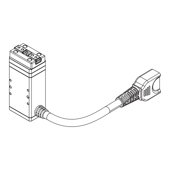
- Page 3 B. Wiring of Actuators Depending on the product design of different product models, or different optional cable connectors selected by user, you may receive the following types of and cable. Please follow the corresponding guidelines for wiring of actuators. 1. Actuator with Extended Cable ➀...
- Page 4 2. Actuators with Fixed Connector Downward Rightward Upward Leftward Standard fi xed terminal block. Interface terminals can be reoriented by need. Cables for Connection Both two types of cables support the above-mentioned actuator with fi xed connector. Standard connector Optional connector (with injection protection) (without injection protection) Correctly Tie the Cables...
- Page 5 C. Connection of the RM Actuator to the Controller CN4 Connector CN3 Connector CN2 Connector RM-CEM D. Description of the Controller Bus Connection RJ45 Plug Function Identifi cation RJ45 Function RJ45 - Connector RJ45-1 485-SGA RJ45-2 485-SGB RJ45-3 RJ45-4 485-VCC-5V*...
- Page 6 E. Wiring Instructions for Power Supply and Emergency Stop Witch 1. Power Supply Wiring Method Please keep EMG-KM1 and EMG-KM2 shorted. 24v Power Please note the orientation of the terminals shown. 2. Motor Emergency Stop Switch Wiring Method STOP Emergency Stop Switch 3.
- Page 7 2) Modbus_TCP a. Please select ' ' as the connection type and click 'Next'. b. Please enter the device IP address as '192.168.0.233' (the default factory setting is 192.168.0.233). c. Please enter '502' as the device port number (the default factory setting is 502). d.
- Page 8 It is recommended to set the force range for the pressing motion between 30% and 100%. 6. Return to Origin Setting The actuator has been set to automatically return to the origin by default before leaving the factory; generally, no manual operation is required after the actuator is powered on again (when the movement command is executed after powering on, the system will first determine whether it has returned to the origin;...
- Page 9 8. Controller Location Assignment Output Enter Signal Type of Input Variables Output Variable Variable Address Data Address in_position in place IO control enable signal Reset error Alarm Servo switch Servo feedback signal Return to origin Reserve Location out of Reserve tolerance Reserve Speed is too bad...
-
Page 10: Frequency Of Maintenance
2. Frequency of Maintenance Regularly check Regular check of Regular grease the tightness of the transmission parts replenishment connecting screws ○ First time of use After one month ○ ○ of operation After six months ○ ○ ○ of operation After one year of ○...
Need help?
Do you have a question about the RM-CEM and is the answer not in the manual?
Questions and answers