Advertisement
Quick Links
QUICK START MANUAL
Applicable for RM-CEU Actuators
With Stand-alone Controller
(Please read this MANUAL before use.)
More Technical Support
• MODBUS Communication Parameters
• CANOPEN Communication Parameters
• Secondary Development SDK and Interface Parameters
Please Visit the Website: https://doc.rmaxis.com
Customer Service / After Sales Hotline: +86 0757 2220 5682
Website (Product Information Download): www.rmaxis.com
Foshan Augmented Intelligence Technology Co.,Ltd
Advertisement

Related Manuals for ROBUSTMOTION RM-CEU Series


Summary of Contents for ROBUSTMOTION RM-CEU Series
- Page 1 QUICK START MANUAL Applicable for RM-CEU Actuators With Stand-alone Controller (Please read this MANUAL before use.) More Technical Support • MODBUS Communication Parameters • CANOPEN Communication Parameters • Secondary Development SDK and Interface Parameters Please Visit the Website: https://doc.rmaxis.com Customer Service / After Sales Hotline: +86 0757 2220 5682 Website (Product Information Download): www.rmaxis.com Foshan Augmented Intelligence Technology Co.,Ltd...
- Page 2 1. Preparation 1 . Are The Products Complete? Please check whether the model and quantity of the product received inside the package corresponds to the "Sales Delivery Sheet". SAMPLE Sales Delivery Sheet Client Name:xxx Co.Ltd Delivery Date:2022-08-08 Contact Person:Zhang Xiaoming Serial Num:xxxx xxxxx Contact Num:xxx xxxx xxxx Remark:xxx...
- Page 3 2. Wiring Of Actuators Depending on the product design of different product models, or different optional cable connectors selected by user, you may receive the following types of and cable. Please follow the corresponding guidelines for wiring of actuators. Hot Plugging Is Prohibited. The power supply and cable of the Actuator cannot be hot plugging while it's working, which will cause damage to both the Actuator and controller.
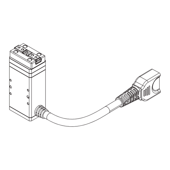
- Page 4 2 . Actuators With Fixed Connector Downward Rightward Upward Leftward Standard fixed terminal block. Interface terminals can be reoriented by need. Cables For Connection Both two types of cables support the above-mentioned actuator with fixed connector. Standard Connector Optional Connector (With Injection Protection) (Without Injection Protection) Cables For Connection...
- Page 5 3.Connection Of The RM Actuator To The Controller (CN4 Connector) 1 : A L A R M 2 : S E R V O 3 : P O W E R K 1 : P U L I / O U F W ...
- Page 6 2. Use The RM-CEU-X-TCP Controller With The Following Connections: CN8 and CN9 support blind insertion. RJ45 Function RJ45 - Connector RJ45-1 485-SGA RJ45-2 485-SGB RJ45-3 CAN_H 1 : A L A R M 2 : S E R V O 3 : ...
- Page 7 5.Controller I/O, Pulse Wiring Instructions 1. SCSI (CN6 Connector), K1 Terminal Description K1 Terminal Description Example - (1) I/O (2) PULSE (3) I/O Valid Pulse Please Keep I/O Invalid Pulse Invalid SCSI-26PIN Connector CN6 Connector Defination Definition OUT-DO PUL-5V-P OUT-SO PUL-24V-P OUT-D1 PUL-5V-N...
- Page 8 2) The pulses are wired as shown in the diagram. In-0 is defined as return to home, out-0 is defined as returned to home, out-1 is defined as pulse in place signal. 5. Pulse Control Process Waiting For The Send Origin Waiting For A Pulse In Place Pulsing...
-
Page 9: Software Installation
2 . Motor Emergency Stop Switch Wiring Method STOP Emergency Stop Switch 3 . Controller Indicator Description Status Green Light On Yellow Light On Red Light On DescriptionNormal Power On Servo On Run Alarm 7.RM Control Software Platform 1. When the actuator is powered on in the right way, the controller's indicator lights will light up as shown on the right . - Page 10 When a menu bar appears on the left (as shown in the red box below), it means the actuator has been successfully connected. You can close the 'Device Connection' object after all devices have been connected, When the software is connected to the controller, the current parameters in the controller will be automatically read.
- Page 11 6. Description of Point Motion Modes Absolute Motion The distance of the target position from the origin point. Target Location The position that needs to be absolutely moved. Speed The speed of movement (default 30mm/s). Acceleration and The acceleration and deceleration of movement Deceleration (default 500mm/s Define the in-position signal giving range (default 0.1mm, i.e.
-
Page 12: Frequency Of Maintenance
8.Quick Guide To Maintenance 1.Overviews 1) Use For the First Time For the first time of usage, please check whether the interval from the date of receipt to the date of first use is more than 15 days (duration should be shorter in winter). If yes, it is recommended to spray a small amount of WD-40 high efficiency white lithium grease on the screws, guide rails , and other transmission parts of the Actuator before use.
Need help?
Do you have a question about the RM-CEU Series and is the answer not in the manual?
Questions and answers