Table of Contents
Advertisement
Available languages
Available languages
Quick Links
Download this manual
See also:
User Manual
Copyright Notice:
Copyright Notice:
Copyright Notice:
Copyright Notice:
Copyright Notice:
No part of this installation guide may be reproduced, transcribed, transmitted, or trans-
lated in any language, in any form or by any means, except duplication of documen-
tation by the purchaser for backup purpose, without written consent of ASRock Inc.
Products and corporate names appearing in this guide may or may not be registered
trademarks or copyrights of their respective companies, and are used only for identifica-
tion or explanation and to the owners' benefit, without intent to infringe.
Disclaimer:
Disclaimer:
Disclaimer:
Disclaimer:
Disclaimer:
Specifications and information contained in this guide are furnished for informational
use only and subject to change without notice, and should not be constructed as a
commitment by ASRock. ASRock assumes no responsibility for any errors or omissions
that may appear in this guide.
With respect to the contents of this guide, ASRock does not provide warranty of any kind,
either expressed or implied, including but not limited to the implied warranties or
conditions of merchantability or fitness for a particular purpose. In no event shall
ASRock, its directors, officers, employees, or agents be liable for any indirect, special,
incidental, or consequential damages (including damages for loss of profits, loss of
business, loss of data, interruption of business and the like), even if ASRock has been
advised of the possibility of such damages arising from any defect or error in the guide
or product.
This device complies with Part 15 of the FCC Rules. Operation is subject to the
following two conditions:
(1) this device may not cause harmful interference, and
(2) this device must accept any interference received, including interference that
may cause undesired operation.
CALIFORNIA, USA ONLY
The Lithium battery adopted on this motherboard contains Perchlorate, a toxic
substance controlled in Perchlorate Best Management Practices (BMP) regulations
passed by the California Legislature. When you discard the Lithium battery in
California, USA, please follow the related regulations in advance.
"Perchlorate Material-special handling may apply, see
www.dtsc.ca.gov/hazardouswaste/perchlorate"
ASRock Website: http://www.asrock.com
Copyright©2010 ASRock INC. All rights reserved.
ASRock H55 Extreme3 Motherboard
Published March 2010
1 1 1 1 1
Advertisement
Table of Contents

Subscribe to Our Youtube Channel
Related Manuals for ASROCK H55 EXTREME3


Summary of Contents for ASROCK H55 EXTREME3
- Page 1 ASRock. ASRock assumes no responsibility for any errors or omissions that may appear in this guide. With respect to the contents of this guide, ASRock does not provide warranty of any kind, either expressed or implied, including but not limited to the implied warranties or conditions of merchantability or fitness for a particular purpose.
-
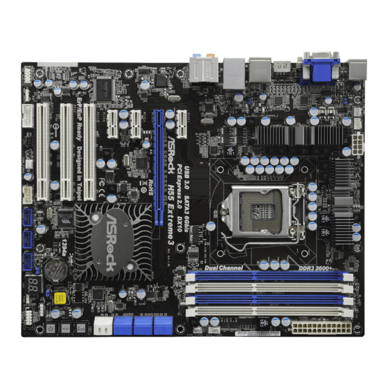
Page 2: Motherboard Layout
(HD_AUDIO1, White) SATA3 Connector (SATA3_1_2, White) PCI Slots (PCI1-3) Clear CMOS Switch (CLRCBTN) PCI Express 2.0 x1 Slot (PCIE4, White) Reset Switch (RSTBTN) PCI Express 2.0 x1 Slot (PCIE3, White) 64Mb SPI Flash PCI Express 2.0 x16 Slot (PCIE2, Blue) Power Switch (PWRBTN) PCI Express 2.0 x1 Slot (PCIE1, White) - Page 3 Line In (Light Blue) PS/2 Keyboard Port (Purple) ** 9 Front Speaker (Lime) * There are two LED next to the LAN port. Please refer to the table below for the LAN port LED indications. LAN Port LED Indications ACT/LINK...
- Page 4 To enable Multi-Streaming function, you need to connect a front panel audio cable to the front panel audio header. After restarting your computer, you will find “VIA HD Audio Deck” tool on your system. Please follow below instructions according to the OS you install.
-
Page 5: Package Contents
This Quick Installation Guide contains introduction of the motherboard and step-by- step installation guide. More detailed information of the motherboard can be found in the user manual presented in the Support CD. Because the motherboard specifications and the BIOS software might be updated, the content of this manual will be subject to change without notice. -
Page 6: Specifications
Specifications Specifications Specifications Specifications Specifications Platform - ATX Form Factor: 12.0-in x 9.6-in, 30.5 cm x 24.4 cm - All Solid Capacitor design (100% Japan-made high-quality Conductive Polymer Capacitors) ® ® - Supports Intel Core i7 / i5 / i3 and Pentium... - Page 7 NCQ, AHCI and “Hot Plug” functions (SATA3_2 connector is shared with eSATA3 port) USB 3.0 - 1 x USB3.0 port by Fresco FL1000G, supports USB 3.0 up to 5Gb/s Connector - 6 x SATAII 3.0Gb/s connectors, support NCQ, AHCI and “Hot Plug”...
- Page 8 - 3 x USB 2.0 headers (support 6 USB 2.0 ports) (see CAUTION 11) - 1 x Dr. Debug (7-Segment Debug LED) Smart Switch - 1 x Clear CMOS Switch with LED - 1 x Power Switch with LED - 1 x Reset Switch with LED...
- Page 9 Overclocking may affect your system stability, or even cause damage to the components and devices of your system. It should be done at your own risk and expense. We are not responsible for possible damage caused by overclocking.
- Page 10 USB flash drive or hard drive must use FAT32/16/12 file system. 15. The software name itself – OC DNA literally tells you what it is capable of. OC DNA, an exclusive utility developed by ASRock, provides a conve- nient way for the user to record the OC settings and share with others.
-
Page 11: Pre-Installation Precautions
Before you insert the 1156-Pin CPU into the socket, please check if the CPU surface is unclean or if there is any bent pin on the socket. Do not force to insert the CPU into the socket if above situation is found. - Page 12 100 degrees. Step 2. Remove PnP Cap (Pick and Place Cap). 1. It is recommended to use the cap tab to handle and avoid kicking off the PnP cap. 2. This cap must be placed if returning the motherboard for after service.
- Page 13 Installation of CPU Fan and Heatsink Installation of CPU Fan and Heatsink For proper installation, please kindly refer to the instruction manuals of your CPU fan and heatsink. Below is an example to illustrate the installation of the heatsink for 1156-Pin CPU.
-
Page 14: Installation Of Memory Modules (Dimm)
(the same brand, speed, size and chip- type) DDR3 DIMM pair in the slots of the same color. In other words, you have to install identical DDR3 DIMM pair in Dual Channel (DDR3_A1 and DDR3_B1;... -
Page 15: Installing A Dimm
Unlock a DIMM slot by pressing the retaining clips outward. Step 2. Align a DIMM on the slot such that the notch on the DIMM matches the break on the slot. The DIMM only fits in one correct orientation. It will cause permanent damage to the motherboard and the DIMM if you force the DIMM into the slot at incorrect orientation. -
Page 16: Expansion Slots (Pci And Pci Express Slots)
PCI slot is used to install expansion cards that have the 32-bit PCI interface. PCIE slots: PCIE1 / PCIE3 / PCIE4 (PCIE x1 slot; White) is used for PCI Express cards with x1 lane width cards, such as Gigabit LAN card, SATA2 card, etc. -
Page 17: Jumpers Setup
CLRCMOS1 for 5 seconds. However, please do not clear the CMOS right after you update the BIOS. If you need to clear the CMOS when you just finish updating the BIOS, you must boot up the system first, and then shut it down before you do the clear-CMOS action. -
Page 18: Onboard Headers And Connectors
If you clear the CMOS, the case open may be detected. Please adjust the BIOS option “Clear Status” to clear the record of previous chassis intrusion status. 2.6 Onboard Headers and Connectors 2.6 Onboard Headers and Connectors 2.6 Onboard Headers and Connectors 2.6 Onboard Headers and Connectors... - Page 19 HDA to function correctly. Please follow the instruction in our manual and chassis manual to install your system. 2. If you use AC’97 audio panel, please install it to the front panel audio header as below: A.
- Page 20 E. Enter BIOS Setup Utility. Enter Advanced Settings, and then select Chipset Configuration. Set the Front Panel Control option from [Auto] to [Enabled]. System Panel Header This header accommodates several system front panel (9-pin PANEL1) functions. (see p.2 No. 22)
- Page 21 Though this motherboard provides 4-Pin CPU fan (Quiet Fan) support, the 3-Pin CPU fan still can work successfully even without the fan speed control function. If you plan to connect the 3-Pin CPU fan to the CPU fan connector on this motherboard, please connect it to Pin 1-3.
- Page 22 HDMI_SPDIF Header HDMI_SPDIF header, providing SPDIF audio output to HDMI VGA (3-pin HDMI_SPDIF1) card, allows the system to (see p.2 No. 34) connect HDMI Digital TV/ projector/LCD devices. Please connect the HDMI_SPDIF connector of HDMI VGA card to this header.
-
Page 23: Smart Switches
CMOS values (see p.2 No. 16) You are not allowed to use Clear CMOS switch function if you set up the system password. If you want to clear the CMOS values, please clean your system password in advance or refer to page 17 “Clear CMOS jumper” description instead. - Page 24 Please see the diagrams below for reading the Dr. Debug codes. The Bootblock initialization code sets up the chipset, memory and other components before system memory is available. The following table describes the type of checkpoints that may occur during the bootblock initialization portion of the BIOS: Checkpoint...
- Page 25 Initializes the interrupt controlling hardware (generally PIC) and interrupt vector table. Do R/W test to CH-2 count reg. Initialize CH-0 as system timer. Install the POSTINT1Ch handler. Enable IRQ-0 in PIC for system timer interrupt. Traps INT1Ch vector to “POSTINT1ChHandlerBlock.”...
- Page 26 Initializes different devices through DIM. Initializes DMAC-1 & DMAC-2. Initialize RTC date/time. Test for total memory installed in the system. Also, Check for DEL or ESC keys to limit memory test. Display total memory in the system. Mid POST initialization of chipset registers.
-
Page 27: 64-Bit / Vista
Driver Installation Guide Driver Installation Guide To install the drivers to your system, please insert the support CD to your optical drive first. Then, the drivers compatible to your system can be auto-detected and listed on the support CD driver page. Please follow the order from up to bottom side to install those required drivers. -
Page 28: Untied Overclocking Technology
Untied Overclocking function, please enter “Overclock Mode” option of BIOS setup to set the selection from [Auto] to [Manual]. Therefore, CPU FSB is untied during overclocking, but PCI / PCIE buses are in the fixed mode so that FSB can operate under a more stable overclocking environment. -
Page 29: Bios Information
ROM drive. It will display the Main Menu automatically if “AUTORUN” is enabled in your computer. If the Main Menu does not appear automatically, locate and double- click on the file “ASSETUP.EXE” from the BIN folder in the Support CD to display the menus. - Page 30 Verpflichtung von ASRock zu Qualität und Halbarkeit. Diese Schnellinstallationsanleitung führt in das Motherboard und die schrittweise Installa- tion ein. Details über das Motherboard finden Sie in der Bedienungsanleitung auf der Support-CD. Da sich Motherboard-Spezifikationen und BIOS-Software verändern können, kann der Inhalt dieses Handbuches ebenfalls jederzeit geändert werden.
-
Page 31: Spezifikationen
Spezifikationen Spezifikationen Spezifikationen Spezifikationen Spezifikationen Plattform - ATX-Formfaktor: 30.5 cm x 24.4 cm; 12.0 Zoll x 9.6 Zoll - Alle Feste Kondensatordesign (100% in Japan gefertigte, erstklassige leitfähige Polymer-Kondensatoren) ® ® - Unterstützt Intel Core i7 / i5 / i3 und Pentium... - Page 32 - 5 x Standard-USB 2.0-Anschlüsse - 1 x eSATA3-Anschluss - 1 x Standard-USB 3.0-Anschlüsse - 1 x RJ-45 LAN Port mit LED (ACT/LINK LED und SPEED LED) - 1 x IEEE 1394 Port - HD Audiobuchse: Lautsprecher hinten / Mitte/Bass /...
- Page 33 - 1 x Netzschalter mit LED - 1 x Rücksetzschalter (Reset) mit LED BIOS - 64Mb AMI BIOS - AMI legal BIOS mit Unterstützung für “Plug and Play” - ACPI 1.1-Weckfunktionen - JumperFree-Übertaktungstechnologie - SMBIOS 2.3.1 - CPU VID, VCCM, SB, VTT, PCH PLL Stromspannung Multianpassung - Unterstützt I.
- Page 34 Beachten Sie bitte, dass Overclocking, einschließlich der Einstellung im BIOS, Anwenden der Untied Overclocking-Technologie oder Verwenden von Overclocking-Werkzeugen von Dritten, mit einem gewissen Risiko behaftet ist. Overclocking kann sich nachteilig auf die Stabilität Ihres Systems auswirken oder sogar Komponenten und Geräte Ihres Systems beschädigen.
- Page 35 Sie können nur die Nutzung von zwei von drei Bildschirmen auswählen. Die D-Sub-, DVI-D- und HDMI-Bildschirme können nicht gleichzeitig aktiviert werden. Zudem kann der DVI-D-Port mit DVI-zu-HDMI-Adapter dieselben Funktionen wie der HDMI-Port unterstützen. ® xvYCC und Deep Color werden nur unter Windows 7 64-Bit / 7 unterstützt.
- Page 36 15. Allein der Name – OC DNA* – beschreibt es wörtlich, was die Software zu leisten vermag. OC DNA ist ein von ASRock exklusiv entwickeltes Dienstprogramm, das Nutzern eine bequeme Möglichkeit bietet, Übertaktungseinstellungen aufzuzeichnen und sie Anderen mitzuteilen. Es hilft Ihnen, Ihre Übertaktungsaufzeichnung im Betriebssystem zu speichern und vereinfacht den komplizierten Aufzeichnungsvorgang von Übertaktungseinstellungen.
-
Page 37: Cpu Installation
Bevor Sie die 1156-Pin CPU in den Sockel sitzen, prüfen Sie bitte, ob die CPU-Oberfläche sauber ist und keine der Kontakte verbogen sind. Setzen Sie die CPU nicht mit Gewalt in den Sockel, dies kann die CPU schwer beschädigen. ASRock H55 Extreme3 Motherboard... - Page 38 Schritt 2. PnP-Kappe entfernen (Pick and Place-Kappe). 1. Verwenden Sie beim Entfernen die Kappenlasche und vermeiden Sie ein Abreißen der PnP-Kappe. 2. Diese Kappe muss angebracht werden, falls Sie das Motherboard zur Reparatur bringen. Schritt 3. 1156-Pin CPU einstecken: Schritt 3-1. Halten Sie die CPU an den mit schwarzen Linien gekennzeichneten Seiten.
- Page 39 Um die CPU ordnungsgemäß einsetzen zu können, richten Sie die zwei Orientierungskerben der CPU mit den beiden Markierungen des Sockels aus. Schritt 3-3. Drücken Sie die CPU vorsichtig in vertikaler Richtung in den Sockel. Schritt 3-4. Prüfen Sie, dass die CPU ordnungsgemäß...
- Page 40 Installation des CPU-Lüfters und Kühlkörpers Für Installationshinweise, siehe Betriebsanleitung Ihres CPU-Lüfters und Kühlkörpers. Unten stehend ein Beispiel zur Installation eines Kühlkörpers für den 1156-Pin CPU. (Tragen Sie Wärmeleitmaterial auf. ) Schritt 1. Geben Sie Wärmeleitmaterial auf die Mitte des IHS, auf die Sockeloberfläche.
- Page 41 Bestückt Bestückt Bestückt Bestückt * Für Konfiguration (2) installieren Sie bitte identische DDR3 DIMMs in allen vier Steckplätzen. 1. Wenn Sie zwei Speichermodule installieren möchten, verwenden Sie dazu für optimale Kompatibilität und Stabilität Steckplätze gleicher Farbe. Installieren Sie die beiden Speichermodule also entweder in den Weiß...
- Page 42 Öffnen Sie einen DIMM-Slot, indem Sie die seitlichen Clips nach außen drücken. Schritt 2: Richten Sie das DIMM-Modul so über dem Slot aus, dass das Modul mit der Kerbe in den Slot passt. Die DIMM-Module passen nur richtig herum eingelegt in die Steckplätze.
- Page 43 Gehäuseschacht (Slot) , den Sie nutzen möchten und behalten die Schraube für den Einbau der Karte. Schritt 3: Richten Sie die Karte über dem Slot aus und drücken Sie sie ohne Gewalt hinein, bis sie den Steckplatz korrekt ausfüllt. Schritt 4: Befestigen Sie die Karte mit der Schraube aus Schritt 2.
-
Page 44: Einstellung Der Jumper
+5VSB (Standby) zu setzen (siehe S.2 - No. 1) und die PS/2 oder USB01- Weckfunktionen zu aktivieren. Hinweis: Um +5VSB nutzen zu können, muss das Netzteil auf dieser Leitung 2A oder mehr leisten können. USB_PWR2 Überbrücken Sie Pin2, Pin3, um +5V_DUAL zu setzen und die (siehe S.2 - No. - Page 45 Werkseinstellung zurückzusetzen, schalten Sie bitte den Computer ab und entfernen das Stromkabel. Benutzen Sie eine Jumperkappe, um die Pin 2 und Pin 3 an CLRCMOS1 für 5 Sekunden kurzzuschließen. Bitte vergessen Sie nicht, den Jumper wieder zu entfernen, nachdem das CMOS gelöscht wurde.
- Page 46 2.6 Integrierte Header und Anschlüsse 2.6 Integrierte Header und Anschlüsse 2.6 Integrierte Header und Anschlüsse Integrierte Header und Anschlüsse sind KEINE Jumper. Setzen Sie KEINE Jumperkappen auf diese Header und Anschlüsse. Wenn Sie Jumperkappen auf Header und Anschlüsse setzen, wird das Motherboard unreparierbar beschädigt!
- Page 47 USB 2.0-Header Zusätzlich zu den fünf üblichen USB 2.0-Ports an den (9-pol. USB7_8) I/O-Anschlüssen befinden sich (siehe S.2 - No. 29) drei USB 2.0- Anschlussleisten am Motherboard. Pro USB 2.0- Anschlussleiste werden zwei (9-pol. USB9_10) USB 2.0-Ports unterstützt. (siehe S.2 - No. 28) (9-pol.
- Page 48 Geräte), wobei jedoch die Bildschirmverdrahtung am Gehäuse HDA unterstützen muss, um richtig zu funktionieren. Beachten Sie bei der Installation im System die Anweisungen in unserem Handbuch und im Gehäusehandbuch. 2. Wenn Sie die AC’97-Audioleiste verwenden, installieren Sie diese wie nachstehend beschrieben an der Front-Audioanschlussleiste: A.
- Page 49 Obwohl dieses Motherboard einen 24-pol. ATX-Stromanschluss bietet, kann es auch mit einem modifizierten traditionellen 20-pol. ATX-Netzteil verwendet werden. Um ein 20-pol. ATX-Netzteil zu verwenden, stecken Sie den Stecker mit Pin 1 und Pin 13 ein. Installation eines 20-pol. ATX-Netzteils ASRock H55 Extreme3 Motherboard...
- Page 50 (siehe S.2 - No. 4) Obwohl diese Hauptplatine 8-Pin ATX 12V Stromanschluss zur Verfügung stellt, kann sie noch arbeiten, wenn Sie einen traditionellen 4-Pin ATX 12V Energieversorgung adoptieren. Um die 4-Pin ATX Energieversorgung zu verwenden, stecken Sie bitte Ihre Energieversorgung zusammen mit dem Pin 1 und Pin 5 ein.
- Page 51 Ende (A) des (Option) HDMI_SPDIF-Kabels mit dem HDMI_SPDIF-Anschluss am Motherboard. Schließen Sie dann das weiße Ende (B oder C) des HDMI_SPDIF-Kabels an den HDMI_SPDIF-Anschluss der HDMI-VGA-Karte an. A. Schwarzes Ende B. Weißes Ende (zweipolig) C. Weißes Ende (dreipolig) ASRock H55 Extreme3 Motherboard...
- Page 52 Schnellschalter Schnellschalter Schnellschalter Schnellschalter Schnellschalter Dieses Motherboard besitzt drei Schnellschalter: Netzschalter, Rücksetzschalter (Reset) und CMOS löschen-Schalter, mit denen Benutzer das System schnell ein-/ ausschalten oder zurücksetzen oder die CMOS-Werte löschen können. Netzschalter Der Netzschalter ist ein Schnellschalter, mit dem (PWRBTN) Benutzer das System schnell (siehe S.2 - No.
-
Page 53: 64-Bit / Vista
Anschließend werden die mit Ihrem System kompatiblen Treiber automatisch erkannt und auf dem Bildschirm angezeigt. Zur Installation der nötigen Treiber gehen Sie bitte der Reihe nach von oben nach unten vor. Nur so können die von Ihnen installierten Treiber richtig arbeiten. - Page 54 7 / 7 64-Bit / Vista / Vista 64-Bit ohne RAID-Funktionalität auf Ihren SATA / SATAII-Festplatten installieren, gehen Sie bitte wie folgt vor. Verwendung von SATA / SATAII-Festplatten ohne NCQ-Funktionen SCHRITT 1: BIOS einrichten. A. Rufen Sie das BIOS SETUP UTILITY auf, wählen Sie den „Advanced“- Bildschirm (Erweitert), dann „Storage Configuration“.
- Page 55 Erscheint der Wilkommensbildschirm nicht, so “doppelklicken” Sie bitte auf das File ASSETUP.EXE im BIN-Verzeichnis der Support-CD, um die Menüs aufzurufen. Das Setup-Programm soll es Ihnen so leicht wie möglich machen. Es ist menügesteuert, d.h. Sie können in den verschiedenen Untermenüs Ihre Auswahl treffen und die Programme werden dann automatisch installiert.
-
Page 56: Contenu Du Paquet
1. Introduction 1. Introduction Merci pour votre achat d’une carte mère ASRock H55 Extreme3, une carte mère très fiable produite selon les critères de qualité rigoureux de ASRock. Elle offre des performances excellentes et une conception robuste conformément à l’engagement d’ASRock sur la qualité... -
Page 57: Spécifications
- Prend en charge le profil de mémoire extrême Intel (XMP) (voir ATTENTION 6) Slot d’extension - 1 x slot PCI Express 2.0 x16 (bleu @ mode x16) - 3 x slots PCI Express 2.0 x1 (2,5GT/s) - 3 x slots PCI VGA sur carte * * Requiert un processeur disposant de la technologie graphique ®... - Page 58 HBR (High Bit Rate Audio : Audio à haut débit binaire) avec HDMI 1.3a (Moniteur compatible HDMI requis) (voir ATTENTION 9) - Prise en charge de la fonction HDCP avec ports DVI et HDMI - Supporter 1080p Blu-ray(BD)/ lecteur de HD-DVD avec ports DVI et HDMI...
- Page 59 - br. 8 connecteur d’alimentation 12V ATX - Connecteur audio panneau avant - 3 x En-tête USB 2.0 (prendre en charge 6 ports USB 2.0 supplémentaires) (voir ATTENTION 11) - 1 x Dr. Debug (LED de débogage à 7 segments) Interrupteur - 1 x interrupteur d’effacement du CMOS avec LED...
- Page 60 - FCC, CE, WHQL - Prêt pour ErP/EuP (alimentation Prêt pour ErP/EuP requise) (voir ATTENTION 19) * Pour de plus amples informations sur les produits, s’il vous plaît visitez notre site web: http://www.asrock.com ATTENTION Il est important que vous réalisiez qu’il y a un certain risque à effectuer l’overclocking, y compris ajuster les réglages du BIOS, appliquer la technologie Untied Overclocking, ou...
- Page 61 Deep Color ne sont pris en charge que sous Windows 7 64-bit / 7. Le mode Deep Color ne sera activé que si le moniteur prend en charge ® 12bpc en EDID. HBR est pris en charge sous Windows...
- Page 62 Pour améliorer la dissipation de la chaleur, n’oubliez pas de mettre de la pâte thermique entre le CPU le dissipateur lors de l’installation du PC.
- Page 63 A chaque désinstallation de composant, placez-le sur un support antistatique ou dans son sachet d’origine. Lorsque vous placez les vis dans les orifices pour vis pour fixer la carte mère sur le châssis, ne serrez pas trop les vis ! Vous risquez sinon d’endommager la carte mère.
- Page 64 1. Il est recommandé d’utiliser la languette du capuchon ; évitez de faire sortir le capuchon PnP. 2. Ce capuchon doit être mis en place si vous renvoyez la carte mère pour service après vente. Etape 3. Insérez le processeur 1156 broches : Etape 3-1.
- Page 65 Pour une installation correcte, veuillez vous reporter aux manuels d’instructions de votre ventilateur de processeur et de votre dissipateur thermique. L’exemple ci-dessous illustre l’installation du dissipateur thermique pour un processeur 1366 broches.
- Page 66 Répétez l’opération avec les autres attaches. (Enfoncez (4 endroits)) Si vous enfoncez les attaches sans les faire tourner dans le sens des aiguilles d’une montre, le dissipateur thermique ne sera pas fixé sur la carte mère.
- Page 67 DIMM DDR3 identiques (de la même marque, de la même vitesse, de la même taille et du même type de puce) dans les slots de même couleur. En d’autres termes, vous devez installer une paire de DIMM DDR3 identiques dans le Canal Double (DDR3_A1 et DDR3_B1;...
- Page 68 Installation d’un module DIMM Installation d’un module DIMM Installation d’un module DIMM Ayez bien le soin de débrancher l’alimentation avant d’ajouter ou de retirer des modules DIMM ou les composants du système. Etape 1. Déverrouillez un connecteur DIMM en poussant les taquets de maintien vers l’extérieur.
-
Page 69: Installation D'une Carte D'extension
Slot d’extension (Slots PCI et Slots PCI Express) Slot d’extension (Slots PCI et Slots PCI Express) Il y a 3 ports PCI et 4 ports PCI Express sur la carte mère H55 Extreme3. Slots PCI: Les slots PCI sont utilisés pour installer des cartes d’extension dotées d’une interface PCI 32 bits. - Page 70 (voir p.2 No. 1) (standby) et permettre aux périphériques PS/2 ou USB01 de réveiller le système. Note: Pour sélectionner +5VSB, il faut obligatoirement 2 Amp et un courant standby supérieur fourni par l’alimentation. USB_PWR2 Court-circuitez les broches 2 et 3 pour choisir +5V_DUAL (voir p.2 No.
- Page 71 Toutefois, veuillez ne pas effacer la CMOS tout de suite après avoir mis le BIOS à jour. Si vous avez besoin d’effacer la CMOS lorsque vous avez fini de mettre le BIOS à jour, vous devez d’abord initialiser le système, puis le mettre hors tension avant de...
- Page 72 Les en-têtes et connecteurs sur carte NE SONT PAS des cavaliers. NE PAS placer les capuchons de cavalier sur ces en-têtes et connecteurs. Le fait de placer les capuchons de cavalier sur les en- têtes et connecteurs causera à la carte mère des dommages irréversibles!
- Page 73 En-tête USB 2.0 A côté des cinq ports USB 2.0 par défaut sur le (US7_8 br.9) panneau E/S, il y a trois (voir p.2 No. 29) embases USB 2.0 sur cette carte mère. Chaque embase USB 2.0 peut prendre en charge 2 ports USB 2.0.
- Page 74 1. L’audio à haute définition (HDA) prend en charge la détection de fiche, mais le fil de panneau sur le châssis doit prendre en charge le HDA pour fonctionner correctement. Veuillez suivre les instructions dans notre manuel et le manuel de châssis afin installer votre système.
- Page 75 (voir p.2 No. 3) ien que cette carte mère offre un support de (Ventilateur silencieux) ventilateur de CPU à 4 broches , le ventilateur de CPU à 3 broches peut bien fonctionner même sans la fonction de commande de vitesse du ventilateur.
- Page 76 (voir p.2 No. 4) Bien que cette carte mère possède 8 broches connecteur d’alimentation ATX 12V, il peut toujours travailler si vous adoptez une approche traditionnelle à 4 broches ATX 12V alimentation. Pour utiliser l’alimentation des 4 broches ATX, branchez votre alimentation avec la broche 1 et la broche 5.
- Page 77 Veuillez connecter l’extrémité noire (A) du câble HDMI_SPDIF (en option) au collecteur HDMI_SPDIF de la carte-mère. Connectez ensuite l’extrémité blanche (B ou C) du câble HDMI_SPDIF au connecteur HDMI_SPDIF de la carte VGA HDMI. A. extrémité noire B. extrémité blanche C.
- Page 78 (Effacement du CMOS) si vous configurez un mot de passe pour le système. Si vous voulez effacer les valeurs du CMOS, veuillez d’abord effacer le mot de passe de votre système ou vous référer plutôt à la description “Clear CMOS jumper (Cavalier d’effacement du CMOS)” de la page 71.
- Page 79 LED de débogage LED de débogage La LED de débogage intégrée sert à fournir des informations de code, ce qui rend le dépannage encore plus facile. Veuillez consulter les diagrammes des pages 24, 25 et 26 pour la lecture des codes LED de débogage.
- Page 80 7 / 7 64-bit / Vista / Vista 64-bit sur vos disques durs SATA / SATAII sans les fonctions RAID, veuillez suivre la procédure ci-dessous. Utilisation des disques durs SATA / SATAII sans NCQ fonctions ETAPE 1 : Configurez le BIOS.
-
Page 81: Informations Sur Le Cd De Support
BIOS après le POST, veuillez redémarrer le système en pressant <Ctl> + <Alt> + <Suppr>, ou en pressant le bouton de reset sur le boîtier du système. Vous pouvez également redémarrer en éteignant le système et en le rallumant. -
Page 82: Contenuto Della Confezione
Grazie per aver scelto una scheda madre ASRock H55 Extreme3, una scheda madre affidabile prodotta secondo i severi criteri di qualità ASRock. Le prestazioni eccellenti e il design robusto si conformano all’impegno di ASRock nella ricerca della qualità e della resistenza. - Page 83 1.2 Specifiche Specifiche Specifiche Specifiche Specifiche Piattaforma - ATX Form Factor: 12.0-in x 9.6-in, 30.5 cm x 24.4 cm - Design condensatore compatto (condensatori a conduttore in polimero di alta qualità realizzati al 100% in Giappone) ® ® Processore - Supporto dei processori Intel...
- Page 84 Premium Level HD Audio con protezioni contenuti - DAC con raggio dinamico di 110dB (VIA ® VT2020 Audio Codec) - Supporto audio HDMI con Dolby True HD e DTS HD Master Audio ® (quando sono installate CPU Intel Core i5 600 Series / i3 500 ®...
- Page 85 - 24-pin collettore alimentazione ATX - 8-pin connettore ATX 12V - Connettore audio sul pannello frontale - 3 x Collettore USB 2.0 (supporta 6 porte USB 2.0) (vedi ATTENZIONE 11) - 1 x Dr. Debug (LED debug con 7 segmenti)
- Page 86 * Per ulteriori informazioni, prego visitare il nostro sito internet: http://www.asrock.com AVVISO Si prega di prendere atto che la procedura di overclocking implica dei rischi, come anche la regolazione delle impostazioni del BIOS, l’applicazione della tecnologia Untied Overclocking Technology, oppure l’uso di strumenti di overclocking forniti da terzi. L’overclocking può...
- Page 87 (dischi floppy) o altre complicate utilità Flash. Si prega di notare che l’unità Flash USB o il disco rigido devono usare il File System FAT32/16/ 15. Il nome stesso del software – OC DNA – dice di cosa è capace. OC DNA, una utilità esclusiva sviluppata da ASRock, fornisce un modo comodo per registrare le impostazioni OC e condividerle con gli altri.
- Page 88 Intel l’alimentatore predisposto EuP deve soddisfare lo standard secondo cui l’efficienza energetica in standby di 5 v è più alta del 50% con un consumo di corrente di 100 mA. Per la scelta di un’alimentatore predisposto EuP consigliamo di verificare ulteriori dettagli con il produttore.
-
Page 89: Installazione
4. Ogni volta che si disinstalla un componente, appoggiarlo su un tappetino antistatico messo a terra o depositarlo nella borsa data in dotazione con il componente. 5. Nell’usare i giraviti per fissare la scheda madre al telaio non serrare eccessivamente le viti! Altrimenti si rischia di danneggiare la scheda madre. - Page 90 Fase 2. Rimuovere il cappuccio PnP (Pick and Place: prelievo e posizionamento). 1. Si raccomanda di utilizzare la linguetta del cappuccio per la manipolazione ed evitare di far saltare via il cappuccio PnP. 2. Questo tappo deve essere inserito se se la scheda madre deve essere restituita per l’assistenza.
- Page 91 Per il corretto inserimento, verificare di far combaciare i due denti di allineamento della CPU con le due tacche nel socket. Fase 3-3. Collocare con delicatezza la CPU sulla presa con un movimento puramente verticale. Fase 3-4. Verificare che la CPU sia all’interno...
- Page 92 Notare che questa scheda mare supporta l’opzione C.C.O. (Combo Cooler Option), che fornisce la flessibilità di impiegare due tipi diversi di dispersori di calore CPU, Socket LGA 775 e LGA 1156. I fori di colore bianco sono per la ventola CPU Socket LGA 1156.
- Page 93 2.3 Installazione dei moduli di memoria (DIMM) La scheda madre H55 Extreme3 fornisce quattro alloggiamenti DIMM DDR3 (Double Data Rate 3) a 240 pin, e supporta la tecnologia Dual Channel Memory. Per la configurazione a due canali, è necessario installare sempre coppie identiche (stessa marca, velocità, dimensioni e tipo di chip) di DIMM DDR3 negli alloggiamenti...
- Page 94 Sbloccare lo slot DIMM premendo i fermi che lo trattengono verso l’esterno. Step 2. Allineare una DIMM sullo slot così che il pettine della DIMM combaci con la sua sede sullo slot. La DIMM può essere montata correttamente soltanto con un orientamento.
- Page 95 Step 2. Rimuovere i ganci sullo slot che si intende utilizzare. Tenere a portata di mano le viti. Step 3. Allineare il connettore della scheda con lo slot e premere con decisione finché...
- Page 96 +5VSB (standby) e (vedi p.2 Nr. 1) abilitare PS/2 o USB01 wake up events. Nota: Per selezionare +5VSB, si richiedono almeno 2 Ampere e il consumo di corrente in standby sarà maggiore. USB_PWR2 Cortocircuitare pin2, pin3 per settare a +5V_DUAL e abilitare (vedi p.2 Nr.
- Page 97 Azzeramento predefinita CMOS Nota: CLRCMOS1 permette di cancellare i dati presenti nel CMOS. I dati del CMOS comprendono le informazioni di configurazione quali la password di sistema, data, ora, e i parametri di configurazione del sistema. Per cancellare e ripristinare i parametri del sistema, spegnere il computer e togliere il cavo di alimentazione dalla presa di corrente.
- Page 98 2.6 Collettori e Connettori su Scheda 2.6 Collettori e Connettori su Scheda I collettori ed i connettori su scheda NON sono dei jumper. NON installare cappucci per jumper su questi collettori e connettori. L’installazione di cappucci per jumper su questi collettori e connettori provocherà danni...
- Page 99 Collettore USB 2.0 Oltre alle cinque porte USB 2.0 predefinite nel pannello I/O, la (9-pin USB7_8) scheda madre dispone di (vedi p.2 Nr. 29) tre intestazioni USB 2.0. Ciascuna intestazione USB 2.0 supporta due porte USB 2.0. (9-pin USB9_10) (vedi p.2 Nr. 28) (9-pin USB11_12) (vedi p.2 Nr.
- Page 100 1. La caratteristica HDA (High Definition Audio) supporta il rilevamento dei connettori, però il pannello dei cavi sul telaio deve supportare la funzione HDA (High Definition Audio) per far sì che questa operi in modo corretto. Attenersi alle istruzioni del nostro manuale e del manuale del telaio per installare il sistema.
- Page 101 Sebbene la presente scheda madre disponga di un supporto per ventola CPU a 4 piedini (ventola silenziosa), la ventola CPU a 3 piedini è in grado di funzionare anche senza la funzione di controllo della velocità della ventola. Se si intende collegare la ventola CPU a 3 piedini al connettore della ventola CPU su questa scheda madre, collegarla ai piedini 1-3.
- Page 102 Sebbene questa schedamadre fornisca un connettore elettrico 8-pin ATX 12V, l‘unita‘ puo‘ ancora essere funzionante se viene utilizzata una fornitura elettrica tradizionale a 4-pin ATX 12V. Per usare tale fornitura elettrica 4-pin ATX 12V, prego collegare la presa elettrica al Pin 1 e Pin 5.
- Page 103 Interruttori rapidi Interruttori rapidi Questa scheda madre ha tre interruttori rapidi: Interruttore di alimentazione, interruttore di reset e interruttore pulizia CMOS, che consentono agli utenti di accendere / spegnere rapidamente o cancellare i valori CMOS. Interruttore L’interruttore di alimentazione è...
- Page 104 Quindi, i driver compatibili con il sistema vengono rilevati automaticamente ed elencati nella pagina del driver del CD in dotazione. Per l’installazione dei driver necessari, procedere in base ad un ordine dall’alto verso il basso. In tal modo, i driver installati funzioneranno correttamente.
- Page 105 7 / 7 64-bit / Vista / Vista 64-bit sulle unità disco rigido SATA / SATAII senza funzioni RAID, seguire le istruzioni esposte di seguito. Utilizzo dei dischi rigidi SATA / SATAII privi di funzioni NCQ Passo 1: Configurare il BIOS.
- Page 106 BIOS; altrimenti, POST continua con i suoi test di routine. Per entrare il BIOS Setup dopo il POST, riavvia il sistema premendo <Ctl> + <Alt> + <Delete>, o premi il tasto di reset sullo chassis del sistema. Per informazioni più dettagliate circa il Setup del BIOS, fare riferimento al Manuale dell’Utente (PDF file) contenuto nel cd di...
-
Page 107: Contenido De La Caja
ASRock. Esta Guía rápida de instalación contiene una introducción a la placa base y una guía de instalación paso a paso. Puede encontrar una información más detallada sobre la placa base en el manual de usuario incluido en el CD de soporte. - Page 108 - Admite D-Sub con una resolución máxima de 2048x1536 a 75 Hz - Admite Sincronización automática entre audio y vídeo, Deep Color (12 bpc), xvYCC y HBR (audio de alta tasa de bits) con HDMI 1.3a (se necesita un monitor compatible con HDMI) (ver ATENCIÓN 9) - Admite la función HDCP con puertos DVI y HDMI...
- Page 109 - 7.1 CH HD Audio con Protección de Contenido ® - DAC con rango dinámico de 110dB (VIA VT2020 Audio Codec) - Admite audio HDMI con Dolby True HD y Audio maestro DTS HD ® (cuando se instala un procesador Intel Core de la serie i5 ®...
- Page 110 - 8-pin conector de ATX 12V power - Conector de audio de panel frontal - 3 x Cabezal USB 2.0 (admite 6 puertos USB 2.0 adicionales) (vea ATENCIÓN 11) - 1 x Dr. Debug (indicador LED de avería de 7 segmentos)
- Page 111 ADVERTENCIA Tenga en cuenta que hay un cierto riesgo implícito en las operaciones de aumento de la velocidad del reloj, incluido el ajuste del BIOS, aplicando la tecnología de aumento de velocidad liberada o utilizando las herramientas de aumento de velocidad de otros fabricantes.
- Page 112 ASRock Instant Flash. Ejecute esta herramienta y guarde el archivo correspondiente al sistema BIOS nuevo en su unidad flash USB, unidad de disco flexible o disco duro para poder actualizar el BIOS con sólo pulsar un par de botones, sin necesidad de preparar un disco flexible adicional ni utilizar complicadas utilidades de programación.
- Page 113 15. El nombre del propio software, OC DNA, indica con claridad aquello de lo que es capaz. OC DNA, una exclusiva utilidad desarrollada por ASRock, representa para el usuario una forma cómoda de grabar su configuración de OC y compartirla con otras personas. Esta utilidad le permitirá guardar sus registros de aceleración en el sistema operativo y simplificar el...
-
Page 114: Instalación
4. Ponga cualquier componente deslocalizado sobre la bolsa anti- estástica que viene con la placa madre. 5. Al colocar los tornillos en sus agujeros para fijar la placa madre en el chasis, no los apriete demasiado. Eso podría dañar la placa madre. - Page 115 Paso 2. Retire la cubierta PnP (Pick and Place). 1. Se recomienda que utilice la lengüeta de la cubierta para retirarla, evitando arrancar la cubierta PnP. 2. Esta cobertura debe colocarse si la placa base vuelve tras ser reparada. Paso 3. Inserte la CPU de 1156 agujas: Paso 3-1.
- Page 116 Para una correcta instalación, consulte los manuales de instrucciones del ventilador y el disipador de la CPU. A continuación se ofrece un ejemplo para ilustrar la instalación del disipador para la CPU de 1156 agujas. Paso 1. Aplique el material termal de interfaz en el (Aplique el material termal de interfaz) centro del IHS de la superficie del socket.
- Page 117 Repita el proceso con los cierres restantes. (Pulse (4 lugares)) Si presiona los cierres sin girarlos en el sentido de las agujas del reloj, el disipador no se podrá fijar a la placa madre. Paso 5. Conecte el cabezal del ventilador con el conector del ventilador de la CPU en la placa madre.
-
Page 118: Instalación De Memoria
Tecnología de Memoria de Doble Canal. Para la configuración de doble canal, necesitará instalar siempre pares DIMM DDR3 idénticos (de la misma marca, velocidad, tamaño y tipo) en las ranuras del mismo color. En otras palabras, tendrá que instalar pares pares idénticos DDR3 DIMM en el Doble Canal (DDR3_A1 y DDR3_B1;... - Page 119 Asegúrese de desconectar la fuente de alimentación antes de añadir o retirar módulos DIMM o componentes del sistema. Paso 1. Empuje los clips blancos de retención por el extremo de cada lado de la ranura de memoria. Paso 2. Encaje la muesca del DIMM hacia la cumbrera de la ranura.
- Page 120 Paso 2. Quite la tapa que corresponde a la ranura que desea utilizar. Paso 3. Encaje el conector de la tarjeta a la ranura. Empuje firmemente la tarjeta en la ranura. Paso 4. Asegure la tarjeta con tornillos.
- Page 121 3 para habilitar +5VSB (vea p.2, N. 1) (standby) para PS/2 o USB01 wake up events. Atención: Para elegir +5VSB, se necesita corriente mas que 2 Amp proveida por la fuente de electricidad. USB_PWR2 Ponga en cortocircuito pin 2, pin 3 para habilitar +5V_DUAL (vea p.2, N.
- Page 122 Valor predeterminado Restablecimiento de la CMOS Atención: CLRCMOS1 permite que Usted limpie los datos en CMOS. Los datos en CMOS incluyen informaciones de la configuración del sistema, tales como la contraseña del sistema, fecha, tiempo, y parámetros de la configuración del sistema.
- Page 123 2.6 Cabezales y Conectores en Placas 2.6 Cabezales y Conectores en Placas Los conectores y cabezales en placa NO son puentes. NO coloque las cubiertas de los puentes sobre estos cabezales y conectores. El colocar cubiertas de puentes sobre los conectores y cabezales provocará un daño permanente en la placa base.
- Page 124 (5-pin IR1) transmisión y recepción (vea p.2, N. 32) wireless opcional. Conector de detección de intrusión en el chasis Esta placa base admite la función de control de (2-pin CI1) APERTURA DE CARCASA, que (vea p.2, N. 20) permite detectar si se ha retirado la cubierta del chasis.
- Page 125 2. Si utiliza el panel de sonido AC’97, instálelo en la cabecera de sonido del panel frontal de la siguiente manera: A. Conecte Mic_IN (MIC) a MIC2_L.
- Page 126 Si pretende enchufar el ventilador de procesador de 3 contactos en el conector del ventilador de procesador de esta placa base, conéctelo al contacto 1-3. Contacto 1-3 conectado Instalación del ventilador de 3 contactos...
- Page 127 Aunque esta placa base proporciona un conector de energía de 8-pin ATX 12V, puede todavía trabajar si usted adopta un fuente tradicional de energía de 4-pin ATX 12V. Para usar el fuente de energía de 4-pin ATX 12V, por favor conecte su fuente de energía junto con Pin 1 y Pin 5.
- Page 128 Esta placa base dispone de tres conmutadores rápidos: conmutador de encendido, conmutador de reinicio y conmutador de borrado de memoria CMOS. Dichos conmutadores permiten al usuario encender / apagar o reiniciar el sistema, o bien borrar el contenido de la memoria CMOS.
- Page 129 El indicador LED de depuración instalado en la placa se utiliza para presentar información en forma de códigos que facilitan la resolución de problemas. Consulte los diagramas de las páginas 24, 25 y 26 si desea obtener más información acerca de la lectura de los códigos del indicador LED de depuración.
- Page 130 7 / 7 64 bits / Vista / Vista 64 bits en sus discos duros SATA / SATAII sin funciones RAID, por favor siga los pasos siguientes. Uso de dispositivos SATA / SATAII sin funciones NCQ PASO 1: Configuración de la BIOS.
- Page 131 Para iniciar la instalación, ponga el CD en el lector de CD y se desplegará el Menú Principal automáticamente si «AUTORUN» está habilitado en su computadora.
- Page 132 1 5 5 1 5 5 1 5 5 1 5 5 1 5 5 ASRock H55 Extreme3 Motherboard...
- Page 133 ® ® ® ® ® ® ® ® 1 5 6 1 5 6 1 5 6 1 5 6 1 5 6 ASRock H55 Extreme3 Motherboard...
- Page 134 ® ® “ ” 1 5 7 1 5 7 1 5 7 1 5 7 1 5 7 ASRock H55 Extreme3 Motherboard...
- Page 135 ® ® 1 5 8 1 5 8 1 5 8 1 5 8 1 5 8 ASRock H55 Extreme3 Motherboard...
- Page 136 ® ® ® “ ” ® ® ® ® ® ® 1 5 9 1 5 9 1 5 9 1 5 9 1 5 9 ASRock H55 Extreme3 Motherboard...
- Page 137 ® 1 6 0 1 6 0 1 6 0 1 6 0 1 6 0 ASRock H55 Extreme3 Motherboard...
- Page 138 1 6 1 1 6 1 1 6 1 1 6 1 1 6 1 ASRock H55 Extreme3 Motherboard...
- Page 139 Pin1 Pin1 1 6 2 1 6 2 1 6 2 1 6 2 1 6 2 ASRock H55 Extreme3 Motherboard...
- Page 140 1 6 3 1 6 3 1 6 3 1 6 3 1 6 3 ASRock H55 Extreme3 Motherboard...
- Page 141 1 6 4 1 6 4 1 6 4 1 6 4 1 6 4 ASRock H55 Extreme3 Motherboard...
- Page 142 1 6 5 1 6 5 1 6 5 1 6 5 1 6 5 ASRock H55 Extreme3 Motherboard...
- Page 143 1 6 6 1 6 6 1 6 6 1 6 6 1 6 6 ASRock H55 Extreme3 Motherboard...
- Page 144 “ ” “ ” “ ” “ ” “ ” ” ” “ ” 1 6 7 1 6 7 1 6 7 1 6 7 1 6 7 ASRock H55 Extreme3 Motherboard...
- Page 145 1 6 8 1 6 8 1 6 8 1 6 8 1 6 8 ASRock H55 Extreme3 Motherboard...
- Page 146 1 6 9 1 6 9 1 6 9 1 6 9 1 6 9 ASRock H55 Extreme3 Motherboard...
- Page 147 1 7 0 1 7 0 1 7 0 1 7 0 1 7 0 ASRock H55 Extreme3 Motherboard...
- Page 148 4 3 2 1 1 7 1 1 7 1 1 7 1 1 7 1 1 7 1 ASRock H55 Extreme3 Motherboard...
- Page 149 1 7 2 1 7 2 1 7 2 1 7 2 1 7 2 ASRock H55 Extreme3 Motherboard...
- Page 150 RESET CMOS “ ” 1 7 3 1 7 3 1 7 3 1 7 3 1 7 3 ASRock H55 Extreme3 Motherboard...
- Page 151 ® ® ® ® ® ® 1 7 4 1 7 4 1 7 4 1 7 4 1 7 4 ASRock H55 Extreme3 Motherboard...
- Page 152 ® ® ® ® 1 7 5 1 7 5 1 7 5 1 7 5 1 7 5 ASRock H55 Extreme3 Motherboard...
- Page 153 “ ” “ ” 1 7 6 1 7 6 1 7 6 1 7 6 1 7 6 ASRock H55 Extreme3 Motherboard...
- Page 154 1 7 7 1 7 7 1 7 7 1 7 7 1 7 7 ASRock H55 Extreme3 Motherboard...
- Page 155 ® ® ® ® ® ® ® 1 7 8 1 7 8 1 7 8 1 7 8 1 7 8 ASRock H55 Extreme3 Motherboard...
- Page 156 ® ® ® 1 7 9 1 7 9 1 7 9 1 7 9 1 7 9 ASRock H55 Extreme3 Motherboard...
- Page 157 ® 1 8 0 1 8 0 1 8 0 1 8 0 1 8 0 ASRock H55 Extreme3 Motherboard...
- Page 158 ® ® ® ® ® ® “ ” ® ® ® ® ® 1 8 1 1 8 1 1 8 1 1 8 1 1 8 1 ASRock H55 Extreme3 Motherboard...
- Page 159 ® ® ® ® – 1 8 2 1 8 2 1 8 2 1 8 2 1 8 2 ASRock H55 Extreme3 Motherboard...
- Page 160 1 8 3 1 8 3 1 8 3 1 8 3 1 8 3 ASRock H55 Extreme3 Motherboard...
- Page 161 1 8 4 1 8 4 1 8 4 1 8 4 1 8 4 ASRock H55 Extreme3 Motherboard...
- Page 162 1 8 5 1 8 5 1 8 5 1 8 5 1 8 5 ASRock H55 Extreme3 Motherboard...
- Page 163 1 8 6 1 8 6 1 8 6 1 8 6 1 8 6 ASRock H55 Extreme3 Motherboard...
- Page 164 1 8 7 1 8 7 1 8 7 1 8 7 1 8 7 ASRock H55 Extreme3 Motherboard...
- Page 165 1 8 8 1 8 8 1 8 8 1 8 8 1 8 8 ASRock H55 Extreme3 Motherboard...
- Page 166 1 8 9 1 8 9 1 8 9 1 8 9 1 8 9 ASRock H55 Extreme3 Motherboard...
- Page 167 1 9 0 1 9 0 1 9 0 1 9 0 1 9 0 ASRock H55 Extreme3 Motherboard...
- Page 168 1 9 1 1 9 1 1 9 1 1 9 1 1 9 1 ASRock H55 Extreme3 Motherboard...
- Page 169 1 9 2 1 9 2 1 9 2 1 9 2 1 9 2 ASRock H55 Extreme3 Motherboard...
- Page 170 1 9 3 1 9 3 1 9 3 1 9 3 1 9 3 ASRock H55 Extreme3 Motherboard...
- Page 171 4 3 2 1 1 9 4 1 9 4 1 9 4 1 9 4 1 9 4 ASRock H55 Extreme3 Motherboard...
- Page 172 1 9 5 1 9 5 1 9 5 1 9 5 1 9 5 ASRock H55 Extreme3 Motherboard...
- Page 173 RESET CMOS 1 9 6 1 9 6 1 9 6 1 9 6 1 9 6 ASRock H55 Extreme3 Motherboard...
- Page 174 ® ® ® ® ® ® ® ® ® 1 9 7 1 9 7 1 9 7 1 9 7 1 9 7 ASRock H55 Extreme3 Motherboard...
- Page 175 ® 1 9 8 1 9 8 1 9 8 1 9 8 1 9 8 ASRock H55 Extreme3 Motherboard...
- Page 176 ® ® 1 9 9 1 9 9 1 9 9 1 9 9 1 9 9 ASRock H55 Extreme3 Motherboard...
- Page 177 2 0 0 2 0 0 2 0 0 2 0 0 2 0 0 ASRock H55 Extreme3 Motherboard...
- Page 178 ® ® ® ® ® ® ® ® 2 0 1 2 0 1 2 0 1 2 0 1 2 0 1 ASRock H55 Extreme3 Motherboard...
- Page 179 ® ® 2 0 2 2 0 2 2 0 2 2 0 2 2 0 2 ASRock H55 Extreme3 Motherboard...
- Page 180 ® ® ® 2 0 3 2 0 3 2 0 3 2 0 3 2 0 3 ASRock H55 Extreme3 Motherboard...
- Page 181 ® ® ® ® ® ® ® ® ® ® 2 0 4 2 0 4 2 0 4 2 0 4 2 0 4 ASRock H55 Extreme3 Motherboard...
- Page 182 ® ® 2 0 5 2 0 5 2 0 5 2 0 5 2 0 5 ASRock H55 Extreme3 Motherboard...
- Page 183 2 0 6 2 0 6 2 0 6 2 0 6 2 0 6 ASRock H55 Extreme3 Motherboard...
- Page 184 2 0 7 2 0 7 2 0 7 2 0 7 2 0 7 ASRock H55 Extreme3 Motherboard...
- Page 185 2 0 8 2 0 8 2 0 8 2 0 8 2 0 8 ASRock H55 Extreme3 Motherboard...
- Page 186 2 0 9 2 0 9 2 0 9 2 0 9 2 0 9 ASRock H55 Extreme3 Motherboard...
- Page 187 2 1 0 2 1 0 2 1 0 2 1 0 2 1 0 ASRock H55 Extreme3 Motherboard...
- Page 188 2 1 1 2 1 1 2 1 1 2 1 1 2 1 1 ASRock H55 Extreme3 Motherboard...
- Page 189 2 1 2 2 1 2 2 1 2 2 1 2 2 1 2 ASRock H55 Extreme3 Motherboard...
- Page 190 2 1 3 2 1 3 2 1 3 2 1 3 2 1 3 ASRock H55 Extreme3 Motherboard...
- Page 191 2 1 4 2 1 4 2 1 4 2 1 4 2 1 4 ASRock H55 Extreme3 Motherboard...
- Page 192 4 3 2 1 2 1 5 2 1 5 2 1 5 2 1 5 2 1 5 ASRock H55 Extreme3 Motherboard...
- Page 193 2 1 6 2 1 6 2 1 6 2 1 6 2 1 6 ASRock H55 Extreme3 Motherboard...
- Page 194 RESET CMOS 2 1 7 2 1 7 2 1 7 2 1 7 2 1 7 ASRock H55 Extreme3 Motherboard...
- Page 195 ® ® ® ® ® ® 2 1 8 2 1 8 2 1 8 2 1 8 2 1 8 ASRock H55 Extreme3 Motherboard...
- Page 196 ® ® ® ® 2 1 9 2 1 9 2 1 9 2 1 9 2 1 9 ASRock H55 Extreme3 Motherboard...
- Page 197 ® ® 2 2 0 2 2 0 2 2 0 2 2 0 2 2 0 ASRock H55 Extreme3 Motherboard...
- Page 198 2 2 1 2 2 1 2 2 1 2 2 1 2 2 1 ASRock H55 Extreme3 Motherboard...
- Page 199 2 2 2 2 2 2 2 2 2 2 2 2 2 2 2 ASRock H55 Extreme3 Motherboard...
- Page 200 ® ® ® ® ® ® ® ® 2 2 3 2 2 3 2 2 3 2 2 3 2 2 3 ASRock H55 Extreme3 Motherboard...
- Page 201 ® ® 2 2 4 2 2 4 2 2 4 2 2 4 2 2 4 ASRock H55 Extreme3 Motherboard...
- Page 202 ® ® ® 2 2 5 2 2 5 2 2 5 2 2 5 2 2 5 ASRock H55 Extreme3 Motherboard...
- Page 203 ® ® ® ® ® ® ® ® ® ® 2 2 6 2 2 6 2 2 6 2 2 6 2 2 6 ASRock H55 Extreme3 Motherboard...
- Page 204 ® ® 2 2 7 2 2 7 2 2 7 2 2 7 2 2 7 ASRock H55 Extreme3 Motherboard...
- Page 205 2 2 8 2 2 8 2 2 8 2 2 8 2 2 8 ASRock H55 Extreme3 Motherboard...
- Page 206 2 2 9 2 2 9 2 2 9 2 2 9 2 2 9 ASRock H55 Extreme3 Motherboard...
- Page 207 2 3 0 2 3 0 2 3 0 2 3 0 2 3 0 ASRock H55 Extreme3 Motherboard...
- Page 208 2 3 1 2 3 1 2 3 1 2 3 1 2 3 1 ASRock H55 Extreme3 Motherboard...
- Page 209 2 3 2 2 3 2 2 3 2 2 3 2 2 3 2 ASRock H55 Extreme3 Motherboard...
- Page 210 2 3 3 2 3 3 2 3 3 2 3 3 2 3 3 ASRock H55 Extreme3 Motherboard...
- Page 211 2 3 4 2 3 4 2 3 4 2 3 4 2 3 4 ASRock H55 Extreme3 Motherboard...
- Page 212 2 3 5 2 3 5 2 3 5 2 3 5 2 3 5 ASRock H55 Extreme3 Motherboard...
- Page 213 2 3 6 2 3 6 2 3 6 2 3 6 2 3 6 ASRock H55 Extreme3 Motherboard...
- Page 214 4 3 2 1 2 3 7 2 3 7 2 3 7 2 3 7 2 3 7 ASRock H55 Extreme3 Motherboard...
- Page 215 2 3 8 2 3 8 2 3 8 2 3 8 2 3 8 ASRock H55 Extreme3 Motherboard...
- Page 216 2 3 9 2 3 9 2 3 9 2 3 9 2 3 9 ASRock H55 Extreme3 Motherboard...
- Page 217 RESET CMOS 2 4 0 2 4 0 2 4 0 2 4 0 2 4 0 ASRock H55 Extreme3 Motherboard...
- Page 218 ® ® ® ® ® ® ® ® ® 2 4 1 2 4 1 2 4 1 2 4 1 2 4 1 ASRock H55 Extreme3 Motherboard...
- Page 219 ® 2 4 2 2 4 2 2 4 2 2 4 2 2 4 2 ASRock H55 Extreme3 Motherboard...
- Page 220 ® ® ® 2 4 3 2 4 3 2 4 3 2 4 3 2 4 3 ASRock H55 Extreme3 Motherboard...
Need help?
Do you have a question about the H55 EXTREME3 and is the answer not in the manual?
Questions and answers