Table of Contents
Advertisement
Quick Links
Advertisement
Table of Contents

Related Manuals for Siemens SINAMICS SDI Pro


Summary of Contents for Siemens SINAMICS SDI Pro
- Page 3 SINAMICS Smart Drive Interface SDI Pro 5.5'' Introduction Fundamental safety instructions SINAMICS Description Mounting SINAMICS Smart Drive Interface Connecting SDI Pro 5.5'' Initial setup of the Operator Panel Operating Instructions Functions and menus of the Operator Panel Using the Operator Panel with a converter Technical data Valid for firmware version 1.0...
- Page 4 Note the following: WARNING Siemens products may only be used for the applications described in the catalog and in the relevant technical documentation. If products and components from other manufacturers are used, these must be recommended or approved by Siemens. Proper transport, storage, installation, assembly, commissioning, operation and maintenance are required to ensure that the products operate safely and without any problems.
-
Page 5: Table Of Contents
SINAMICS SDI Pro 5.5'' Handheld Kit ................... 19 3.3.1.1 Overview ........................... 19 3.3.1.2 Technical data ........................20 3.3.2 SINAMICS SDI Pro 5.5'' Door Mounting Kit ................21 3.3.2.1 Overview ........................... 21 3.3.2.2 Installing the Operator Panel using the Door Mounting Kit ..........22 3.3.2.3 Technical data ........................ - Page 6 Table of contents Mounting ............................. 31 Dimensions ........................31 Mounting with the Handheld Kit ..................31 Mounting with the Door Mounting Kit ................32 Mounting with the Mounting frame ................... 32 Connecting ............................33 Interface overview ......................33 Maximum permissible cable lengths ................... 34 Connecting the Operator Panel to a converter ..............
- Page 7 Table of contents Diagnostics menu ......................96 8.4.1 Messages ........................... 96 8.4.2 Diagnostics buffer ......................97 8.4.3 Safety Integrated ....................... 98 8.4.4 Connection view ......................100 8.4.5 Communication ....................... 101 8.4.6 Control/status word ......................102 Parameter menu ......................103 8.5.1 Parameter list ........................
- Page 8 Table of contents SINAMICS Smart Drive Interface SDI Pro 5.5'' Operating Instructions, 03/2024, FW V1.0, A5E52612203B AA...
-
Page 9: Introduction
With the SINAMICS converter series you can solve drive tasks in the low, medium and DC voltage range. All Siemens drive components, such as converters, motors, and controls, are matched to each other and can be integrated into your existing automation systems. -
Page 10: Target Group
This document may contain hyperlinks to third-party websites. Siemens is not responsible for and shall not be liable for these websites and their content. Siemens has no control over the information which appears on these websites and is not responsible for the content and information provided there. -
Page 11: Sinamics Documentation
1.3 SINAMICS documentation SINAMICS documentation Description The documentation on the SINAMICS family of converters is available under Siemens Industry Online Support (https://support.industry.siemens.com/cs/ww/en/view/109807358). You can display documents or download them in PDF and HTML5 format. The Operator Panel documentation essentially comprises the following manuals:... -
Page 12: Spare Parts Services
QR code with ID link included The ID link is characterized by a frame with a black corner at the bottom right. Content of Siemens Online Support • Product support • Global forum for information and best practice sharing between users and specialists •... -
Page 13: Important Product Information
Introduction 1.5 Important product information Important product information 1.5.1 Intended use Requirement DANGER Ensuring a safe and stable state During commissioning of the converter it is essential to ensure that the system is in a safe and stable state, as some commissioning processes have the potential to start the motor. Therefore, it is important to secure any loads and ensure that should the motor start, no potentially dangerous conditions exist. - Page 14 Introduction 1.5 Important product information NOTICE Damage to the USB-C port due to potential power surges When you connect the converter-connected Operator Panel to the PC, power surges can occur and damage the USB-C port. • Before connecting the Operator Panel to a PC through the USB-C port, disconnect the Operator Panel from the converter.
-
Page 15: Firmware Updates And Constraints
1.5.4 Compliance with the General Data Protection Regulation Description Siemens complies with the principles of the General Data Protection Regulation (EU), in particular the principle of data minimization ("privacy by design"). For this SINAMICS product, this means: • User management and access control (UMAC) The product processes or stores the following personal data: –... - Page 16 Introduction 1.5 Important product information This data is used for user management and access control (UMAC) and for the support function. The storage of this data is appropriate and limited to what is necessary, as it is essential to identify the authorized operators and service contact. The personal data is also available as part of the backup system to ensure fast recovery of use cases.
-
Page 17: Fundamental Safety Instructions
Fundamental safety instructions General safety instructions WARNING Danger to life if the safety instructions and residual risks are not observed If the safety instructions and residual risks in the associated hardware documentation are not observed, accidents involving severe injuries or death can occur. •... -
Page 18: Cybersecurity Information
Siemens’ products and solutions undergo continuous development to make them more secure. Siemens strongly recommends that product updates are applied as soon as they are available and that the latest product versions are used. Use of product versions that are no longer supported, and failure to apply the latest updates may increase customer’s exposure to... -
Page 19: Description
Description SINAMICS SDI Pro 5.5'' Operator Panel Overview The SINAMICS SDI Pro 5.5'' Operator Panel (referred to as "Operator Panel") is a client device that allows you to access the web server integrated in the compatible SINAMICS converter. Description The Operator Panel is intended for use with the following SINAMICS converters: •... -
Page 20: Scope Of Delivery
Scope of delivery Description The delivery includes at least the following components: • A SINAMICS SDI Pro 5.5'' Operator Panel with loaded firmware (article number: 6SL4950- 0AH35-2AA0) • A connector for external 24 V DC power supply • A "Safety instructions" sheet SINAMICS Smart Drive Interface SDI Pro 5.5''... -
Page 21: Optional Components
Overview Description The optional SINAMICS SDI Pro 5.5'' Handheld Kit (referred to as the "Handheld Kit") allows the Operator Panel to be used in an easier and more comfortable manner. The Handheld Kit consists of a rubber housing, a plastic support, three magnetic pads located on the back of the Handheld Kit, and a 3 m Ethernet cable. -
Page 22: Technical Data
Description 3.3 Optional components Figure 3-2 Operator Panel with the Handheld Kit 3.3.1.2 Technical data Technical data of the Handheld Kit Table 3- 2 Technical data of the Handheld Kit Property Specification Weight including the supplied accessories 389 g Transport and storage ambient temperature -40 °C ... -
Page 23: Sinamics Sdi Pro 5.5'' Door Mounting Kit
Overview Description The optional SINAMICS SDI Pro 5.5'' Door Mounting Kit (referred to as the "Door Mounting Kit") enables the convenient installation of the Operator Panel onto a cabinet door, eliminating the need to open the door for visibility. The Door Mounting Kit consists of a back plate and 8 screws. -
Page 24: Installing The Operator Panel Using The Door Mounting Kit
Description 3.3 Optional components 3.3.2.2 Installing the Operator Panel using the Door Mounting Kit Procedure Proceed as follows to install the Operator Panel on the cabinet door by using the Door Mounting Kit: Figure 3-4 Fitting the Door Mounting Kit You can use the supplied two M3 grounding screws of the Door Mounting Kit to ground the Operator Panel at the top-left or lower-right corner. - Page 25 Description 3.3 Optional components Figure 3-5 Cabinet cutout stencil SINAMICS Smart Drive Interface SDI Pro 5.5'' Operating Instructions, 03/2024, FW V1.0, A5E52612203B AA...
-
Page 26: Technical Data
6XV1870-3Q❑❑❑) to connect the Door Mounting Kit-mounted Operator Panel to the converter. The maximum permissible cable length is 30 m. You can find more information about available Siemens Ethernet cables on the Internet: Cabling technology for communication networks in industry (https://support.industry.siemens.com/cs/ww/en/view/109766358) -
Page 27: Sinamics Sdi Pro 5.5'' Mounting Frame
Overview Description The optional SINAMICS SDI Pro 5.5'' Mounting frame (referred to as the "Mounting frame") allows you to mount the Operator Panel to the G220 IP55 converter, while ensuring the IP55 rating of the converter. The option includes a mounting frame, 4 screws, and a 15 cm Ethernet cable. -
Page 28: Installing The Operator Panel Using The Mounting Frame
Requirement You have prepared the following items: • Screwdriver • SINAMICS SDI Pro 5.5'' Mounting frame Procedure Proceed as follows to install the Operator Panel to the G220 IP55 converter: 1. Identify the pre-installed SDI Standard panel frame. - Page 29 Description 3.3 Optional components Figure 3-7 Installing the Operator Panel using the Mounting frame Result The Operator Panel is secured in place, and the IP55 rating of the converter is maintained. SINAMICS Smart Drive Interface SDI Pro 5.5'' Operating Instructions, 03/2024, FW V1.0, A5E52612203B AA...
-
Page 30: Technical Data
Description 3.4 Directives and standards 3.3.3.3 Technical data Technical data of the Mounting frame Table 3- 5 Technical data of the Mounting frame Property Specification Dimensions (height x width x depth) 180 mm x 150 mm x 47 mm Fixing •... - Page 31 The Operator Panel does not fall in the area of validity of the China Compulsory Certification (CCC). ISO 9001 and ISO 14001 quality systems Siemens AG employs a quality management system that complies with ISO 9001 and ISO 14001. Certificates for download You can find all relevant certificates for download on the Internet: Certificates (https://www.siemens.com/sinamics-sdi-pro-cert)
-
Page 32: Device Disposal
Description 3.5 Device disposal Device disposal Description For environmentally-friendly recycling and disposal of your old device, contact a company certified for the disposal of waste electrical and electronic equipment, and dispose of the old device as prescribed in the respective country of use. SINAMICS Smart Drive Interface SDI Pro 5.5'' Operating Instructions, 03/2024, FW V1.0, A5E52612203B AA... -
Page 33: Mounting
You can fit the Operator Panel to the Handheld Kit for easy handling or temporary attachment to the cabinet door. More information You can find more information about the Handheld Kit in Chapter "SINAMICS SDI Pro 5.5'' Handheld Kit (Page 19)". SINAMICS Smart Drive Interface SDI Pro 5.5''... -
Page 34: Mounting With The Door Mounting Kit
You can mount the Operator Panel to the cabinet door using the Door Mounting Kit. More information You can find more information about mounting the Operator Panel with the Door Mounting Kit in Chapter “SINAMICS SDI Pro 5.5'' Door Mounting Kit (Page 21)”. Mounting with the Mounting frame Description You can mount the Operator Panel to the G220 IP55 converter using the Mounting frame. -
Page 35: Connecting
Connecting Interface overview Description The Operator Panel interfaces are located on the back of the panel. Figure 5-1 Operator Panel interfaces Table 5- 1 Operator Panel interfaces Interface Designation Description X327 RJ45 Allows the Operator Panel to be connected to the converter through the following interfaces: •... -
Page 36: Maximum Permissible Cable Lengths
Connecting 5.2 Maximum permissible cable lengths Interface Designation Description X300 USB-C Allows the Operator Panel to be connected directly to a PC to facilitate the following functions: • Operator Panel firmware update • Backup and restore of the Operator Panel settings •... -
Page 37: Connecting The Operator Panel To A Converter
Connecting 5.3 Connecting the Operator Panel to a converter Connecting the Operator Panel to a converter Description The Operator Panel can be connected to an individual converter at the following interfaces using a standard RJ45 network cable: • Service interface X127 (no external 24 V DC power supply required) When the Operator Panel is connected to X127, the default interface settings of the Operator Panel and the converter match with each other;... -
Page 38: Connecting The Operator Panel To A Network
Connecting 5.4 Connecting the Operator Panel to a network Connecting the Operator Panel to a network Overview The Operator Panel can communicate with a network of up to 20 converters through a switch. Requirement An external 24 V DC power supply is required for connecting the Operator Panel to the network. -
Page 39: Initial Setup Of The Operator Panel
Initial setup of the Operator Panel Note Menu and functionality of the Operator Panel may vary The structure, functionality and features of the SINAMICS SDI Pro 5.5'' Operator Panel may vary depending upon the firmware version that is installed in the Operator Panel. Overview The initial setup guides you through the configuration of the Operator Panel: •... - Page 40 Initial setup of the Operator Panel Procedure Proceed as follows to perform the initial setup of the Operator Panel: 1. Switch on the Operator Panel and wait until the following boot screen appears: 2. Either wait until the three-second countdown prompt on the screen has expired or tap the button on the screen during the countdown to go to the initial setup wizard.
- Page 41 Initial setup of the Operator Panel 3. In the first step of the wizard, select a preferred user interface language for the Operator Panel from a list of the supported languages (see below) and proceed with "Next". Supported user interface languages: English (default), German, Chinese, Italian, French, and Spanish.
- Page 42 Initial setup of the Operator Panel 4. In the second step of the wizard, set the date and time of the Operator Panel integrated real- time clock and then proceed with "Next". After the date and time has been set once, the Operator Panel calculates the date and time based on its real-time clock.
- Page 43 Initial setup of the Operator Panel 5. In this step of the wizard, you can enter the details for the default user role "Administrator". The password must be at least eight characters and consist of at least one digit, one uppercase letter, and one lowercase letter.
- Page 44 Initial setup of the Operator Panel DHCP server: The Operator Panel acts as a server to assign the IP address to other devices. You can define the range of assignable IP addresses when you select this option. DHCP client: The Operator Panel acts as a client to request the IP address from the server.
- Page 45 Initial setup of the Operator Panel 7. In the final step of the wizard, select the target converter for a point-to-point connection with the Operator Panel. The view in this step varies depending upon whether the initial setup is performed with or without a converter connected. The figure below shows the view with a converter connected and the Operator Panel automatically recognizes the network parameters of the converter.
- Page 46 Initial setup of the Operator Panel 8. Upon completion of the initial setup, a dialog box appears informing you that the initial setup has been completed. You can then proceed with one of the three given options and confirm with "OK". –...
- Page 47 Initial setup of the Operator Panel Note Failure to access the converter-integrated web server When the Operator Panel fails to access the web server integrated in the connected converter, the Operator Panel shows an access error page with the following options available: •...
- Page 48 Initial setup of the Operator Panel SINAMICS Smart Drive Interface SDI Pro 5.5'' Operating Instructions, 03/2024, FW V1.0, A5E52612203B AA...
-
Page 49: Functions And Menus Of The Operator Panel
Functions and menus of the Operator Panel Home page Description The figure below shows the home page of the SINAMICS SDI Pro 5.5'' Operator Panel: ① Header area The header area allows you to perform the following tasks: Return to the next higher-level menu or view •... - Page 50 Functions and menus of the Operator Panel 7.1 Home page Note Accessing the home page of the Operator Panel You have the following two alternatives to accessing the home page of the Operator Panel: • Accessing from the boot screen Tapping on the button on the boot screen within the three-second countdown enters the logon user interface of the Operator Panel.
- Page 51 Functions and menus of the Operator Panel 7.1 Home page Menu structure The following figure shows the menu structure of the Operator Panel: Figure 7-2 The Operator Panel menus SINAMICS Smart Drive Interface SDI Pro 5.5'' Operating Instructions, 03/2024, FW V1.0, A5E52612203B AA...
-
Page 52: Logging On To The Operator Panel
Functions and menus of the Operator Panel 7.2 Logging on to the Operator Panel Logging on to the Operator Panel Overview Every time you log on to the user interface of the Operator Panel, you must enter the user name and the password. Requirement You have a user account for the Operator Panel. -
Page 53: Switching User Accounts
Functions and menus of the Operator Panel 7.3 Switching user accounts Switching user accounts Overview When the Operator Panel has more than one user account, you can switch the users. Requirement • The Operator Panel has multiple user accounts. • You have logged on to your user account for the Operator Panel. Procedure Proceed as follows to switch the user accounts: 1. -
Page 54: Changing Passwords
Functions and menus of the Operator Panel 7.4 Changing passwords 2. Enter the user name and password of a different user account, and tap the button to log on again. Result You have logged on as a different user. Changing passwords Overview Selecting the password changing command allows you to change the password of your own user account. - Page 55 Functions and menus of the Operator Panel 7.4 Changing passwords Procedure Proceed as follows to change the password of your user account: 1. Tap the icon, and select "Change password". 2. Enter your current password and your new password. Select the info icon beside the password input field and view the password policy. 3.
-
Page 56: System
Functions and menus of the Operator Panel 7.5 System Result You have changed the password of your user account for the Operator Panel. More information If you are the user role "Administrator", you can change the passwords of all user roles in the user administration function view (Page 65). -
Page 57: Sdi Pro Settings
Functions and menus of the Operator Panel 7.5 System 7.5.1 SDI Pro settings 7.5.1.1 SDI interface Overview This tabbed page provides the settings for assigning the correct IP address to the Operator Panel. Description of function The figure below shows the default IP address and subnet mask of the Operator Panel. Figure 7-4 SDI Pro settings - SDI interface More information... -
Page 58: Date And Time
Functions and menus of the Operator Panel 7.5 System 7.5.1.2 Date and time Overview This tabbed page provides options for setting the real-time clock of the Operator Panel. Description of function You can manually set the date and time, or use an NTP server available on the network to set automatically. -
Page 59: Display Backlight
Functions and menus of the Operator Panel 7.5 System 7.5.1.3 Display backlight Overview This tabbed page provides options for setting the brightness and lighting duration of the Operator Panel's backlight. Description of function The figure below shows the default brightness and backlight timeout settings for the Operator Panel. -
Page 60: Language
Functions and menus of the Operator Panel 7.5 System 7.5.1.4 Language Overview This tabbed page provides an option for selecting a preferred language of the user interface. Description of function This selection changes the displayed language of the user interface for the Operator Panel only. -
Page 61: Boot Screen
Functions and menus of the Operator Panel 7.5 System 7.5.1.5 Boot screen Overview This tabbed page provides an option for changing the background image of the boot screen. Description of function The supported image format for the boot screen is PNG and the best image resolution is 720 x 1280 pixels. -
Page 62: Converter Selection
Functions and menus of the Operator Panel 7.5 System 7.5.2 Converter selection Overview This function view offers settings for managing and configuring the converters connected to the Operator Panel. Description of function You can configure the converter in either single-converter mode or multi-converter mode. Note •... - Page 63 Functions and menus of the Operator Panel 7.5 System Supported function with the converter list option disabled by default (single-converter mode) The following figure shows an example of the function view with the converter list option being disabled by default: Figure 7-9 Converter selection (single-converter mode) •...
- Page 64 Functions and menus of the Operator Panel 7.5 System Supported functions with the converter list option enabled (multi-converter mode) The following figure shows an example of the default function view with the converter list option being enabled: Figure 7-10 Converter selection (multi-converter mode) •...
- Page 65 Functions and menus of the Operator Panel 7.5 System • Automatically creating a converter list Tapping the scan button allows you to create a converter list automatically. Proceed as follows to create a converter list automatically: 1. Tap on the screen. When the scan is completed, a message appears in the center of the screen, displaying the number of new converters that have been found and the number of inaccessible converters that have been deleted.
- Page 66 Functions and menus of the Operator Panel 7.5 System • Managing the converter list You can perform the following generic tasks: – Change the converter alias name and station name. – Remove a converter from the list or connect it to the Operator Panel with the corresponding buttons on the screen.
-
Page 67: User Administration
Functions and menus of the Operator Panel 7.5 System You can use the import and export functions to perform the following tasks: – Transfer converter lists between the Operator Panels via a PC Transfer of a converter list created and stored on one Operator Panel to another Operator Panel takes place via an intermediate device, that is, a PC. - Page 68 Functions and menus of the Operator Panel 7.5 System The following are the user roles and access rights available on the Operator Panel: • Administrator Full read and write access to all screens and configurations of the Operator Panel. • Service Full read and write access to all screens and configuration of the Operator Panel with the exception that this user administration function view is invisible to the service user.
-
Page 69: Certificates
Functions and menus of the Operator Panel 7.5 System In this function view, you can perform the following tasks: • Create user accounts You can add a new user by tapping the "+" button. When you assign the role "Administrator" to the new user, the new user has the same access right as you have. - Page 70 Functions and menus of the Operator Panel 7.5 System Description of function Trusted certificates are used to create secure HTTPS connection between the Operator Panel and the connected converters. To establish encrypted communication with the converter, a certificate is essential. When you connect the Operator Panel to a converter for the first time, the Operator Panel checks the converter for a trusted security certificate.
- Page 71 Functions and menus of the Operator Panel 7.5 System the Operator Panel reboots automatically; however, if you are configuring multiple converters on the same network, it is more efficient to postpone the reboot until all converters on the network have been configured. After the Operator Panel reboot, wait a few seconds until the user interface of the web server integrated in the converter appears, which indicates that you have established a secure connection between the Operator Panel and the converter.
-
Page 72: Firmware Update
The Operator Panel supports you to download the latest firmware to the connected PC from the link below: SINAMICS SDI Pro 5.5'' firmware download (https://www.siemens.com/sinamics-sdi-pro-dl) Before you tap the button on the function view to select the desired firmware file, make sure that you have saved the file (ZIP file format) in the root directory of the Operator Panel's user memory mapped on the connected PC. -
Page 73: Backup And Restore
Functions and menus of the Operator Panel 7.6 Backup and restore Figure 7-16 Firmware update Backup and restore 7.6.1 Backup and restore menu and functionality Overview This menu offers functions for backing up, restoring, and automatically resetting the Operator Panel settings. SINAMICS Smart Drive Interface SDI Pro 5.5'' Operating Instructions, 03/2024, FW V1.0, A5E52612203B AA... - Page 74 Functions and menus of the Operator Panel 7.6 Backup and restore Description of function Figure 7-17 Backup and retore Setting backup Tap on the backup file name input field and you can change the default file name given or keep it unchanged; you can then tap the backup button to back up the Operator Panel settings in a file.
-
Page 75: Resetting The Operator Panel Manually
Functions and menus of the Operator Panel 7.6 Backup and restore Setting restoration During device replacement or series commissioning of the Operator Panel, you can load the backed-up Operator Panel settings into the Operator Panel to restore the settings. Select the file selection button and you can select from the dialog box to restore which backed-up settings. - Page 76 Functions and menus of the Operator Panel 7.6 Backup and restore 3. Press down an implement (for example, a paper-clip) into the hole. 4. Press and hold the reset button with the paper-clip while powering on the Operator Panel until the Operator Panel shows the following with three options available: –...
-
Page 77: Support
Functions and menus of the Operator Panel 7.7 Support Support Overview This menu provides customer support information and additional service and support links. If you are an administrator or a service user, you can edit and store the desired customer support information. -
Page 78: About Sdi Pro
The general links provide access to general information. You can scan the QR code next to each link to access the link given: – Product page SINAMICS SDI Pro 5.5'' (http://www.siemens.com/sinamics-sdi) – Siemens Industry Online Support - Home (https://support.industry.siemens.com) – Siemens Industry Online Support App (https://support.industry.siemens.com/cs/ww/en/sc/2067) - Page 79 Operator Panel. You can download the file to your PC using the USB-C interface, and the file can then be browsed on the PC. • Industrial security Siemens provides products and solutions with industrial cybersecurity function that support the secure operation of plants, systems, machines and networks. This link provides additional information on the subject.
- Page 80 • For additional information on possible industrial cybersecurity measures that may be implemented, visit Siemens Industrial Cybersecurity (https://www.siemens.com/industrialsecurity). • To always stay informed about product updates, subscribe to the Siemens Industrial Security RSS Feed (https://www.siemens.com/cert). SINAMICS Smart Drive Interface SDI Pro 5.5''...
-
Page 81: Using The Operator Panel With A Converter
Description Integrated web-based client information Every type of converter that is designed to use the SINAMICS SDI Pro 5.5'' Operator Panel contains a specific chapter in its Operating Instructions on how to use the integrated web- based server which has been integrated into the converters. - Page 82 Using the Operator Panel with a converter Integrated web-based client menu structure The web-based menu structure of the connected converter differs from the native menu structure of the Operator Panel. Figure 8-1 Menu structure of the web server SINAMICS Smart Drive Interface SDI Pro 5.5'' Operating Instructions, 03/2024, FW V1.0, A5E52612203B AA...
- Page 83 Using the Operator Panel with a converter At the top of all menu screens there are two icons. The phone icon indicates that you can access the support information, and the hand icon indicates that you can access the control panel. Control panel screen Support screen Note...
-
Page 84: Home Menu
Using the Operator Panel with a converter 8.1 Home menu Home menu Overview This menu displays general information regarding the connected converter. Description of function The following figure shows the home page of the web server displayed on the Operator Panel: ①... - Page 85 Using the Operator Panel with a converter 8.1 Home menu ④ Logon icon The logon icon displays the logon status and provides the functions for changing user, changing password, and logging off from the web server. Note: If UMAC is inactive, the logon icon appears dimmed. ⑤...
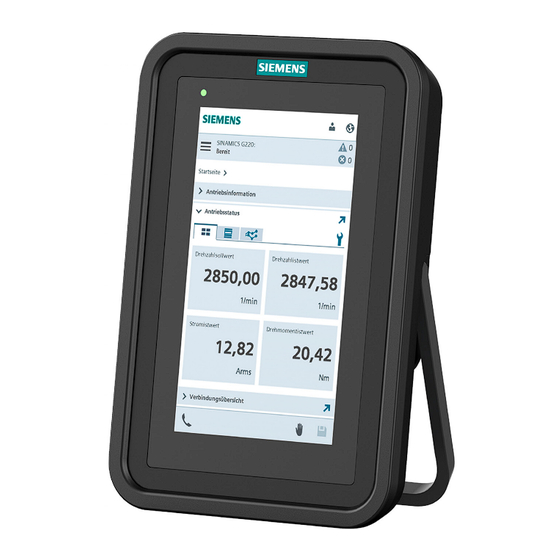
- Page 86 Using the Operator Panel with a converter 8.1 Home menu Drive status This function view can be configured to display specific values of various functions to monitor the actual converter activity. Figure 8-4 Drive status SINAMICS Smart Drive Interface SDI Pro 5.5'' Operating Instructions, 03/2024, FW V1.0, A5E52612203B AA...
- Page 87 Using the Operator Panel with a converter 8.1 Home menu Connection overview This function view displays the technical information of all the connected devices, such as the operating unit or PLC, converter, and motor. Figure 8-5 Connection overview SINAMICS Smart Drive Interface SDI Pro 5.5'' Operating Instructions, 03/2024, FW V1.0, A5E52612203B AA...
- Page 88 Using the Operator Panel with a converter 8.1 Home menu Current messages This function view shows a list of the current active faults and alarms. The faults and alarms can be acknowledged using the screen. Figure 8-6 Current messages Floating menu After the Operator Panel is connected to the converter, a floating menu icon appears on the home page of the converter integrated web server.
-
Page 89: Commissioning Menu
Using the Operator Panel with a converter 8.2 Commissioning menu Figure 8-7 Floating menu Commissioning menu Description This menu allows you to access the procedures to perform the various types of commissioning of the converter. 8.2.1 Quick setup Overview Quick setup comprises the basic settings that are required to commission the converter. SINAMICS Smart Drive Interface SDI Pro 5.5'' Operating Instructions, 03/2024, FW V1.0, A5E52612203B AA... - Page 90 Using the Operator Panel with a converter 8.2 Commissioning menu Description of function Figure 8-8 Quick setup In the quick setup, you define the most important properties of the drive, such as motor data, limit values, and the configuration of the inputs and outputs. When you have completed commissioning, the converter knows, for example, the data of the connected motor and has adapted its control interfaces to your requirements.
-
Page 91: Advanced Setup
Using the Operator Panel with a converter 8.2 Commissioning menu When you start commissioning, the converter creates a restore point. After each commissioning step, the converter saves the changes. If you cancel commissioning, the converter is reset to the restore point. Two modes are available for the quick setup: •... - Page 92 Using the Operator Panel with a converter 8.2 Commissioning menu Description of function Figure 8-9 Advanced setup In the advanced setup, you define drive options and functions to suit your application. During commissioning, you set the most important parameters of the converter. When you have completed commissioning, the converter knows, for example, the data of the connected motor and has adapted its control interfaces to your requirements.
-
Page 93: Safety Integrated Commissioning
Using the Operator Panel with a converter 8.2 Commissioning menu Two modes are available for the advanced setup: • "Start advanced setup" This option guides you through the individual steps to commission the converter at the advanced level. • "Start in read mode" To get to know the drive options and functions first, the commissioning can be started and run through in read-only mode. - Page 94 Using the Operator Panel with a converter 8.2 Commissioning menu Description of function Figure 8-10 Safety Integrated commissioning Changes to Safety Integrated settings are only possible in the "Safety Integrated commissioning" mode. The drive is in the safe state as soon as the commissioning mode is active.
-
Page 95: Monitoring And Operation Menu
Using the Operator Panel with a converter 8.3 Monitoring and operation menu Commissioning of Safety Integrated must be completely run through. No settings are applied if an interruption occurs during commissioning. When starting Safety Integrated commissioning, the converter creates a restore point. The converter saves the changes after every commissioning step. - Page 96 Using the Operator Panel with a converter 8.3 Monitoring and operation menu Description of function Figure 8-11 Drive status You can set this screen to display a variety of real-time values, such as speed setpoint and output frequency. You can see how the converter is working. The real-time values and labels displayed is preset in factory setting, and when required, can be modified using the icon .
-
Page 97: Inputs/Outputs
Using the Operator Panel with a converter 8.3 Monitoring and operation menu 8.3.2 Inputs/outputs Overview This function view shows the status of all inputs and outputs. Description of function Figure 8-12 Inputs/outputs This screen lists all the current settings for the digital inputs, digital outputs, analog inputs, and analog outputs as follows: •... -
Page 98: Diagnostics Menu
Using the Operator Panel with a converter 8.4 Diagnostics menu Diagnostics menu Description This menu allows you to have visibility of the present state of the drive as follows: • All active faults and alarms • Current and past events logs •... -
Page 99: Diagnostics Buffer
Using the Operator Panel with a converter 8.4 Diagnostics menu All faults can be acknowledged using the button on this screen. Using search and filter options, you can filter the results displayed on the screen and search for specific faults. 8.4.2 Diagnostics buffer Overview... -
Page 100: Safety Integrated
Using the Operator Panel with a converter 8.4 Diagnostics menu The information can be searched by text and by date range if necessary. The results of the search are displayed as a scrolling table at the bottom of the screen. The diagnostic buffer is kept when restoring factory settings via the backup and restore menu. - Page 101 Using the Operator Panel with a converter 8.4 Diagnostics menu The Safety Integrated comprises the following components: • Status of Safety Integrated Functions Displays the status of the Safety Integrated Function • Status Displays the internal events (limit violations, system errors) •...
-
Page 102: Connection View
Using the Operator Panel with a converter 8.4 Diagnostics menu 8.4.4 Connection view Overview This function view provides information about the connections in the drive system. Description of function Figure 8-16 Connection overview The individual components with IP address and additional details are graphically displayed in the connection overview. -
Page 103: Communication
Using the Operator Panel with a converter 8.4 Diagnostics menu 8.4.5 Communication Overview This function view provides information about the activated fieldbus protocol. Description of function Figure 8-17 Communication This screen displays the detailed status of the PZD telegrams currently being used by the converter. -
Page 104: Control/Status Word
Using the Operator Panel with a converter 8.4 Diagnostics menu 8.4.6 Control/status word Overview This function view provides information about the current status of the sequence control system. Description of function Figure 8-18 Control/status word This screen displays the real-time status of the control word sequence control and the status word sequence control. -
Page 105: Parameter Menu
Using the Operator Panel with a converter 8.5 Parameter menu Parameter menu Description This menu provides a variety of tools to search, view and create parameter lists. 8.5.1 Parameter list Overview This function view contains the converter parameters and enables the targeted modification of specific parameter values. -
Page 106: Backup And Restore Menu
Using the Operator Panel with a converter 8.6 Backup and restore menu This screen allows you to perform the following actions: • Create a simple view of all the parameters as a list on the screen • Create an advanced view of all the parameters as a list on the screen •... - Page 107 Using the Operator Panel with a converter 8.6 Backup and restore menu Description of function Figure 8-20 Backup and restore The following functions are available to back up and restore data and settings: • Save drive data to backup file Back up the settings to a file after commissioning.
-
Page 108: System Menu
Using the Operator Panel with a converter 8.7 System menu System menu Description This menu allows you to configure settings for the converter via the integrated web server. 8.7.1 Settings Overview This function view offers basic settings for the web server and the converter. Requirement •... -
Page 109: User Administration
Using the Operator Panel with a converter 8.7 System menu The following settings are available in this function: • Web server The web server provides options for saving changes automatically or manually and showing only standard parameters or all parameters. •... - Page 110 Using the Operator Panel with a converter 8.7 System menu Description of function Figure 8-22 User administration Users Under this tab, the web server provides a summary of the created users and offers the following functions: • Create new user accounts •...
-
Page 111: Protection & Security
8.7 System menu More information You can find more information about the user management and security settings in the SINAMICS Industrial Cybersecurity Configuration Manual (https://support.industry.siemens.com/cs/ww/en/view/109823969). 8.7.3 Protection & Security Overview In this function view, you can configure basic security settings using the Security Wizard. -
Page 112: Licenses
"trusted device". The web server cannot be accessed from the Operator Panel without a digital certificate. More information You can find more information on configuring secure communication in SINAMICS Industrial Cybersecurity (https://support.industry.siemens.com/cs/ww/en/view/109823969). 8.7.4 Licenses Overview You must purchase licenses for supplementary functions and options. - Page 113 Using the Operator Panel with a converter 8.7 System menu Description of function Figure 8-24 Licenses This function view offers the following functions: • Load and activate licenses Under "Trial License mode and licenses", you upload license files created with the Web License Manager.
-
Page 114: Firmware Update
Using the Operator Panel with a converter 8.7 System menu 8.7.5 Firmware update Overview This function view displays the current version of the firmware and of the web server. You can perform a firmware update in the web server: • For an upgrade, the converter settings are retained. •... -
Page 115: About Web Server
Using the Operator Panel with a converter 8.7 System menu Prerequisites for transferring the firmware file to the converter: • The motor is switched off, that is, the converter is not in the "Operation" state. • The power supply to the converter is not interrupted while the firmware is being transferred. - Page 116 Using the Operator Panel with a converter 8.7 System menu Under "Versions" you can see the revision levels of the web server and the loaded firmware. Under "Third-party software" there is a link to information about any third-party software used. After you tap the link, the license conditions are loaded to the user memory of the Operator Panel in the file "READ_OSS.ZIP".
-
Page 117: Technical Data
Technical data Technical data of the Operator Panel Table 9- 1 Technical data of the Operator Panel Property Specification Power supply 20 V DC ... 29 V DC • Power supply via converter service interface X127: 24 V DC • External power supply: 24 V DC Max. - Page 118 Technical data SINAMICS Smart Drive Interface SDI Pro 5.5'' Operating Instructions, 03/2024, FW V1.0, A5E52612203B AA...
Need help?
Do you have a question about the SINAMICS SDI Pro and is the answer not in the manual?
Questions and answers