Table of Contents
Advertisement
Quick Links
CUSTOMER
Order toll-free in the U.S. 24 hours, 7 A.M. Monday to midnight Friday: 877-877-BBOX
FREE technical support, 24 hours a day, 7 days a week: Call 724-746-5500 or fax 724-746-0746
SUPPORT
Mail order: Black Box Corporation, 1000 Park Drive, Lawrence, PA 15055-1018
INFORMATION
Web site: www.blackbox.com • E-mail: info@blackbox.com
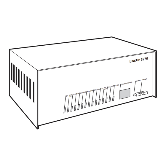
LinkUp 3270
X D R
D R
T E T X
D C E D
S Y S
O N
C K
C H A N
IO F L T
R X C
T X C
R I/
D
R C
S Y N
R D S
S D T
T S C T
APRIL 1997
PCM71
PCM92
3 2 7 0
U
P
I N K
L
T
R E S E
L
C H S E
R R O R
N E L /E
Advertisement
Table of Contents

Subscribe to Our Youtube Channel
Related Manuals for Black Box LinkUp 3270


Summary of Contents for Black Box LinkUp 3270
- Page 1 Order toll-free in the U.S. 24 hours, 7 A.M. Monday to midnight Friday: 877-877-BBOX FREE technical support, 24 hours a day, 7 days a week: Call 724-746-5500 or fax 724-746-0746 SUPPORT Mail order: Black Box Corporation, 1000 Park Drive, Lawrence, PA 15055-1018 INFORMATION Web site: www.blackbox.com • E-mail: info@blackbox.com...
- Page 2 LINKUP 3174 FEDERAL COMMUNICATIONS COMMISSION RADIO FREQUENCY INTERFERENCE STATEMENT This equipment generates, uses, and can radiate radio frequency energy and if not installed an used properly, that is, in strict accordance with the manufacturer's instructions, may cause interference to radio communication.
-
Page 3: Table Of Contents
LINKUP 3174 CONTENTS SPECIFICATIONS............................7 INTRODUCTION............................8 Using the Manual........................9 Summary of Features ........................11 2.2.1 Hardware Options ......................11 2.2.2 ASCII Devices Supported.....................12 2.2.3 Terminal Emulation .....................12 2.2.4 Printer Emulation......................12 2.2.5 Personal Computer Support..................12 2.2.6 Emulation and Processing ...................12 2.2.7 Optimized Display Output and Terminal Support.............12 2.2.8 Status Line Emulation....................13 2.2.9... - Page 4 LINKUP 3174 HARDWARE DESCRIPTION........................30 Front-Panel Controls.........................30 Channel-Status Indicators......................31 System-Status Indicators ......................31 Error-Code Display........................32 Back Panel ..........................32 PORT TEST AND SYSTEM MANAGEMENT ..................33 General Information.........................33 Port Test Mode Menu and Functions ..................34 System Management Mode Menu and Functions..............34 CONFIGURATOR MODE........................47 General Information.........................47 6.1.1 Help Messages During Configuration.................47 6.1.2...
- Page 5 LINKUP 3174 8.1.2 Non-Standard Functions ....................93 8.1.3 Special Functions......................93 Data Presentation........................94 SUPPORT FOR SPECIAL OUTPUT DEVICES ...................96 Pseudo-Transparency ........................96 9.1.1 Mode Select and Deselect Commands................97 9.1.2 Special Considerations and Limitations ..............97 9.1.3 Special Applications Examples ..................97 SAS Graphic Transparency .......................97 9.2.1 Special Considerations ....................98 Computer-to-Computer Applications (COMPU) ..............98...
- Page 6 LINKUP 3174 15.3.1 Dialback System (DBSYS) Configuration ..............122 15.3.2 Dialback Port Configuration..................123 15.3.3 Audit-Trail Configuration ..................123 15.3.4 Configuring Modem Personalities ................124 15.3.5 Syntax Of Modem Command Strings ...............126 15.3.6 Modem Command Strings and RAM Use..............127 15.3.7 Configuring Dialback User Personalities ..............127 15.3.8 Real-Time Clock Configuration.................129 15.4 Operation ..........................130...
- Page 7 LINKUP 3174 E.18 D450 Terminal Module—Data General Dasher D400/D450..........198 E.19 DISPH Terminal Module—Nortel Displayphone ..............201 E.20 DISPI Terminal Module—Norttel Displayphone..............205 E.21 DM5 Terminal Module—Beehive DM-5 ................208 E.22 DM5AB Terminal Module—Beehive DM-5A/B..............212 E.23 DM20 Terminal Module—Beehive DM-20/Standard/Plus ..........215 E.24 DM78 Terminal Module—Beehive DM-78 ................221 E.25 FORTU Terminal Module—Fortune Videotex 32:16 ............225 E.26...
-
Page 8: Specifications
LINKUP 3174 1. Specifications Memory — 256-768K RAM Ports — Up to 34 total (32 async, 2 sync) (serial) Base Unit: 2 synchronous channels; bit rates up to 19.2 Kbps on Channels — RS-232C/V.24 interfaces Async Expansion Board: Four async channels (RS-232C/V.24 or RS-422/V.11), or eight async channels (RS-232C) with DB9 connectors;... -
Page 9: Introduction
LINKUP 3174 2. Introduction The LinkUp 3174 allows connection of modem eliminator and in general takes the place asynchronous terminals and printers to IBM ® of a remote IBM 3174 Control Unit. compatible host computers (for example, Model The LinkUp 3174 has two synchronous ports 360, 370, 43XX and 30XX mainframes). -
Page 10: Using The Manual
CHAPTER 2: Introduction System/3270 Host IBM 37XX Sync Modems RS-232C Sync Modems LinkUp 5294 DataLynx /5294 IBM 37XX LinkUp 3174 with STD 3174 System/3270 SYS OK DCE RI/SYN TXC I/O FLT CHANNEL ERROR CH SEL RESET Firmware Host RS-232C ASCII Terminal RS-232C ASCI Printer RS-232C... - Page 11 Black Box. • CHAPTER ELEVEN — Packet Network Access • APPENDIX E — List of Supported Terminals. (PNA) Applications. Explains how to use the This lists all the terminals supported by the LinkUp 5294 in X.25 and other packet data...
-
Page 12: Summary Of Features
CHAPTER 2: Introduction 2.2 Summary of Features This section describes the device support capabilities of the LinkUp 3174 and the emulation techniques which it employs. The LinkUp 3174 is shown in Figure 2-2. 3174 LinkUp 5294 SYS OK DCE RI/SYN TXC I/O FLT CHANNEL ERROR CH SEL... -
Page 13: Ascii Devices Supported
LINKUP 3174 2.2.2 ASCII D 2.2.6 E EVICES UPPORTED MULATION AND ROCESSING The LinkUp 3174 provides support for many Each LinkUp 3174 can provide emulation for commonly used ASCII terminals as well as the IBM 128 sessions. The number of devices is specified Personal Computer and full compatibles. -
Page 14: Status Line Emulation
CHAPTER 2: Introduction especially advantageous when remote terminals Up to 16 passthrough sessions are available, and with low baud rates are employed. each may be password-protected if desired. It is recommended, however, that no more than ten 2.2.8 S TATUS MULATION passthrough sessions be run concurrently (eight if an IBM host session is also in progress). - Page 15 LINKUP 3174 active at one time: 32 displays and 32 auxiliary to the asynchronous host. Passthrough ports are printers.) assigned while in Configurator Mode using the async port configuration menus. A terminal attached to one physical port may select and use any available Logical Unit for •...
- Page 16 CHAPTER 2: Introduction IBM Host Modem Modem DataLynx /5294 3174 LinkUp 5294 SYS OK DCE RI/SYN TXC I/O FLT CHANNEL ERROR CH SEL RESET ASYNC ASYNC PORT 2 PORT 9 ( PASSTHROUGH ) Terminal ASYNC Minicomputer Figure 2-3. Typical LinkUp 3174 Passthrough Application. Printers (LU type PRT) are directly attached to number or the name of a previously defined the LinkUp 3174 using an RS-232C serial...
-
Page 17: Virtual Logical Unit Operation
LINKUP 3174 As far as the host computer is concerned, both 2.4 Virtual Logical Unit Operation printer types are identical. The host identifies and addresses the attached devices by the LU Since the LinkUp 3174 design separates the logical number, not the port number. Consequently, unit (LU) from the physical port, a means of both printer types appear to be independent controlling access to the LU must be provided. - Page 18 CHAPTER 2: Introduction Path 2 IN USE STATE Fault or inactivity timeout Is a zero Path 2 reconnect time limit specified? Path 3 RECONNECT STATE Has the Has user reconnect time limit cmpleted reconnect elapsed? sequence? Path 5 Is a Path 7 forced logoff sequence configured?
-
Page 19: Logical Unit States
LINKUP 3174 2.4.1 L 2.4.2 L OGICAL TATES OGICAL TATE RANSITIONS • Path 1: Disconnect to In-Use Transition — This For simplicity in the following discussions, the term transition path occurs when the proper Connect "terminal" is used to mean any device capable of Mode procedure is completed by the operator. -
Page 20: Configuration Considerations
CHAPTER 2: Introduction • Path 7: Reconnect to Disconnect Transition — NOTE This transition is also due to a reconnect If the Printer LU is set for SHR a LOC timeout but differs from the conditions Operational Mode when configuration described in Path 6 in that a Forced Logoff changes are made, any In-Use display Message has not been defined, so no message is... -
Page 21: Installation
3174. A typical local installation to a single host is to see that the above items are present. If an item is described. Attachment of local and remote (to the missing or defective, call Black Box. LinkUp 3174) terminals and printers is also NOTE included in Sections 3.3, 3.4, and 3.5. -
Page 22: Set Up The Configuration Terminal
CHAPTER 3: Installation 3.1.3 S 3.1.4 C P THE ONFIGURATION ERMINAL ONNECT THE ONFIGURATION ERMINAL Ensure that the configuration terminal is set for Connect the terminal to Port 2 of the LinkUp 3174 initial operation with the following values: using a standard RS-232C cable. Figure 3-1 below shows the location and numbering scheme of both •... -
Page 23: Establish Communication
LINKUP 3174 3.1.5 E When you power on a LinkUp 3174 that STABLISH OMMUNICATION is configured to run from the Power on both the LinkUp 3174 and the terminal. secondary microcode bank, the boot When the LinkUp 3174 is powered on, all the LEDs process begins initially from the on the front panel will illuminate briefly, and “88”... -
Page 24: Accessing The Linkup 3174 Configurator
CHAPTER 3: Installation NOTE 4.Select Option 1, Configurator Mode, from the System Management Mode menu. The prompt A question mark <?> followed by Enter Item(s) to be Configured: will appear, <Enter> is a valid response at any time indicating that you are in Configurator Mode. during Connect and Configuration Refer to CHAPTER FIVE for complete details Modes. -
Page 25: Line Configuration
LINKUP 3174 3.4.1 L 3.5 Connecting Printers ONFIGURATION Modems on the LinkUp end of switched lines Printers may be connected to the LinkUp 3174 in should permit the following: one of two ways. Printers using a serial interface • Auto-answer mode. (RS-232C cable) may be connected directly to the LinkUp 3174 using one of the asynchronous ports. -
Page 26: Auxiliary Printers
CHAPTER 3: Installation 3.5.3 A 3.6 Connecting the LinkUp 3174 to the Host UXILIARY RINTERS Computer The following considerations apply to auxiliary printers attached to directly or remotely connected The LinkUp 3174 can be attached to the host terminals. front end in one of three ways, as shown in 1.Verify that the auxiliary port of the chosen Figure 3-2. - Page 27 LINKUP 3174 modem; thus, the LinkUp 3174 bit rate must be set Method 3: for EXTERNAL Clocking. Refer to the modem This method is similar to Method 1 except that a manufacturer's literature for setting the modem for modem eliminator is used in place of the pair of Internal Clocking and Carrier Controlled by modems and the intervening line.
-
Page 28: Requirements
CHAPTER 3: Installation 3.6.1 R 3.6.2 D EQUIREMENTS NSTALLATIONS Before connecting to the host, obtain the following If the dual host option is used, make sure that the information so that you can configure the LUs you configure for use on Sync Port 0 have synchronous ports correctly. -
Page 29: Connecting The Linkup 3174 To An Asynchronous Host Computer
LINKUP 3174 3.7 Connecting the LinkUp 3174 to an Asynchronous Host Computer Asynchronous terminals may be connected through the LinkUp 3174 in one of two ways as depicted in Figure 3-3. No special host software is required. ASYNC HOST RS-232C Sync Modems RS-422 Async... -
Page 30: Data Cable Pin Specifications
CHAPTER 3: Installation 3.8 Data Cable Pin Specifications 3.8.3 A RS-232C C SYNCHRONOUS ABLES WITH ONNECTORS Cable requirements for both asynchronous and Cable pinouts for the RS-232C DB9 connector are synchronous interfaces are given in the following shown below: sections. Pin 1 Data Carrier Detect (DCD) 3.8.1 A... -
Page 31: Hardware Description
LINKUP 3174 4. Hardware Description The front panel of the LinkUp 3174 is shown in Figure 4-1. Status indicators monitor power and the selected channel used for display of RS-232C line signals. To simplify operation, only two operator controls are provided. Use of the front panel buttons is discussed in Section 4.1. -
Page 32: Channel-Status Indicators
CHAPTER 4: Hardware Description 4.2 Channel-Status Indicators • CD (Carrier Detect) — This LED is lit when the LinkUp 3174 has detected a carrier signal from a remote modem. If no detectable carrier signal The LinkUp 3174 is equipped with a full RS-232C is present, or if the remote modem hangs up, status display capable of monitoring the status of this LED will be turned off. -
Page 33: Error-Code Display
LINKUP 3174 4.4 Error-Code Display When a program-detectable error occurs, all channel-status indicators are turned off and a two- or three-level error code is displayed using the two- digit channel display. The error codes are flashed alternately. For further information on diagnostics and troubleshooting, refer to Appendix D. -
Page 34: Port Test And System Management
CHAPTER 5: Port Test and System Management Modes 5. Port Test and System Management This section describes Port Test and System 5.1 General Information Management Modes. General information, such as accessing the different modes, is provided in Port Test Mode and System Management Mode Section 5.1. -
Page 35: Port Test Mode Menu And Functions
LINKUP 3174 5.2 Port Test Mode Menu and Functions 3.Character Display Test (Option 3). This function is used to test the terminal screen for proper display of the alphanumeric characters. The Port Test Mode menu is shown below. Type the PAPER/3278 operators may find this option number corresponding to the function to be useful for testing the condition of the print... - Page 36 CHAPTER 5: Port Test and System Management Modes after successful entry of the old one. After the correct password has been entered, the System Management Mode option menu is displayed. The menu shown below represents firmware versions 6.21 and above. Earlier versions of firmware display the menu options in a single column.
- Page 37 LINKUP 3174 All of the menu options are explained in the Sync Port Address Trace (Option 3, All Models) following paragraphs. To exit System Management This option displays each control unit address as Mode, and return to Connect Mode, type either it appears in the synchronous data stream.
- Page 38 CHANNEL/ERROR window since the LinkUp’s last power-up will also be displayed. Pressing R deletes them from the screen and erases them from memory. Record all the values shown on this screen for Black Box if a problem must be reported.
- Page 39 LINKUP 3174 Deact/Act Async Port (Option 7, All Models) • The two-byte CRC is included in inbound messages to the LinkUp 3174. A sync port This option is provided to allow the system manager trace is shown below. to deactivate or activate an asynchronous port without affecting the others.
- Page 40 CHAPTER 5: Port Test and System Management Modes LU and Async Port Summary (Option 23, All Four keys are active during this test, as follows: Models) • <N> (for NEXT) displays the next page of data This function displays certain configuration •...
- Page 41 LINKUP 3174 The Async Port Summary is shown below: Port Number Device Type ADM3A ADM3A ADM3A ADM3A ADM3A ADM3A ADM3A ADM3A DTE/DCE Bit Rate Auto Auto Auto Auto Auto Auto Auto Auto No. of Bits Parity None None None None None None None...
- Page 42 CHAPTER 5: Port Test and System Management Modes CAUTION Values for items 1 through 5 are displayed as decimal numbers between 0 and 65535. Item 6 is This will unconditionally reset the counted to 131070. If these maximum displayable LinkUp 3174. Any operator connected values are reached, the counters are not when this function is invoked is not automatically reset.
- Page 43 LINKUP 3174 Performing System Transfer Utilities 5. At the DOS prompt, press <Alt/Caps Lock> or <Shift/Shift> simultaneously to Hotkey into Before executing a system transfer utility for the Terminal Emulation Mode. first time, perform the following procedures: 6. Press <Enter> once or twice to obtain the 1.Load the following programs onto a personal LinkUp 3174 banner message.
- Page 44 CHAPTER 5: Port Test and System Management Modes Operation Completed Successfully. Press ENTER Operation Was Successfully Completed. to Continue. Please Hotkey to Emulation Mode. When <Enter> is pressed, the System Transfer Press <Alt/Caps Lock> or <Shift/Shift>. LinkUp Utilities menu will be redisplayed. Type [END] 3174 will display the following message: followed by <Enter>...
- Page 45 If any problems occur during the microcode this option. A new version of firmware sent from download, the operation is automatically aborted Black Box on diskette can be loaded directly from and an error message appears on the personal your personal computer into LinkUp 3174's computer screen.
- Page 46 Effectively, what the Switch Microcode option has Black Box. It would be helpful to get the CRC done is inserted (or removed) a command numbers from the Option 5, Product...
- Page 47 LINKUP 3174 NOTE If the system manager is performing this procedure remotely, via network or via modem, then the LED window cannot be seen. In this case, the errors may be overlooked. Set Date/Time (Option 27, SNA and HV Only) SET REAL TIME CLOCK Current Date: 0000/00/00 Current Time: 00:00:00...
-
Page 48: Configurator Mode
CHAPTER 6: Configurator Mode 6. Configurator Mode Configurator Mode is used to change the parameter Connect Screen values for: Enter Logical Unit ID (LU2): 1 • Synchronous ports • Asynchronous ports Port Test Mode • Logical Units Enter Choice: 1 •... -
Page 49: Consistency Checking
LINKUP 3174 The Help Screen for the Enter Item(s) to be Most configuration parameters are frozen when a Configured: prompt is shown below. Logical Unit or Passthrough Unit is assigned to an Access Group. This prevents configuration changes from being made until the LU or PTU is removed Enter one of the following items: from the group. -
Page 50: Configurator Mode Commands
CHAPTER 6: Configurator Mode 6.1.4 C The <?> (Help) Command ONFIGURATOR OMMANDS Configuration commands are entered from the During configuration, help messages are available terminal keyboard. The LinkUp 3174 always at two levels. To illustrate this, assume you type provides a prompt whenever a response is required. PORT 2 <Enter>... - Page 51 LINKUP 3174 The <CTRL/X> (Delete Entry) Command When this particular menu is exited with the END command, the LinkUp 3174 takes you out of This command deletes the current entry. This may Configurator Mode and displays the following be more convenient than the single-character message on your screen: backspace or rubout key for correcting typing errors.
-
Page 52: Configuration Procedures
CHAPTER 6: Configurator Mode When the Enter Item(s) To Be Configured: prompt 6.Configure the async port to which your terminal is attached (if necessary). is displayed, the <Enter> key alone increments to the next item in the above sequence. This is Sections 6.4 through 6.9 describe the configuration particularly useful the first time the LinkUp 3174 parameters and options for synchronous and... -
Page 53: Exclusions And Exemptions
LINKUP 3174 As another example, suppose you have already 6.4 Synchronous Port Parameters configured LU 6 for a particular use and you now want to configure LUs 2 through 5 in the same way. The Synchronous Port configuration menu with In response to the Enter Item(s) to be Configured: default values for SNA is shown in below. - Page 54 CHAPTER 6: Configurator Mode 3. Control Unit Number required whenever the first hex digit is in the range A to F for both SNA and BSC. For SNA, the Control Unit Number is specified in hex format as a value in the range 1 to 0FF. (Hex 0 If both Ports 0 and 1 are used, they may have the is reserved and hex 0FF is the SDLC Broadcast same CU Number.
- Page 55 LINKUP 3174 4. Communications Interface However, if the LinkUp 3174 is located adjacent to the host computer and is connected directly to a If the LinkUp 3174 is connected to the host host port, it has its own built-in modem eliminator. computer by modems or line drivers (modem In this case, its Communications Interface must be eliminators) on either a point-to-point...
- Page 56 CHAPTER 6: Configurator Mode 7. Half/Full Duplex Line 9. Physical Unit ID (SNA Only) A half-duplex line is one that can transmit data in The physical unit ID is a unique 10-digit hex one direction at a time, while a full-duplex line identification that is included in the response to an transmits data in both directions at the same time.
-
Page 57: Asynchronous Port Parameters
LINKUP 3174 11. Enable NetView Alerts (SNA Only) 1. Device Type Specify Y to enable the LinkUp 3174 generation of The range of device types supported by the LinkUp unsolicited alerts. Specify N to disable this feature. 3174 is constantly being expanded. The list of those currently supported may be displayed through the The default setting for this parameter is N. - Page 58 CHAPTER 6: Configurator Mode If the device attached to this port is a Passthrough Unit, this parameter may be specified as PTU 2 through PTU 17, where the PTU configuration defines the async passthrough port (that is, Device Type = Host). An Access Group may be specified for this parameter.
- Page 59 LINKUP 3174 4. Bit Rate 8. Connect Mode The supported asynchronous bit rates are 75, 110, For a terminal or printer connected directly to the 134, 150, 300, 600, 1200, 2000, 2400, 4800, 7200, LinkUp 3174 or by a fixed point-to-point line using 9600, 14400, 19200, and AUTO (Autobaud).
- Page 60 CHAPTER 6: Configurator Mode which can generate data at a rate faster than the 3174 to terminate In-Use State, ending the receiving device is capable of processing it. After passthrough session and freeing the host port for the LinkUp 3174 transmits an X-OFF, it can accept other passthrough sessions.
- Page 61 LINKUP 3174 The allowed choices for RS-422 operation are as 13. Auto-Skip Enable follows: This is for use with Parameter 12 (Packet Network 3 = DCE Access) only. If this option is disabled, the operator is required to use the <TAB> key to move to the 9 = X-ON, NONE next field even if the host application has defined the field as Auto Skip.
-
Page 62: Logical Unit Parameters For A Display
CHAPTER 6: Configurator Mode 6.6 Logical Unit Parameters for a Display 1. Buffer Size This parameter provides emulation of the various A typical configuration menu with default values for models of the 3278 display terminal. The valid a Display Logical Unit is shown below. buffer sizes and associated screen formats are shown in Table 6-3. - Page 63 LINKUP 3174 Table 6-3. Alternate Screen Format Buffer Sizes The default for this parameter is NONE. 4.Reconnect Time Limit 3278 Alternate Format Model Buffer Size # rows #cols. Options for this parameter are integer values from 0 to 99 minutes, and NONE. This specifies the length of time that the LinkUp 3174 maintains a 1920 session between a disconnected terminal and the...
- Page 64 CHAPTER 6: Configurator Mode If neither TermSelf nor Forced Logoff Data is Disabling echoplex is primarily intended for desired, specify NONE. computer-to-computer applications (see Section 9.3) and file transfer. For BSC protocol, if the attention code is specified as a PA key or the <CLR>key, then data need not be The default for this parameter is Y.
- Page 65 LINKUP 3174 NOTE NOTE This parameter may be changed even if This parameter may be changed even if the LU is a member of an Access the LU belongs to an Access Group. Group. If during global configuration a Also, if during global configuration a new value is not entered for this new value is not entered for this parameter, the existing value of the...
-
Page 66: Logical Unit Parameters For A Printer Or Auxiliary Printer
CHAPTER 6: Configurator Mode 16. Numeric Field Check Enable 6.7 Logical Unit Parameters for a Printer or Auxiliary Printer While in Emulation Mode, the LinkUp 3174 normally checks each input field, and will not allow The Logical Unit configuration menus for Printers alpha characters to be entered into numeric- only and Auxiliary Printers are shown below. - Page 67 LINKUP 3174 2. Operational Mode 6. Single/Dual Case The printer LU may be specified for Local Copy Specify D (Dual Case) if both upper and lower case (LOC) use only, Host System (SYS) use only, or printing is required, or S (Single Case) if upper shared (SHR) use.
-
Page 68: Passthrough Unit Parameters
CHAPTER 6: Configurator Mode 12. Alternate Translate Table (Parameter 11 on PRT For complete 8-bit transparency in async menu) passthrough operation, the attention code should be set to NONE. To end the passthrough session, Valid options for this parameter are Y and N. If set the directly connected operator should then power to Y, a special EBCDlC-to-ASCII translate table is the terminal off and back on. -
Page 69: Using The Access Group Menu
LINKUP 3174 in Section 6.3. In the above example, after entering JACK = 10-13,15,17-20, the following message ***LOGICAL UNIT ACCESS GROUP MENU*** appears: Access Group == Logical Unit Members THIS MAY RECONFIGURE LU/PTUs WITH 2-5, 7 LU/PTU 10 AS BASE. PROCEED? (Y/N) Enter Change(s): A response of Y or YES will result in LUs 11-13, 15, and 17-20 being reconfigured the same as LU 10,... -
Page 70: Translate Tables
CHAPTER 6: Configurator Mode display a list of valid formats. configuration as LU 10. If so, LU 10 may be included in JIM. Otherwise, the following message As with all other Configurator Menus, an <Enter> will be displayed: will redisplay the table showing all current settings. Base LU/PTU in conflict with Group LU/PTU(s) To cancel changes to the table, type QUIT in belonging to another Access Group... -
Page 71: Accessing The Translate Table
LINKUP 3174 through the ASCII translation table and are 6.10.2 U SING THE RANSLATE ABLE exchanged with their 8-bit counterparts (00H From the Translate Table menu, the operator may through 0FAH). perform any of the following functions: NOTE 1.Make any required changes. If the table cannot be read successfully 2.Ask for help. -
Page 72: Translate Table Error Messages
CHAPTER 6: Configurator Mode Changed table entries do not take • ASCII VALUE OUT OF RANGE: Indicates that the ASCII value is not in the range 21-7E. For effect immediately. The new values example: take effect only when a Remote Reset is executed (refer to Section 5.3 for A2<=>9C details) or when the LinkUp 3174 is... -
Page 73: Configurator Mode Error Messages
LINKUP 3174 6.12 Configurator Mode Error Messages Specify Banner Message Currently: (NONE) While you are entering configuration changes, a number of syntax or semantic errors may be detected by the LinkUp 3174. These will result in the display of an error message in the following format: nn:<message>... -
Page 74: Configuring A Terminal Module
CHAPTER 7: Configuring A Terminal Module 7. Configuring A Terminal Module This chapter describes the Terminal Configurator, Connect Screen an extended function of Configurator Mode which Enter Logical Unit ID (LU2): 1 allows the system manager to customize or completely define a terminal module. This is necessary when the asynchronous terminal used with the LinkUp 3174 is not specifically supported. -
Page 75: Terminology And Definitions
<NUMERIC OVERRIDE>. Key Sequence Menus in case you have to alter it later, or in case you have are described in Section 7.9. to call Black Box for assistance. 7.2 Terminology and Definitions Before going online to the host, test the module by using the Character Echo Test and/or the Async Port Trace facility. -
Page 76: Data Entry Formats And Commands
CHAPTER 7: Configuring A Terminal Module 4.The LinkUp 3174 needs to know the [CLEAR • KEYS n — To go to the nth key sequence menu. SCREEN] sequence for the terminal used. If a • HEX — To switch to hexadecimal key entry non-standard terminal is used for configuration, mode. -
Page 77: Special Commands
LINKUP 3174 7.4.2 S <BACKSPACE> or <RUBOUT> PECIAL OMMANDS Unless otherwise stated, all commands are followed These keys can be used during configuration to by <Enter>. correct typing mistakes. The command deletes the last character of the current entry. The ? (Help) Command The <CTRL/>... -
Page 78: Data Presentation Formats
CHAPTER 7: Configuring A Terminal Module The [PREV] Command hardcopy device terminal module, HCOPY should be specified. This displays the previous menu. NOTE The [INFO n] Command Some existing terminal drivers are too This command displays the nth Information Menu. large to be safely used as Base Terminal Modules. -
Page 79: Display Terminal Information Parameters
LINKUP 3174 3. Specific Information Parameters sequence. If no sequence is desired, use HEX mode to enter NONE. These menus are used to specify general terminal information. The values shown differ depending on 7.7 Display Terminal Information Parameters the base terminal module used. The base driver used in the example is ADM3A. - Page 80 CHAPTER 7: Configuring A Terminal Module 2. Device Class 10. Intensified Fields At the present time the only device classes are Display Terminals: If your terminal supports dual DSPLY and HCOPY. The device class cannot be intensity or colon, specify Y. Otherwise, specify N. changed.
- Page 81 LINKUP 3174 13. Status Line 16. Pass Carriage Control Display Terminals: Specify Y if your terminal has a This feature allows carriage-control characters to be separate status line. N causes the status line to show used as record delimiters in computer-to-computer on the last line of the display.
-
Page 82: Function Sequence Menus
CHAPTER 7: Configuring A Terminal Module 7.8 Function Sequence Menus Current Values for Function Sequences 1 -12 (T5 = T5): These menus are used to define the sequences that 1. Startof Screen the LinkUp 3174 sends to the terminal. 2. Forward One Position 3. - Page 83 LINKUP 3174 7. Cursor Positioning • CAl — Represents the column number by a two- byte sequence (each byte starting at 40H). This sequence moves the cursor to a specific row Example: COL 1-40 41; COL 80-45 50. and column on the screen. Many terminals use a •...
- Page 84 CHAPTER 7: Configuring A Terminal Module 8. Set Unprotected Standard Intensity Current Values for Function Sequences 13 - 24 (T5 = T5): This sets the intensity for an unprotected normal- 13. De-lnitialize Terminal 0E EM WT 03 intensity field. If you specified N for Intensified 14.
- Page 85 LINKUP 3174 • Online — See Notes 1, 5 15. Select Large Screen • Full Duplex — See Notes 1, 4 This is the sequence sent by the LinkUp 3174 to the terminal to select 132-column mode. This also • Keyboard Unlock — See Notes 3, 5 requires that you specify 132 for Number of Columns in the Terminal Information Menu.
-
Page 86: Key Sequence Menus
CHAPTER 7: Configuring A Terminal Module beginning of each line on your printer and the 24. Status Line characters are the same as the characters in the This sequence is sent to the terminal to address the select or deselect sequence, the problem may be Status Line. - Page 87 LINKUP 3174 When using literal key-sequence entry mode 3. Down Cursor with X-ON/X-OFF flow control enabled, be This key moves the cursor down one position careful not to generate an X-OFF (<CTRL/S>). without destroying the contents of the new or old If you should do this, send an X-ON cursor position.
- Page 88 CHAPTER 7: Configuring A Terminal Module 8. Backtab 14 Erase To End of Field This key moves the cursor to the first character in This key clears the character location occupied by the previous unprotected field if the cursor is on the cursor and all remaining character locations to the attribute or in a protected field.
- Page 89 LINKUP 3174 18. Sys Request Current Values for Keys 27-39 This key switches between SSCP-LU session and LU- 27. PF9 1B 39 LU session. 28. PF10 1B 30 29. PF11 1B 51 Recommended Keys: <SYS REQ>; [ESC ?] 30. PF12 1B 57 31.
- Page 90 CHAPTER 7: Configuring A Terminal Module Specify NONE. Current Values for Keys 53 - 64(T5 = T5): 51. Test 53. Fast Backspace NONE 54. Numeric Override 1B SB This key initiates an operator-generated Netview 55. Refresh Screen Alert. 56. Initialize Terminal 1B 3C 57.
- Page 91 LINKUP 3174 60. Request Disconnect NOTE This is a special function that causes the LinkUp The following functions are for 3174 to send a [DEINITIALIZE TERMINAL] hardcopy terminals only. See Chapter 8 sequence to the terminal and then to drop Data for further information on hardcopy Terminal Ready (DTR) if in DTE mode or Data Set support.
- Page 92 CHAPTER 7: Configuring A Terminal Module Rubout Erase Field Hardcopy Terminals: This key deletes the character Hardcopy Terminals: If the cursor is located in an preceding the current print-head position. unprotected field4 this key deletes the entire field Typically, this is the last character typed in. contents.
-
Page 93: Support For Hardcopy Terminals
LINKUP 3174 8. Support For Hardcopy Terminals The PAPER/3278 Feature permits the use of The remaining keyboard functions are grouped hardcopy terminals with the LinkUp 3174. into three categories: Supported hardcopy terminals include the Texas • Standard Functions - functions that closely Instruments ®... -
Page 94: Non-Standard Functions
CHAPTER 8: Support for Hardcopy Termimals • ERASE INPUT — <ERASE INPUT> results in all 8.1.3 S PECIAL UNCTIONS unprotected fields being erased and the cursor Five special keyboard functions are provided with being logically moved to the Home position of PAPER/3278 to allow the user to control the data- the screen. -
Page 95: Data Presentation
LINKUP 3174 8.2 Data Presentation • FIELD ID SWITCH — The Field ID Switch is provided to assist in the identification of Input Data unprotected field locations in formatted data applications. If this feature is OFF, formatted During keyboard input, the print head will wrap to screen printout appears much like it does on the next line automatically after it reaches the end actual CRT terminals. - Page 96 CHAPTER 7: Configuring A Terminal Module PERSONNEL DATA NAME: TELEPHONE: ADDRESS: CITY: ZIP: PREVIOUS EMPLOYERS: ***END OF EMPLOYEE RECORD. Figure 8-2. Formatted Screen Printout—With No Field Identifiers. Unformatted Output Unformatted output is typically used for simple interactive inquiry/response or list-display applications.
-
Page 97: Support For Special Output Devices
LINKUP 3174 9. Support for Special Output Devices The LinkUp 3174 is designed to support specialized 9.1 Pseudo-Transparency devices which are not normally found in a 3270 environment. For example: Pseudo-transparency is used for output from the host to a peripheral device, usually a printer or •... -
Page 98: Mode Select And Deselect Commands
CHAPTER 9: Support For Special Output Devices 9.1.1 M 9.1.3 S ELECT AND ESELECT OMMANDS PECIAL PPLICATIONS XAMPLES 1.Specialty printer-control sequences are readily The trigger command for selection of pseudo- output by the LinkUp 3174 using the transparency mode is the two-character sequence: [| transparent data approach. -
Page 99: Special Considerations
LINKUP 3174 Host data is translated to ASCII in the host and 9.3 Computer-to-Computer Applications then converted by adding 80H to all ASCII values (COMPU) between 00H and 7EH. Note that 7FH is not converted. This transmits data with values from 7FH For operators who wish to provide communications to FEH down the line without interfering with SNA between IBM host computers and either micro,... - Page 100 CHAPTER 9: Support For Special Output Devices Data sent to the IBM host should be formatted as if Since input characters are not examined during it was coming from a keyboard. For example, if the keyboard-locked state, care should be taken to contents of the device buffer in the LinkUp 3174 ensure that inbound data, such as an alpha represent an unformatted screen for a 3278 Model...
-
Page 101: Generate/View Attributes
LINKUP 3174 10. Generate/View Attributes The LinkUp 3174 provides two extensions to the 10.2 Generate Attribute Characters 3278 keyboard functions: Attribute characters may be inserted at any position • View attribute characters on the screen in order to experiment with screen layout design and testing. - Page 102 CHAPTER 10: Generate/View Attributes Table 10-1. Encoding to Generate and Display Field Attributes Hex value Display-code Protect/ Alpha/ Intensity Detectable Modified (Generate character for Unprotected Numeric Data Tag Attribute View Attribute Function) Function KEY: U=Unprotected P=Protected A=Alphanumeric #—Numeric S=Standard H=High ND=Non-display Y=Yes N=No...
-
Page 103: Packet Network Access Applications
LINKUP 3174 11. Packet Network Access Applications The LinkUp 3174 converts the host synchornous Packet Network Access support allows the LinkUp data into an asynchronous data stream. The host 3174 to be used in X.25 and other network PAD bundles the asynchronous data into a packet envrionments facilitating transmission of and transmits it over the X.25 network to the asynchronous data. -
Page 104: Using Linkup 3174 With Pdns
CHAPTER 11: Packet Network Acess Applications • Character Ecbo: This causes a character to • PDN: Packet Data Network. A network of appear on a terminal’s display after a key on the private or public communications lines which keyboard is pressed. use X.25 protocol. - Page 105 LINKUP 3174 PADs are capable of echoing keycodes back to the terminal. If the PAD echoes the keycode and the LinkUp 3174 also echoes the keycode, the result is duplicate characters. Figure 11-3 illustrates this. Because of this phenomenon, it is important to properly configure the PAD and the LinkUp 3174.
-
Page 106: Installation Considerations
CHAPTER 11: Packet Network Acess Applications When using PADs, a transmission delay can occur call and raises DTR on Pin 20 in response. The PAD between the terminal and the LinkUp 3174. If there should drop Pin 6 (DSR) to indicate the end of a is a delay between the time you press the <CLEAR>... -
Page 107: Special Operational Considerations
LINKUP 3174 time the user requests connection. These options move to the previous field. Allow a few seconds for the cursor to be repositioned to the new should then be communicated to thc PDN carrier at field. the time of subscription. Option codes and their descriptions are as follows: 2.<SCREEN REFRESH>... -
Page 108: Data Forwarding To The Pad
CHAPTER 11: Packet Network Acess Applications 11.5.2 D ORWARDING TO THE Operators using PADs at remote locations to connect terminals to the PDN should check to see if the PAD supports escape forwarding. This capability recognizes an escape sequence from a terminal, does not echo it, and forwards the packet to the LinkUp 3174 after a specified time period. -
Page 109: Block Mode Operation
LINKUP 3174 12. Block Mode Operation Block Mode operation is available with the LinkUp Access, Echoplex Enable, and Echoplex Toggle 3174 when using a personal computer and version Enable) should be set for the factory default values. 2.22 or higher of TermLynx II software. No host Block Mode is entered when the LinkUp 3174 software changes are required. - Page 110 CHAPTER 12: Block Mode Operation • The LinkUp 3174 translates nulls into spaces, as After exiting Block Mode, the following takes place: most ASCII terminals simply ignore nulls. • Echoplex is restored to its previous state before Distinction between nulls and spaces is Block Mode was entered.
-
Page 111: Block Mode Processing By Termlynx
LINKUP 3174 12.3 Block Mode Processing by TermLynx TermLynx checks all input characters for validity. Actions that cause the keyboard to locally lock in When Block Mode is invoked with certain conditions are listed below. The <RESET> key may be used to clear this condition so that <ALT/BACKSPACE>... -
Page 112: User Configuration
CHAPTER 12: Block Mode Operation • If PACING OFF is specified for printer flow control, ensure that X.25 PADs allow the use of X-ON/X-OFF flow control to regulate the auxiliary printer data streams. Overflow of the PC printer buffer is avoided by using the Custom Terminal Configurator (see Chapter 6) to increase the EM WT 03 sequence to EM WT 40 (or 50) in the aux print select sequence. -
Page 113: Reqms/Recfms Support And Maintenance Statistics
LINKUP 3174 13. REQMS/RECFMS Support and Maintenance Statistics The LinkUp 3174 provides support for host- 13.1 LinkUp 3174 Responses and Formats generated requests for maintenance statistics. These statistics are used by the host software for network This section describes how the LinkUp 3174 management functions. -
Page 114: Netview Alert Support
CHAPTER 14: NetView Alert Support 14. NetView Alert Support IBM’s NetView facility is a network-management 14.1 Alert Message Conditions tool designed to aid in controlling and monitoring the network, detecting and isolating hardware and There are seven conditions under which an SNA software problems, and automating network alert message may be generated and sent to the host operation and recovery. -
Page 115: Device Hardware Error
LINKUP 3174 CHAPTER 14: NetView Alert Support After pressing the <TEST> key, the display screen is 14.1.4 D EVICE ARDWARE RROR cleared and a TEST symbol indicating Test Mode This type of alert message is generated whenever a appears on the status line from locations 3 to 6 for 2nn error condition for device failure is found. - Page 116 CHAPTER 14: NetView Alert Support where are attributes (not displayed). __________________________________________@ indicates the alert screen is ready nnnnnnnnnnnnnnnnnnnnnnnnnnnnnnnnnnnnnnnnnnn for transmission when the nnnnnnnnnnnnnnnnnnnnnn@___________________ ______________________@ <ENTER>key is pressed. Q1@mmmmmm@Q2@mmmmmm@Q3@mmmmmm@ is a two-character field for the user- action code (01-20 decimal required). nnnn .
- Page 117 LINKUP 3174 Table 14-1 (continued). Netview Program Alert Parameters Supported by the LinkUp. DESCRIPTION/USER-ACTION CODE X’FE26’ Operator-generated alert screen 07 X’FE27’ Operator-generated alert screen 08 X’FE28’ Operator-generated alert screen 09 X’FE29’ Operator-generated alert screen 10 X’FE;2A’ Operator-generated alert screen 11 X’FE2B’...
-
Page 118: Dialback Security
CHAPTER 15: Dialback Security 15. Dialback Security The LinkUp 3174 Dialback Security feature is • Customize the Auto Answer and Auto Dial command strings to match the requirements designed to prevent unauthorized access to host of the modem being used. resources in dialup environments. -
Page 119: Dialback Modem Type
LINKUP 3174 Dialback on another port eliminates the detailed information, see Section 16.5. Either a possibility of an unauthonzed user's holding the personal computer running user-provided data LinkUp 3174 modem off hook, thereby collection software or an async printer may be defeating the dialback operation. - Page 120 CHAPTER 15: Dialback Security The LinkUp 3174 will not allow a user to bypass DBSP and DBOP Modes. These diagrams together dialback through the use of a priviledged account explain the need for the Dial Back Other Port password number or dialback override feature. option.
- Page 121 LINKUP 3174 Terminal Via Port 2 Modem Modem Caller H - Outlaw City DataLynx /5294 SYS OK DCE RI/SYN TXC I/O FLT CHANNEL ERROR CH SEL RESET 3174 Modem LinkUp 5294 DBOP Terminal Via Port 3 Host Modem Computer AUTHORIZED RECEIVER - DIAL BACK PERSONALITY - LOS ANGELES Figure 15-2.
-
Page 122: Configuration
CHAPTER 15: Dialback Security numbers should be compiled. It should be decided 15.3 Configuration which dialback ports, if any, are to be configured as receive only. Before configuring the LinkUp 3174 for dialback operation, the system manager should determine An example of a typical layout for planning possible which async ports will be used for dial back calls applications for the receive-only and modem-select coming in and for return calls going out. -
Page 123: Dialback System (Dbsys) Configuration
LINKUP 3174 15.3.1 D (DBSYS) C The Modem Select option can be set to Y only when YSTEM ONFIGURATION DBOP Mode Enabled is set to Y. If DBOP Mode The Dial Back System menu is used to select either Enabled = N, the Modem Select setting is ignored. the DBOP or DBSP mode of operation. -
Page 124: Dialback Port Configuration
CHAPTER 15: Dialback Security 15.3.2 D 15.3.3 A IALBACK ONFIGURATION UDIT RAIL ONFIGURATION To configure an asynchronous port for dial back A port is configured for audit trail by specifying operation, enter the configuration options menu of AUDIT as the Device Type on the async port the desired async port configuration menu. -
Page 125: Configuring Modem Personalities
LINKUP 3174 15.3.4 C Valid values for Base Device are as follows: ONFIGURING ODEM ERSONALITIES Modem Personalities allow each LinkUp to support HAYES — Loads the resident Hayes modem various modem types during dial back operation. personality (MP) for modification. Six modem personalities are available, five of which are user programmable. - Page 126 CHAPTER 15: Dialback Security NOTE NOTE The > symbol at the end of the Auto The modems attached to the LinkUp Answer and Auto Dial String display 3174 are required to act as follows: lines indicates that the string is longer than the display space.
-
Page 127: Syntax Of Modem Command Strings
LINKUP 3174 • # = NONE — used to send nothing for an Macro Commands initialization or dial string or to initialize either Macro commands allow interaction between the one prior to entering a string. modem strings and external entities such as the •... -
Page 128: Modem Command Strings And Ram Use
CHAPTER 15: Dialback Security Control code mnemonics are shown in the list 15.3.6 M ODEM OMMAND TRINGS AND USAGE below. There is a finite amount of RAM, 99 bytes, allocated for each modem command string. ASCII CODE ASCII CHARACTER The commands use RAM as follows: (SOH) ^A (STX) ^B %P —... - Page 129 LINKUP 3174 NOTE When a valid modem type is entered, the following screen appears. To enter the key characters <!> and <?> into the ID field, they must be typed ADD Dial Back Personality twice, followed by <Enter>. Although these two keys must be pressed twice, Specify lD : abcdef the charactcr will only appear once in...
-
Page 130: Real-Time Clock Configuration
CHAPTER 15: Dialback Security Option 3 LIST Dial Back Personalities If you wish to change the date only or the time only, press <Enter> at the prompt you wish to skip. For If this option is selected, example, to bypass the date, press <Enter> at the Enter Date prompt. -
Page 131: Operation
LINKUP 3174 15.4 Operation NOTE If more than 20 characters are entered This section describes how LinkUp establishes a at either the ID or Password prompt, connection with a host LU when dialback operation the LinkUp assumes that it is an is in effect. -
Page 132: Audit-Trail Record Format
CHAPTER 15: Dialback Security 15.4.3 A dddddddd shows the invalid password UDIT RAIL ECORD ORMAT Each audit record has the following format: d is an asterisk used on Alert record types. aaa bb yyy/mm/dd hh:mm:ss cccccc dddddddd P xx d Fields not mentioned are self-explanatory. - Page 133 LINKUP 3174 Table 15-2 (continued). OP/SUB Code Descriptions. OP CODE SUB CODE ID/PASS ALERT DESCRIPTION Invalid ID - Timeout. User has let more than five minutes pass while sitting at ID prompt. Attempt to send modem initialization string has failed. ID and Invalid Password submitted.
-
Page 134: Appendix A: Translation Tables
APPENDIX A: Translation Tables Appendix A: Translation Tables The basic purpose of a protocol converter is to means for a host to transmit all possible 7-bit codes. allow asynchronous terminals that use the ASCII This allows ASCII control coes to be ouput to interface code to communicate with IBM devices devices that support special control functions. - Page 135 LINKUP 3174 U.S. EBCDIC to ASCII Data Translation Table U.S. EBCDIC to ASCII Data Translation Table (Continued) (Continued) EBCDIC ASCII EBCDIC ASCII > > ‘ ‘ ’ ’ " "...
- Page 136 APPENDIX A: Translation Tables U.S. EBCDIC to ASCII Data Translation Table U.S. EBCDIC to ASCII Data Translation (Continued) Table (Continued) EBCDIC ASCII EBCDIC ASCII...
- Page 137 LINKUP 3174 U.S. ASCII to EBCDIC Data Translation Table U.S ASCII to EBCDIC Translation Table (Continued) ASCII EBCDIC ASCII EBCDIC " " & ’ ’ ¢ ¬ < < > >...
- Page 138 APPENDIX A: Translation Tables Displayable ASCII Characters " & < > Displayable EBCDIC Characters ¢ < & ¬ > " "...
-
Page 139: Appendix B: International Character Sets
LINKUP 3174 Appendix B: International Character Sets This document contains the most common translation table changes necessary for use with ISO 7-bit ASCII codes. Changes are shown for each country, with the EBCDIC codes listed first as a reference. In the LinkUp 3174 Entry column, the default ASCII codes are listed first, followed by the national codes to be used. - Page 140 APPENDIX B: International Character Sets IBM uses special or "RPQ" character sets for Turkey. If you need 5B as a transfer character, call Black Box. ASCII codes 23 and 22 are not defined in the table, because no equivalent IBM characters are in use.
-
Page 141: Appendix C: Configuring The Ibm Host Computer
LINKUP 3174 Appendix C: Configuring the IBM Host Computer Type the following to attach the terminals to the The following IBM system generation information cluster controller. These are general definitions will help you configure the host computer. It is which work in most cases. The terminals are written mainly for the system manager and includes attached to an IBM monitor (DBDCCICS) when three sample configurations:... - Page 142 APPENDIX C: Configuring the IBM Host Computer The following is a sample IBM ICA configuration PORT4 DFHTCT TYPE=TERMINAL, screen: ACCMETH=VTAM, TRMIDNT=PORT4, TRMTYPE=3278,TRMMODL=2 ***CA CONFIGURATION DATA*** TRMSTAT=TRANSCEIVE, RELREQ=(YES,YES) PF1-ADVANCE LINE POINTER PF4 SELECT NEXT CA UNE ADR PF2-SELECT NEXT OPTION ENTER-UPDATE AND EXIT PF3-EXIT WITHOUT UPDATE PORT5 DFHTCT TYPE=TERMINAL,...
- Page 143 LINKUP 3174 Type the following to define polling address Type the following to attach a single line to a cluster sequences for the controller and terminals to be controller. accessed. LINE DFHTCT TYPE=LINE, PCLUSTER OFTRMLST AUTOWLST, 3732, ACCMETH=BTAM, DSCNAME=LASER, (40407F7F2D) LISTADDR=(PCLUSTER,WRAP), IRMTYPE=3270, TRMMODL=2, PPORTl...
- Page 144 APPENDIX C: Configuring the IBM Host Computer Type the following to atlach a receive only printer to port 8. The specification of 3284 is used for all printer types. TRMMOD1=2 indicates that the full 1920 buffer is available. PRNT8 DFHTCT TYPE=TERMINAL TRMIDNT=LU18, TRMADDR=PPORT8,CLASS=BISYNC, TRMTYPE=3284,...
-
Page 145: Appendix D: Troubleshooting
LINKUP 3174 Appendix D: Troubleshooting D.1 Installation and Configuration Problems NOTE During power-on self testing (which The LinkUp is designed for ease of use and usually takes 2 or 3 seconds), the maintenance-free operation. When properly Channel/Error display shows "dr". All installed and configured, it usually provides front panel LEDs except ON and SYS continuous trouble-free service. -
Page 146: Asynchronous Port Configuration Problems
APPENDIX D: Troubleshooting D.1.2 A Make sure the LU associated with your terminal SYNCHRONOUS ONFIGURATION is configured to support an aux printer LU ROBLEMS (Option 14 on Display LU menu). • Port appears to be inoperative. Cannot obtain LinkUp connect screen — Press <Enter> to Make sure the LU is configured as AUX. -
Page 147: Modem Problems
LINKUP 3174 D.1.4 M • NONEXISTENT ACCESS GROUP — An ODEM ROBLEMS Access Group Name has been entered which has The variety of modem problems which can arise in not been previously defined. Enter Configurator a dial-up environment is beyond the scope of this Mode and define the Access Group Name. -
Page 148: Configurator Mode Problems
• ERROR: ACCESS GROUP NAME ALREADY CHARACTERISTICS ASSUMED — Report IN USE — You are attempting to configure an error to Black Box. LU Group or PTU Group which has already been defined. Choose another Access Group • **CONNECT ATTEMPT CANCELLED. PORT Name. -
Page 149: Port Inoperative
LINKUP 3174 • ERROR: BASE LU/PTU IN CONFLICT WITH D.2.4 F RONT ANEL RROR ANDLING GROUP LU/PTU(S) BELONGING TO If a program-detectable error occurs, all channel ANOTHER ACCESS GROUP — You have status indicators on the front panel are turned off attempted to place an LU/PTU belonging to and a two-level or three-level error code is displayed an existing Access Group into another Access... - Page 150 APPENDIX D: Troubleshooting Table D-1. Front Panel Error Codes. CLASS FIRST CODE SECOND CODE DEFINITION Hardware Deficiency Insufficient EEPROM for this configuration. Insufficient RAM for this configuration. System Errors CPU failure: "watch dog" timer timeout. ROM Failure: Bad ROM cartridge. Contents of flash EEPROM corrupted.
-
Page 151: Status-Line Error Messages
LINKUP 3174 D.2.5 S Status Line Program Error Codes are listed below: TATUS RROR ESSAGES In 3278 Emulation Mode, the LinkUp supports a • 401 — Invalid command received. Status Line consisting of an error code area and an operator information area. These are formatted in •... -
Page 152: Eeprom Problems
APPENDIX D: Troubleshooting The following is a list of Status Line If an ancillary translate table has been configured Communication Error Codes: but cannot be read successfully form non-volatile memory, and <SP 03> error is displayed on the • 501 — DSR signal from modem has dropped. front panel and the table is reinitialized. -
Page 153: Reporting Problems
LINKUP 3174 NOTE Step 2: Have the following information ready for Black Box: The SETUP procedure may also be 1.Model name and number and number of used to restore all configuration asynchronous ports. parameters to their default values. 2.Hardware Revision Level. Obtain from the 7.Power the LinkUp off again, slide the main... -
Page 154: Appendix E: List Of Supported Terminals
APPENDIX E: List Of Supported Terminals Appendix E: List Of Supported Terminals This Appendix lists all the terminals supported by the LinkUp 3174. E.1 ACT5A Terminal Module—Microterm ACT-5A How to Set Up the Terminal To set up the ACT-5A terminal for connection to the protocol converter in order to emulate the 3278, proceed as follows. - Page 155 LINKUP 3174 Keyboard Emulation The following is a table showing how the Microterm ACT-5A keyboard is used in emulation of the 3278 keyboard. NOTES: 1.Press the Control key concurrently with the indicated alpha key. 2.Press the ESC key prior to pressing the indicated alpha key. 3.The last character on the screen (the line-24, column-80 character position) cannot be displayed.
-
Page 156: Adm2D Terminal Module-Lear Siegler Adm-21 Order Entry
APPENDIX E: List Of Supported Terminals 3278 Function Key Sequence Hex Value Generated PF20 ESC P 1B 50H PF21 ESC A 1B 41H PF22 ESC S 1B 53H PF23 ESC D 1B 44H PF24 ESC F 1B 46H ESC Z 1B 5AH ESC X 1B 58H... - Page 157 LINKUP 3174 Switch Set to: Comments HALF DUPLEX- FULL DUPLEX Full Duplex operation FULL DUPLEX enabled 60HZ - 50 HZ As required To match input power frequency Switch UP AT4 not used CGS1 Switch UP CGS1 not used CGS2 Switch DOWN CGS2 char.
- Page 158 APPENDIX E: List Of Supported Terminals 3278 Function Key Sequence Hex Value Generated Reset CTRL/R or RESET 01 41 0DH ← or BACKSPACE Backspace Cursor ↓ Down Cursor ↑ Up Cursor → Forward Space Cursor Home CTRL/^ Backtab BACKTAB 01 47 0DH Delete CHAR DELETE 01 45 0DH...
-
Page 159: Adm3A Terminal Module-Lear Siegler Adm-3A
LINKUP 3174 3278 Function Key Sequence Hex Value Generated Attention ESC \ 1B 5CH Device Cancel ESC ] 1B 5DH Indent ESC : 1B 3AH Test ESC N 1B 4EH Fast Forwardspace n. a. n. a. Fast Backspace n. a. n. - Page 160 APPENDIX E: List Of Supported Terminals Switch Set to: Comments BIT8-0/1 Forces bit 8 to zero. Set this switch only if parity is not set; i.e., this switch and a Parity switch are mutually exclusive PARITY-INH If parity is to be set, set Parity; otherwise, set to INH.
- Page 161 LINKUP 3174 Similarly, the PA key assignments have, as their second key, the first three characters on the fourth row of alpha keys (Z, X, C). Either lower-case or upper-case (shifted) alpha characters are valid. 4.The auxiliary port on the ADM-3A is utilized by the LinkUp 3174 for its "Auxiliary Printer" feature. 3278 Function Key Sequence Hex Value Generated...
-
Page 162: Adm3P Terminal Module-Lear Siegler Adm-3P
APPENDIX E: List Of Supported Terminals 3278 Function Key Sequence Hex Value Generated ESC Z 1B 5AH ESC X 1B 58H ESC C 1B 43H Print CTRL/P Cursor Select CTRL/C Attention ESC \ 1B 5CH Device Cancel ESC ] 1B 5DH Indent ESC : 1B 3AH... - Page 163 LINKUP 3174 3.There are 20 toggle-type switches on the front panel. These switches are used to specify the terminal’s primary operating characteristics and may be accessed by removing (unscrewing) the identification plate on the keyboard. Set these switches in the following manner: Switch Set to: Comments...
- Page 164 APPENDIX E: List Of Supported Terminals 3.The second character of the ESC sequence PF key assignments is based on the first two-and-one-half rows of alphanumeric keys being treated as a matrix, thus: Row 1 (1-0) = PF1 - PF10 Row 2 (Q - P) = PF11 - PF20 Row 3 (A - F) = PF21 - PF24 Similarly, the PA key assignments have, as their second key, the first three characters on the fourth row of alpha keys (Z, X, C).
-
Page 165: Adm11 Terminal Module-Lear Siegler Adm-11
Information on the Lear Siegler ADM-11 terminal switch settings was not available at the time of publication. Please refer to the ADM-11 User’s Manual and the "General Notes on Terminal Switch Settings" section of the Introduction to this document for the proper settings, or contact Black Box. Keyboard Emulation The following is a table showing how the Lear Siegler ADM-11 keyboard is used in emulation of the 3278 keyboard. - Page 166 APPENDIX E: List Of Supported Terminals 4.The auxiliary port on the ADM-11 is utilized by the LinkUp 3174 for its "Auxiliary Printer" feature. For a description of this feature, see the LinkUp 3174 Terminal User’s Guide. 3278 Function Key Sequence Hex Value Generated Reset CTRL/R...
-
Page 167: Adm12 Terminal Module-Lear Siegler Adm-12
LINKUP 3174 3278 Function Key Sequence Hex Value Generated PF24 ESC + 1B 2BH ESC , 1B 2CH ESC . 1B 2EH ESC / 1B 2FH Print CTRL/P Cursor Select CTRL/C Attention ESC \ 1B 5CH Device Cancel ESC ] 1B 5DH Indent ESC :... - Page 168 APPENDIX E: List Of Supported Terminals Option Set to: Comments Return key config. Return key generates CR character Block/Conversation Conversation Mode Duplex Full Duplex Option Set to: Comments Handshake protocol as desired Set to match logical flow control selection configured for the LinkUp 3174 port.
- Page 169 LINKUP 3174 3278 Function Key Sequence Hex Value Generated 01 44 0DH 01 45 0DH 01 46 0DH 01 47 0DH 11 48 0DH PF10 01 49 0DH PF11 01 4A 0DH PF12 01 4B 0DH PF13 01 4C 0DH PF14 01 4D 0DH PF15...
-
Page 170: Adm21 Terminal Module-Lear Siegler Adm-21
APPENDIX E: List Of Supported Terminals E.7 ADM21 Terminal Module—Lear Siegler ADM-21 How to Set Up the Terminal To set up the ADM-21 terminal for connection to the protocol converter in order to emulate the 3278, proceed as follows: 1.There are 10 toggle-type switches on the terminal’s back panel labeled as S1 switches. These switches are used to specify terminal operating characteristics. - Page 171 LINKUP 3174 Keyboard Emulation The following is a table showing how the ADM-21 keyboard is used in emulation of the 3278 keyboard. NOTES: 1.Press the Control key concurrently with the indicated alpha key. 2.Press the ESC key prior to pressing the indicated alpha key. 3.The second character of the ESC sequence PF key assignments is based on the first two-and-one-half rows of alphanumeric keys being treated as a matrix, thus: Row 1 (1-0) = PF1 - PF10...
- Page 172 APPENDIX E: List Of Supported Terminals 3278 Function Key Sequence Hex Value Generated PF11 ESC Q 1B 51H PF12 ESC W 1B 57H PF13 ESC E 1B 45H PF14 ESC R 1B 52H PF15 ESC T 1B 54H PF16 ESC Y 1B 59H PF17 ESC U...
-
Page 173: Adm24E Terminal Module-Lear Siegler Adm-24E
E.8 ADM24E Terminal Module—Lear Siegler ADM-24E How to Set Up the Terminal To set up the ADM-24 E terminal for connection to the LinkUp 3270 in order to emulate the 3278, proceed as follows: All operator-selectable variables are input from the keyboard into the Status Line within the ADM-24E Set- Up Mode;... - Page 174 APPENDIX E: List Of Supported Terminals 3278 Function Key Sequence Hex Value Generated Busy/Ready Indicator as desired Set to match logical flow-control selection configured for the LinkUp 3174 port Baud Rate (Host) as desired Main port baud rate X-ON Character (Host) X-OFF Character (Host) Parity (Printer) as desired...
- Page 175 LINKUP 3174 3278 Function Key Sequence Hex Value Generated Duplicate CTRL/D Field Mark CTRL/F Insert Mode CHAR INS 1B 51H Erase to End of Field ERASE LINE 1B 54H Erase Input ERASE PAGE 1B 59H Enter RETURN or ENTER Clear 01 6B 0DH Sys Request 01 6C 0DH...
-
Page 176: Adm178 Terminal Moduie-Lear Siegler Adm-1178
APPENDIX E: List Of Supported Terminals Special Function Key Sequence Hex Value Generated Generate Attribute CTRL/G View Attributes CTRL/V Display Status Line ESC_(underline) 1B 5FH Toggle Session ESC > 1B 3EH Toggle Echoplex ESC ; 1B 3BH E.9 ADM178 Terminal Module—Lear Siegler ADM-1178 How to Set Up the Terminal To set up the ADM-1178 terminal for connection to the LinkUp 3174 in order to emulate the 3278, proceed as follows:... - Page 177 LINKUP 3174 Option Set to: Comments Numeric Keypad Numeric keypad generates numerals and, by use of the ALT key, PF functions Screen Save as desired Attributes PAGE Selected attributes will affect all characters on page to the right of cursor Lock as desired Lock will be Alpha Lock...
- Page 178 APPENDIX E: List Of Supported Terminals 3278 Function Key Sequence Hex Value Generated Insert Mode INSERT SYMBOL 1B 4CH Erase to End of Field ERASE EOF 1B 50H Erase Input ERASE INPUT 1B 46H Enter ENTER Clear CLEAR 1B 53H Sys Request SYS REQ 1B 41H...
-
Page 179: Ansi Terminal Module-Ansi Standard 3.64
LINKUP 3174 Special Function Key Sequence Hex Value Generated View Attribute ALT/V Toggle Session ESC > 1B 3EH Toggle Echoplex ESC ; 1B 3BH E.10 ANSI Terminal Module—ANSI Standard 3.64 How to Set Up the Terminal Information on the setup of any terminal complying to ANSI Standard 3.64 will depend on the particular terminal being used. - Page 180 APPENDIX E: List Of Supported Terminals 3278 Function Key Sequence Hex Value Generated ESC 6 1B 36H ESC 7 1B 37H ESC 8 1B 38H ESC 9 1B 39H PF10 ESC 0 1B 30H PF11 ESC ! 1B 21H or ESC- 1B 2DH PF12 ESC @...
-
Page 181: C108 Terminal Module-Hds Concept 108/Apl8
LINKUP 3174 E.11 C108 Terminal Module—HDS Concept 108/APL8 How to Set Up the Terminal To set up the Human Designed Systems Concept 108/APL8 terminal for connection to LinkUp 3174 in order to emulate the 3278, proceed as follows: All operator selectable options are input either from the host or the terminal’s keyboard into the Programmer Mode Status Lines;... - Page 182 APPENDIX E: List Of Supported Terminals Keyboard Emulation The following is a table showing how the HDS Concept 108/APL8 keyboard is used in emulation of the 3278 keyboard. NOTES: 1.Press Control key concurrently with indicated alpha key. 2.Press ESC key prior to pressing the indicated alpha key. 3.The second character of the ESC sequence PF key assignments is based upon the first two- and-one-half rows of alphanumeric keys being treated as a matrix;...
-
Page 183: C530 Terminal Module-Soroc Challenger 530
LINKUP 3174 3278 Function Key Sequence Hex Value Generated PF14 ESC R 1B 52H PF15 ESC T 1B 54H PF16 ESC Y 1B 59H PF17 ESC U 1B 55H PF18 ESC I 1B 49H PF19 ESC O 1B 4FH PF20 ESC P 1B 50H PF21... - Page 184 APPENDIX E: List Of Supported Terminals NOTE: Some of the terminal’s characteristics are set/reset by the LinkUp 3174 terminal initialization sequence, and user definitions are therefore irrelevant. Item Number Value (in decimal) Comments ESC as lead-in character 01, 02 as desired SEND LINE/PAGE/MSG end indication character(s) 03, 04...
- Page 185 LINKUP 3174 Item Number Value (in decimal) Comments as desired 00 = Internal Printer Delay disable 01 = Internal Printer Delay enable Transparent Aux. Port enable: set by LinkUp 3174 as desired 00 = Request-To-Send controlled 01 = Request-To-Send no controlled as desired 00 = Block Mode Pad chars.
- Page 186 APPENDIX E: List Of Supported Terminals Value Parity Data/stop bits 50 - Computer Port Baud Rate 52 - Printer Port Baud Rate Value Baud Value Baud 45.5 1200 1800 2000 2400 134.5 4800 9600 19200 38400 Keyboard Emulation The following is a table showing how the SOROC Challenger 530 keyboard is used in emulation of the 3278 keyboard.
- Page 187 LINKUP 3174 3278 Function Key Sequence Hex Value Generated Erase to End of Field NK 4 01 43 0DH Erase Input NK 7 01 46 0DH Enter RETURN Clear NK - 01 4D 0DH Sys Request NK 9 01 48 0DH ESC 1 1B 31H ESC 2...
-
Page 188: C71035 Terminal Module-C.itoh 7103
APPENDIX E: List Of Supported Terminals Special Function Key Sequence Hex Value Generated Request Disconnect ESC ~ 1B 7EH Generate Attribute CTRL/G View Attributes CTRL/V Display Status Line ESC_(Underline) 1B 5FH Toggle Session ESC > 1B 3E Toggle Echoplex ESC ; 1B 3BH E.13 C71035 Terminal Module—C. - Page 189 LINKUP 3174 3278 Function Key Sequence Hex Value Generated Reset RESET 1B 71H ← Backspace Cursor 1B 5B 44H ↓ Down Cursor 1B 5B 42H ↑ Up Cursor 1B 5B 41H → Forward Space Cursor 1B 5B 43H Home HOME 18 5B 48H →I Backtab...
-
Page 190: Ci7103 Terminal Module-C.1Toh 7103
APPENDIX E: List Of Supported Terminals 3278 Function Key Sequence Hex Value Generated ALT →→ Fast Fowardspace 18 1B 43H ALT ←← Fast Backspace 18 1B 44H Special Function Key Sequence Hex Value Generated Numeric Override ESC { 1B 7B Refresh Screen ALT/w 18 77... - Page 191 LINKUP 3174 Keyboard Emulation The CIE 7103 terminal with the 3180-1 keyboard is designed identically to the IBM 3180 keyboard. All functions supported by the protocol converter use the same key sequences as the IBM 3180. NOTES: 1.Press the ALT and Shift keys concurrently with the indicated alpha key. 2.Press the ESC key prior to pressing the indicated alpha key.
-
Page 192: Compu Terminal Module-Computer-To-Computer Applications
Information on the setup of the micro-, mini-, or instrumentation computer used in the Computer-to- Computer interface will depend upon the particular computer being used. Please refer to the manufacturer’s user’s manual for the proper settings, or contact Black Box. Keyboard Emulation The following is a table showing how the computer’s keyboard is used in emulation of the 3278 keyboard. - Page 193 LINKUP 3174 3278 Function Key Sequence Hex Value Generated Reset CTRL/R Backspace Cursor CTRL/H Down Cursor LINE FEED Up Cursor CTRL/K Forward Space Cursor CTRL/L Home CTRL/^ CTRL/T or CTRL/I Backtab CTRL/B Delete or ESC + 1B 2BH New Line CTRL/N Duplicate CTRL/D...
-
Page 194: Compx Terminal Module-Computer-To-Computer Applications
Information on the setup of the micro-, mini-, or instrumentation computer used in the Computer-to- Computer interface will depend upon the particular computer being used. Please refer to the manufacturer’s user’s manual for the proper settings, or contact Black Box. Keyboard Emulation The following is a table showing how the computer’s keyboard is used in emulation of the 3278 keyboard. - Page 195 LINKUP 3174 3278 Function Key Sequence Hex Value Generated Reset CTRL/R Backspace Cursor CTRL/H Down Cursor LINE FEED Up Cursor CTRL/K Forward Space Cursor CTRL/L Home CTRL/^ CTRL/T or CTRL/I Backtab CTRL/B Delete or ESC + 1B 2BH New Line CTRL/N Duplicate CTRL/D...
-
Page 196: D200 Terminal Module-Data General Dasher D200
APPENDIX E: List Of Supported Terminals 3278 Function Key Sequence Hex Value Generated Attention ESC \ 1B 5CH Device Cancel ESC ] 1B 5DH Indent ESC : 1B 3AH Test ESC N 1B 4EH Fast Forwardspace n. a. n. a. Fast Backspace n. - Page 197 LINKUP 3174 Switches Parity Even Mark None NOTE: Switches 7 and 8 are not used. 3.There are four (4) switches inside the terminal case which control the printer interface characteristics. As the LinkUp 3174 does not currently support as auxiliary printer connected to the Dasher D200, the setting of these switches is irrelevant.
- Page 198 APPENDIX E: List Of Supported Terminals 3278 Function Key Sequence Hex Value Generated 1E 65H 1E 66H 1E 67H 1E 68H 1E 31H PF10 PF10 1E 32H PF11 PF11 1E 33H PF12 PF12 1E 34H PF13 PF13 1E 21H PF14 PF14 1E 22H PF15...
-
Page 199: D450 Terminal Module-Data General Dasher D400/D450
LINKUP 3174 E.18 D450 Terminal Module—Data General Dasher D400/D450 How to Set Up the Terminal 1.There are two (2) sets of DIP switches on the back of the terminal with eight (8) switches per set. Set these switches as follows. Left Bank Set to: Comments... - Page 200 APPENDIX E: List Of Supported Terminals Table B Switches Baud 19200 9600 7200 4800 3600 2400 1800 1200 134.5 2.Connect the terminal to the converter port (modem or direct cable) as appropriate. Keyboard Emulation The following is a table showing how the Dasher D400/D450 keyboard is used in emulation of the 3278 keyboard.
- Page 201 LINKUP 3174 3278 Function Key Sequence Hex Value Generated Enter Clear ERASE PAGE Sys Request ESC ? 1E 3FH 1E 71H 1E 72H 1E 73H 1E 74H 1E 75H 1E 76H 1E 77H 1E 78H 1E 79H PF10 PF10 1E 7AH PF11 PF11 1E 7BH...
-
Page 202: Disph Terminal Module-Nortel Displayphone
APPENDIX E: List Of Supported Terminals Special Function Key Sequence Hex Value Generated Toggle Session ESC > 1B 3EH Toggle Echoplex ESC ; 1B 3BH E.19 DISPH Terminal Module—Nortel Displayphone The DISPH terminal module has been deleted from the LinkUp 3174. This module can be recreated using a base module of DISPI and the Terminal Configurator of the LinkUp 3174. - Page 203 LINKUP 3174 3.Press "Services" key. 4.Select "4" (DISPLAYPHONE UTILITIES). 5.Select "2" (MANUAL DATA CALL PROFILE). WIDTH MODE DUPLEX PARITY (set to match the converter) 6.Press "Exit" to store data. 7.Press "Services" again. 8.Press "Line 2" and manually dial telephone number. 9.Press "Data Soft"...
- Page 204 APPENDIX E: List Of Supported Terminals Keyboard Emulation The following is a table showing how the Displayphone keyboard is used in emulation of the 3278 keyboard. NOTES: 1.Press the Control key concurrently with the indicated alpha key. 2.Press the DEL key prior to pressing the indicated alpha key. 3278 Function Key Sequence Hex Value Generated...
- Page 205 LINKUP 3174 3278 Function Key Sequence Hex Value Generated PF12 DEL = 7F 3D or ESC = 1B 3DH PF13 DEL Q 7F 51H or ESC Q 1B 51H PF14 DEL W 7F 57H or ESC W 1B 57H PF15 DEL E 7F 45H or ESC E...
-
Page 206: Dispi Terminal Module-Norttel Displayphone
APPENDIX E: List Of Supported Terminals E.20 DISPI Terminal Module—Nortel Displayphone How to Set Up the Terminal To set up the Displayphone terminal for connection to the protocol converter in emulation of the 3278, proceed as follows. The Displayphone does not use DIP switches for options. Instead, options are selected through the keyboard. - Page 207 LINKUP 3174 Press Exit to store data 5. Press the Screen key NOTE: The maximum baud rate for the Displayphone when directly connected is 9600 baud. Keyboard Emulation The following is a table showing how the Displayphone keyboard is used in emulation of the 3278 keyboard. NOTES: 1.
- Page 208 APPENDIX E: List Of Supported Terminals 3278 Function Key Sequence Hex Value Generated DEL 9 7F 39H or ESC 9 1B 39H PF10 DEL O 7F 30H or ESC O 1B 30H PF11 DEL - 7F 2DH or ESC - 1B2DH PF12 DEL =...
-
Page 209: Dm5 Terminal Module-Beehive Dm-5
LINKUP 3174 E.21 DM5 Terminal Module—Beehive DM-5 How to Set Up the Terminal To set up the Beehive ® DM-5/Basic terminals for connection to the LinkUp 3174 in order to emulate the 3278, proceed as follows. 1.Disconnect the AC power cord from the outlet before opening the terminal case. 2.There are three (3) groups of switches on the DM-5/BASIC with eight (8) switches in each group. - Page 210 APPENDIX E: List Of Supported Terminals Keyboard Emulation The following is a table showing how the Beehive DM-5 keyboard is used in emulation of the 3278 keyboard. NOTES: 1.Press the ALT key concurrently with the indicated alpha key. 2.Press the ESC key prior to pressing the indicated alpha key. 3.The last character on the screen (the line 24, column 80 character position) cannot be displayed.
- Page 211 LINKUP 3174 3278 Function Key Sequence Hex Value Generated PF18 ESC ^ 1B 5EH PF19 ESC & 1B 26H PF20 ESC * 1B 2AH PF21 ESC ( 1B 28H PF22 ESC S 1B 29H PF23 ESC _(underline) 1B 5FH PF24 ESC + 1B 2BH ESC ,...
- Page 212 APPENDIX E: List Of Supported Terminals 3278 Function Key Sequence Hex Value Generated Reset ESC V 1B 56H Backspace Cursor ESC D 1B 44H or BACKSPACE Down Cursor ESC B 1B 42H Up Cursor ESC A 1B 41H Forward Space Cursor ESC C 1B 43H Home...
-
Page 213: Dm5Ab Terminal Module-Beehive Dm-5A/B
LINKUP 3174 3278 Function Key Sequence Hex Value Generated Attention ESC \ 1B 5CH Device Cancel ESC ] 1B 5DH Indent ESC : 1B 3AH Test ESC N 1B 4EH Fast Forwardspace n. a. n. a. Fast Backspace n. a. n. - Page 214 APPENDIX E: List Of Supported Terminals Value Comments 1, 2 Termination char. CR selected 3, 4, 5 as desired Aux. port flow control: set to match logical flow-control selection configured for printer being used Protocol DTR (Pin 20) Pins 11 and 19 Ready DOWN Pins 11 and 19 Busy DOWN UP ETX/ACK...
- Page 215 LINKUP 3174 Keyboard Emulation The following is a table showing how the Beehive DM-5A/B keyboard is used in emulation of the 3278 keyboard. NOTES: 1.Press the ALT key concurrently with the indicated alpha key. 2.Press the ESC key prior to pressing the indicate apha key. 3.The last character on the screen (the line-24, column-80 character position) cannot be displayed.
-
Page 216: Dm20 Terminal Module-Beehive Dm-20/Standard/Plus
APPENDIX E: List Of Supported Terminals 3278 Function Key Sequence Hex Value Generated PF19 PF19 1B 39H PF20 PF20 1B 30H PF21 PF21 1B 31H PF22 PF22 1B 32H PF23 PF23 1B 33H PF24 PF24 1B 34H ESC , 1B 2CH ESC . - Page 217 LINKUP 3174 DM-20 S1 Value Comments as desired UP enables receiver parity error detection n.a. LinkUp 3174 cursor-positioning characteristics render this switch moot. DOWN Auto Linefeed disabled DOWN Keyboard generates lower- and upper-case characters 5, 6 Termination character CR selected 7, 8 as desired Parity...
- Page 218 APPENDIX E: List Of Supported Terminals STANDARD/ PLUS S2 Value Comments 1, 2 Termination character selected 3, 4, 5 as desired Aux. port flow control: set to match logical flow-control selection configured for the printer being used. Protocol DTR (Pin 20) Pins 11 and 19 Ready DOWN Pins 11 and 19 Busy DOWN...
- Page 219 LINKUP 3174 Switches Baud Rate 1/5/6 2/6/7 3/7/8 DOWN 1200 DOWN 1800 DOWN DOWN 2400 DOWN 4800 DOWN DOWN 9600 DOWN DOWN 19200 DOWN DOWN DOWN 3.Replace the cover, reconnect the AC power cord and connect the terminal to the converter port (or modem, etc.) as appropriate.
- Page 220 APPENDIX E: List Of Supported Terminals 3278 Function Key Sequence Hex Value Generated 02 1B 73 0DH 02 1B 74 0DH 02 1B 75 0DH 02 1B 76 0DH 02 1B 77 0DH 02 1B 78 0DH PF10 02 1B 79 0DH PF11 02 1B 7A 0DH PF12...
- Page 221 LINKUP 3174 Keyboard Emulation The following is a table showing how the Beehive STANDARD keybaord is used in emulation of the 3278 keyboard. NOTES: 1.Press the Control key concurrently with the indicated alpha key. 2.Press the ESC key prior to pressing the indicated alpha key. 3.The last character on the screen (the line-24, column-80 character position) cannot be displayed.
-
Page 222: Dm78 Terminal Module-Beehive Dm-78
APPENDIX E: List Of Supported Terminals 3278 Function Key Sequence Hex Value Generated PF19 ESC 19 1B 31 39H PF20 ESC 20 1B 31 30H PF21 ESC 21 1B 31 31H PF22 ESC 22 1B 31 32H PF23 ESC 23 1B 31 33H PF24 ESC 24... - Page 223 LINKUP 3174 Value Comments unused DOWN Auto Linefeed Disabled unused 4, 5 as desired Parity MARK SPACE DOWN DOWN EVEN DOWN DOWN 6, 7, 8 as desired Main Port Baud Rate (see chart below) Value Comments 1, 2 Termination character CR selected 3, 4, 5 as desired Auxiliary Port Protocol - dependent...
- Page 224 APPENDIX E: List Of Supported Terminals Value Comments CLOSED Keyboard generates lower- and upper- case characters unused OPEN Data is transmitted out of the auxiliary port, but not processed locally unused CLOSED RS-232C communication enabled 6,7,8 as required Auxiliary Port RS-422/RS-232C - dependent upon the auxiliary device type;...
- Page 225 LINKUP 3174 3278 Function Key Sequence Hex Value Generated 1B 71 0H 1B 72 0H 1B 73 0H 1B 74 0H 1B 75 0H 1B 76 0H 1B 77 0H 1B 78 0H PF10 PF10 1B 79 0H PF11 PF11 1B 7A 0H PF12 PF12...
-
Page 226: Fortu Terminal Module-Fortune Videotex 32:16
Information on the Fortune Videotex 32:16 terminal switch settings was not available at the time of publication. Please refer to the manufacturer’s user’s manual and the "General Notes on Terminal Switch Settings" section of this document for the proper settings, or contact Black Box. Keyboard Emulation The following is a table showing how the Fortune Videotex 32:16 keyboard is used in emulation of the 3278 keyboard. - Page 227 LINKUP 3174 3278 Function Key Sequence Hex Value Generated PF10 01 6A 0DH PF11 01 6B 0DH PF12 01 6C 0DH PF13 01 41 0DH PF14 01 42 0DH PF15 01 43 0DH PF16 01 44 0DH PF17 01 45 0DH PF18 01 46 0DH PF19...
-
Page 228: Hp21 Terminal Module-Hewlett-Packard Hp-2621B
APPENDIX E: List Of Supported Terminals E.26 HP21 Terminal Module—Hewlett-Packard HP-2621B How to Set Up the Terminal To set up the HP-2621B terminal for connection tohe protocol converter in order to emulate the 3278, proceed as follows: 1.Disconnect the AC power cord from the outlet before setting up the configuration switches. 2.There are eight (8) toggle-type switches on the terminal’s RIGHT-HAND group of switches on the rear panel. - Page 229 LINKUP 3174 NOTE: The fifth switch is not used. E (ENQ/ACK) DOWN ENQ/ACK handshake disabled LF (AUTO LF) DOWN Auto LF disabled LM (LINE CHAR MODE) DOWN Selects character mode 4.There are eight (8) toggle-type switches on the terminal’s LEFT-HAND group of switches on the rear panel.
- Page 230 APPENDIX E: List Of Supported Terminals 3278 Function Key Sequence Hex Value Generated Reset CTRL/R ← Backspace Cursor 1B 44H or BACKSPACE ↓ Down Cursor 1B 42H ↑ Up Cursor 1B 41H → Forward Space Cursor 1B 43H Home HOME 1B 48H Backtab SHIFT TAB...
-
Page 231: Hp45 Terminal Module-Hewlett-Packard Hp-2645
LINKUP 3174 3278 Function Key Sequence Hex Value Generated Device Cancel ESC ] 1B 5DH Indent ESC : 1B 3AH Test ESC N 1B 4EH Fast Forwardspace n. a. n. a. Fast Backspace n. a. n. a. Special Function Key Sequence Hex Value Generated Numeric Override ESC [... - Page 232 APPENDIX E: List Of Supported Terminals Switch Set to: Comments as desired APL printing pairing codes OPEN Transition from receive state to transmit occurs after CB (Clear to Send) goes on CLOSED Non-main channel protocol OPEN Terminal ignores all transitions of SB (Secondary Receive Data) and CF (Carrier Detect) as desired...
- Page 233 LINKUP 3174 3278 Function Key Sequence Hex Value Generated Erase Input CTRL/X Enter RETURN Clear CLEAR DISPLAY 1B 4AH Sys Request ESC ? 1B 3FH 1B 70H 1B 71H 1B 72H 1B 73H 1B 74H 1B 75H 1B 76H 1B 77H ESC 09 1B 30 39H PF10...
-
Page 234: Hp125 Terminal Module-Hewlett-Packard Hp-125
APPENDIX E: List Of Supported Terminals E.28 HP125 Terminal Module—Hewlett-Packard HP-125 How to Set Up the Terminal 1.To set up the HP-125 type terminal for ocnnection to the LinkUp 3174, it is not necessary to set any external terminal switches. Connect the terminal to the converter port (modem or direct cable) as appropriate. - Page 235 LINKUP 3174 3.The protocol converter has been programmed to take advantage of the HP-125 type intelligent terminal characteristics. For example, the LinkUp 3174 downloads and sets HP-125 type function keys to implement the following IBM functions: ERASE INPUT ERASE EOF INSERT CLEARDELETE 3278 Function...
-
Page 236: Hz14 Terminal Module-Hazeltine 1400
APPENDIX E: List Of Supported Terminals 3278 Function Key Sequence Hex Value Generated PF21 ESC ( 1B 28H PF22 ESC ) 1B 29H PF23 ESC _(underline) 1B 5FH PF24 ESC + 1B 2BH 1B 2CH 1B 2EH 1B 2FH Print CTRL/P Cursor Select CTRL/C... - Page 237 LINKUP 3174 3.The remaining control switches are used to set the baud rate for communications to the converter. The baud rate specified here must match the baud rate specified for the port to which this terminal is to be connected. It is recommended that the highest valid baud rate (matching for both the converter and the terminal) be selected.
- Page 238 APPENDIX E: List Of Supported Terminals 3278 Function Key Sequence Hex Value Generated Enter RETURN Clear ESC CTRL/\ 1B 1CH Sys Request ESC? 1B 3FH ESC 1 1B 31H ESC 2 1B 32H ESC 3 1B 33H ESC 4 1B 34H ESC 5 1B 35H ESC 6...
-
Page 239: Hz78 Terminal Module-Hazeltine 10-78
LINKUP 3174 Special Function Key Sequence Hex Value Generated Toggle Session ESC > 1B 3EH Toggle Echoplex ESC ; 1B 3BH E.30 HZ78 Terminal Module—Hazeltine 10-78 How to Set Up the Terminal To set up the Hazeltine 10-78 terminal for connection to the protocol converter in order to emulate the 3278, proceed as follows: All operator-selectable options are input from the keyboard into the Setup Mode Status Line;... - Page 240 APPENDIX E: List Of Supported Terminals 3278 Function Key Sequence Hex Value Generated Reset RESET 1B 01H ← Backspace Cursor ↓ Down Cursor 1B 0BH ↑ Up Cursor 1B 0CH → Forward Space Cursor Home HOME 1B 12H Backtab BACKTAB Delete New Line NEW LINE...
-
Page 241: Hz150 - Terminal Module-Hazeltine 1500
LINKUP 3174 3278 Function Key Sequence Hex Value Generated Fast Fowardspace n.a. n.a. Fast Backspace n.a. n.a. Special Function Key Sequence Hex Value Generated Numeric Override ESC # 1B 7BH Refresh Screen ALT/Z Initialize Terminal ESC < 1B 3CH Local Copy Form Feed ESC: 1B 7CH Request Disconnect... - Page 242 APPENDIX E: List Of Supported Terminals 3.The eight (8) left most switches are used to set the baud rate. To set a particular baud rate, set the proper switch down (toward the keyboard) and all seven (7) others up (away from it). Switch# (right to left) Baud Rate 19,200...
- Page 243 LINKUP 3174 3278 Function Key Sequence Hex Value Generated Insert Mode CTRL/U Erase to End of Field CTRL/E Erase Input CTRL/X Enter RETURN Clear ESC ^ 1B 5EH Sys Request ESC ? 1B 3FH ESC 1 1B 31H ESC 2 1B 32H ESC 3 1B 33H...
-
Page 244: Hz151 Terminal Module-Hazeltine 1510
APPENDIX E: List Of Supported Terminals Special Function Key Sequence Hex Value Generated View Attributes CTRL/V Display Status Line ESC_(Underline) 1B 5FH Toggle Session ESC > 1B 3EH Toggle Echoplex ESC ; 1B 3BH E.32 HZ151 Terminal Module—Hazeltine 1510 How to Set Up the Terminal To set up the Hazeltine 1510 terminal for connection to the protocol converter in order to emulate the 3278, proceed as follows: 1.Disconnect the AC power cord from the outlet before setting the switches. - Page 245 LINKUP 3174 Switch # (right to left) Baud Rate 19,200 9,600 4,800 2,400 1,800 1,200 4.Replace the access plate, reconnect the AC power cord, and connect the terminal to the converter port (or modem). Keyboard Emulation The following is a table showing how the Hazeltine 1510 keyboard is used in emulation of the 3278 keyboard.
- Page 246 APPENDIX E: List Of Supported Terminals 3278 Function Key Sequence Hex Value Generated Clear CLEAR 1B 1CH Sys Request ESC ? 1B 3FH ESC 1 1B 31H ESC 2 1B 32H ESC 3 1B 33H ESC 4 1B 34H ESC 5 1B 35H ESC 6 1B 36H...
-
Page 247: I3101 Terminal Module-Ibm 3101
LINKUP 3174 E.33 I3101 Terminal Module—IBM 3101 How To Set Up the Terminal To set up the IBM 3101 terminal for connection to the protocol converter in order to emulate the 3278, proceed as follows: 1.Disconnect the AC Power cord from the outlet before starting the setup process. 2.There are eight (8) toggle-type switches located on the keyboard element as Group 1 switches. - Page 248 APPENDIX E: List Of Supported Terminals 4.There are eight (8) toggle switches located on the keyboard element as GROUP 3 switches. These switches describe the functional terminal operating characteristics and are set to the following values: Group 3 Switches Set to: Comments AUTO NL ON-OFF Automatic generation of New Line...
- Page 249 LINKUP 3174 3278 Function Key Sequence Hex Value Generated Reset ALT/R ← Backspace Cursor 1B 44H ↓ Down Cursor 1B 42H ↑ Up Cursor 1B 41H → Forward Space Cursor 1B 43H Home HOME symbol 1B 48H →I ←(backspace) Backtab 1B 49H Delete New Line...
-
Page 250: I3150 Terminal Module-Ibm 3151
APPENDIX E: List Of Supported Terminals 3278 Function Key Sequence Hex Value Generated ERASE EOS 2 1B 4A 32H ERASE EOS 3 1B 4A 33H Print ALT/P Cursor Select ALT/C Attention ESC \ 1B 5CH Device Cancel ESC ] 1B 5DH Indent ESC : 1B 3AH... - Page 251 LINKUP 3174 Parameteter Menu Set to: Comments Communication Operating Mode ECHO ECHO, or conversational mode, with the LinkUp 3174 handling the echo of the keyboard input Line Speed as desired Main port baud rate (50-19200) Word Length as desired Parity as desired Stop Bit as desired...
- Page 252 APPENDIX E: List Of Supported Terminals 3278 Function Key Sequence Hex Value Generated Field Mark CTRL/F Insert Mode INS LN 1B 4EH Erase to End of Field ERASE EOF 1B 49H Erase Input ER INP 1B 4BH ←RETURN or ENTER Enter Clear CLEAR...
-
Page 253: I3161 Terminal Module-Ibm 3161/3163
LINKUP 3174 Special Function Key Sequence Hex Value Generated View Attributes CTRL/V Display Status Line ESC_(underline) 1B 5FH Toggle Session ESC > 1B 3EH Toggle Echoplex ESC ; 1B 3BH E.35 I3161 Terminal Module—IBM 3161/3163 How to Set Up the Terminal To set up the IBM 3161/3163 terminal for connection to the converter in order to emulate the 3278, proceed as follows: All operator-selectable options are input from the keyboard into the Setup and Select menus;... - Page 254 APPENDIX E: List Of Supported Terminals Parameter Menu Set to: Comments Send Not Applic. Not applicable in Echo Mode Send Null Not Applic. Not applicable in Echo Mode Insert Not Applic. Not applicable as the “Insert” key is not used by the LinkUp 3174 emulation Trace...
- Page 255 LINKUP 3174 3278 Function Key Sequence Hex Value Generated 1B 62 0DH 1B 63 0DH 1B 64 0DH 1B 65 0DH 1B 66 0DH 1B 67 0DH 1B 68 0DH 1B 69 0DH PF10 1B 6A 0DH PF11 1B 6B 0DH PF12 1B 6C 0DH PF13...
-
Page 256: I3162 Terminal Module-Ibm 3162
APPENDIX E: List Of Supported Terminals E.36 I3162 Terminal Module—IBM 3162 How to Set Up the Terminal The LinkUp 3174 supports the IBM 3162 models 11 and 12. Models 31 and 32 are not supported. To set up the model 11 and 12 terminals for connection to the protocol converter in order to emulate the 3278, proceed as follows: All operator-selectable options are input from the keyboard into the Setup menus;... - Page 257 LINKUP 3174 Parameteter Menu Set to: Comments Stop bit as desired Aux Printer stop bit(s) Characters as desired Aux Printer character set Keyboard Emulation The following is a table showing how the IBM 3162 keyboard is used in emulation of the 3278 keyboard. NOTES: 1.Press the Control key concurrently with the indicated alpha key.
-
Page 258: Ibmpc Terminal Module-Ibm Personal Computer
Information on the Informer 205 terminal switch settings was not available at the time of publication. Please refer to the Informer 205 User’s Manual and the "General Notes on Terminal Switch Settings" section of the Introduction to this document for the proper settings, or contact Black Box. - Page 259 LINKUP 3174 Keyboard Emulation The following is a table showing how the Informer 205 keyboard is used in emulation of the 3278 keyboard. NOTES: 1.Press the ALT key concurrently with the indicated alpha key. 2.Press the ESC key prior to pressing the indicated alpha key. 3.The Informer 207 Portable Terminal keyboard has no ESC key.
-
Page 260: N8009 Terminal Module-Newbury 8009
APPENDIX E: List Of Supported Terminals 3278 Function Key Sequence Hex Value Generated PF21 PF21 1B 4FH PF22 PF22 1B 50H PF23 PF23 1B 46H PF24 PF24 1B 47H 1B 5AH 1B 58H 1B 4EH or ESC C 1B 43H Print PRINT 1B 56H... - Page 261 LINKUP 3174 Option Value Comments TX = ? Transmit speed and parity. It is recommended that the highest valid baud rate (matching for both the converter and the terminal) be selected. RX = ? Receive speed and parity. FULL DUPLEX Full-duplex operation.
- Page 262 APPENDIX E: List Of Supported Terminals Row 1 (1 - 0) = PF1 - PF10 Row 2 (Q - P) = PF11 - PF20 Row 3 (A - F) = PF21 - PF24 Similarly, the alternate PA key assignments have, as their second key, the first three (3) characters on the fourth row of alpha keys (Z, X, C).
-
Page 263: Paper Terminal Module-Hardcopy
LINKUP 3174 3278 Function Key Sequence Hex Value Generated PF22 ESC S 1B 53H PF23 ESC D 1B 44H PF24 ESC F 1B 46H ESC Z 1B 5AH ESC X 1B 58H ESC C 1B 43H Print CTRL/P Cursor Select CTRL/C Attention ESC \... - Page 264 APPENDIX E: List Of Supported Terminals Similarly, the alternate PA key assignments have, as their second key, the first three (3) characters on the fourth row of alpha keys (Z, X, C). Either lower-case or upper-case (shifted) alpha characters are valid. 3278 Function Key Sequence Hex Value Generated...
-
Page 265: Scans Terminal Module-Scanset
LINKUP 3174 3278 Function Key Sequence Hex Value Generated ESC C 1B 43H Attention ESC \ 1B 5CH Indent ESC : 1B 3AH Test n.a. n. a. Special Function Key Sequence Hex Value Generated Numeric Override ESC [ 1B 5BH Refresh Screen CTRL/W Initialize Terminal... - Page 266 APPENDIX E: List Of Supported Terminals Parameter Value Comments Beep Tone as desired Volume of the beep: 0 = minimum, 3 = maximum Cursor Causes an ESC sequence to be transmitted when a cursor key is pressed Return Key Transmits a CR upon depression of the RETURN Key Screen Size 80-column screen...
- Page 267 LINKUP 3174 Parameter Value Comments ESC 3 1B 33H ESC 4 1B 34H ESC 5 1B 35H ESC 6 1B 36H ESC 7 1B 37H ESC 8 1B 38H ESC 9 1B 39H PF10 ESC 0 1B 30H PF11 ESC ! 1B 21H PF12 ESC @...
-
Page 268: T4420 Terminal Module-Teletype 4420/4424
APPENDIX E: List Of Supported Terminals Toggle Echoplex ESC ; 1B 3BH E.42 T4420 Terminal Module—Teletype 4420/4424 How to Set Up the Terminal The Teletype 4420 has no option switches; rather, its options are selected through the keyboard. Refer to manufacturer’s manual for information on how to access and modify the Option Selection Table. Set the option values to the following: Option Number Value... - Page 269 LINKUP 3174 Send highlights delimiters Option Number Value Comments No answerback on Auto Answer Message Send from Cursor Printer not affected by DC2 and DC4 characters as desired Auto Select of Speed and Options Group with 212L1A Keyboard send in Interactive Mode 239-241 not used...
- Page 270 APPENDIX E: List Of Supported Terminals ESC 05 1B 30 35H 3278 Function Key Sequence Hex Value Generated ESC 06 1B 30 36H ESC 07 1B 30 37H ESC 08 1B 30 38H ESC 09 1B 30 39H PF10 ESC 10 1B 31 30H PF11 ESC 11...
-
Page 271: Tdv22 Terminal Module-Tandberg Tdv2215
Information on the Tandberg TDV2215 temrinal switch settings was not available at the time of publication. Please refer to the manufacturer’s user’s manual and the "General Notes on Terminal Switch Settings" section of this document for the proper settings, or contact Black Box. Keyboard Emulation The following is a table showing how the Tandberg TDV2215 keyboard is used in emulation of the 3278 keyboard. - Page 272 APPENDIX E: List Of Supported Terminals ESC 4 1B 34H 3278 Function Key Sequence Hex Value Generated ESC 5 1B 35H ESC 6 1B 36H ESC 7 1B 37H ESC 8 1B 38H ESC 9 1B 39H PF10 ESC 0 1B 30H PF11 ESC Q...
-
Page 273: Tek40 Terminal Module-Tektronix 4000
Information on the Tektronix 4000 Series terminals' switch settings was not available at the time of publication. Plese refer to the Tektronix User’s Manual and the "General Notes on Terminal Switch Settings" section of this document for the proper settings, or contact Black Box. Keyboard Emulation The following is a table showing how the Tektronix 4000 series keyboard is used in emulation of the 3278 keyboard. - Page 274 APPENDIX E: List Of Supported Terminals 3278 Function Key Sequence Hex Value Generated ESC 5 1B 35H ESC 6 1B 36H ESC 7 1B 37H ESC 8 1B 38H ESC 9 1B 39H PF10 ESC 0 1B 30H PF11 ESC Q 1B 51H or ESC - 1B 2DH...
-
Page 275: Tlblk Terminal Module-Block-Mode Applications
LINKUP 3174 E.45 TLBLK Terminal Module—Block-Mode Applications This terminal driver is specially designed for use with a logical unit operating in Block Mode. It causes screen processing to be altered and performs other functions necessary for block transfer of data. When not in Block Mode this terminal driver functions exactly like the IBM PC driver. - Page 276 APPENDIX E: List Of Supported Terminals SWITCH BAUD DOWN DOWN 135.5 DOWN DOWN DOWN DOWN DOWN DOWN DOWN 1200 DOWN DOWN DOWN 1800 DOWN 2000 DOWN DOWN 2400 DOWN DOWN 3600 DOWN DOWN DOWN 4800 DOWN DOWN 7200 DOWN DOWN DOWN 9600 DOWN...
- Page 277 LINKUP 3174 3278 Function Key Sequence Hex Value Generated Delete DEL CHAR 1B 51H New Line LINE FEED Duplicate CTRL/D Field Mark CTRL/F Insert Mode INSERT CHAR 1B 50H Erase to End of Field CLEAR EOL 1B 4BH Erase Input CLEAR EOP 1B 5B 4DH Enter...
-
Page 278: Tv910 Terminal Module-Televideo 910
APPENDIX E: List Of Supported Terminals Special Function Key Sequence Hex Value Generated Local Copy Form Feed ESC| 1B 7CH Request Disconnect ESC ~ 1B 7EH Generate Attribute CTRL/G View Attribute CTRL/V Toggle Session ESC > 1B 3EH Toggle Echoplex ESC ;... - Page 279 LINKUP 3174 S2 (left rear) Set to: Comments DOWN 1 and 2 - Sets standard 910 emulation DOWN as desired 50 Hz - DOWN (foreign) 60 Hz - UP (U.S.) as desired UP = Steady cursor DOWN = Blinking cursor as desired UP = Underline cursor DOWN = Block cursor...
- Page 280 APPENDIX E: List Of Supported Terminals 3278 Function Key Sequence Hex Value Generated Reset CTRL/R ← or BACKSPACE Backspace Cursor ↓ or LINE FEED Down Cursor ↑ Up Cursor → Forward Space Cursor Home HOME Backtab CTRL/B Delete New Line CTRL/N Duplicate CTRL/D...
-
Page 281: Tv910P Terminal Module-Televideo 910+ Or 912
LINKUP 3174 3278 Function Key Sequence Hex Value Generated PF24 ESC/F 1B 46H ESC Z 1B 5AH ESC X 1B 58H ESC C 1B 43H Print CTRL/P Cursor Select CTRL/C Attention ESC \ 1B 5CH Device Cancel ESC ] 1B 5DH Indent ESC : 1B 3AH... - Page 282 APPENDIX E: List Of Supported Terminals 910+ Baud Rate 9600 DOWN DOWN DOWN DOWN DOWN DOWN DOWN DOWN DOWN DOWN DOWN DOWN DOWN DOWN DOWN DOWN DOWN DOWN DOWN DOWN 1200 DOWN DOWN DOWN 1800 DOWN DOWN 2400 DOWN DOWN 3600 DOWN 4800...
- Page 283 LINKUP 3174 912 S2 (left rear) Set to: Comments Not used DOWN Set Standard Character Set Full Duplex as desired 50 Hz - UP (foreign) 60 Hz - DOWN (U.S.) as desired Set if parity is to be enabled UP = No Parity DOWN = Send Parity DOWN Sets 1 Stop Bit.
- Page 284 APPENDIX E: List Of Supported Terminals Keyboard Emulation The following is a table showing how the TeleVideo 910+ keyboard is used in emulation of the 3278 keyboard. NOTES: 1.Press the Control key concurrently with the indicated alpha key. 2.Press the ESC key prior to pressing the indicated alpha key. 3.The second character of the FUNCT/char PF key assignments is based on the first two-and-one-half rows of alphanumeric keys being treated as a matrix;...
- Page 285 LINKUP 3174 3278 Function Key Sequence Hex Value Generated FUNCT/9 01 39 0DH PF10 FUNCT/0 01 30 0DH PF11 FUNCT/Q 01 51 0DH PF12 FUNCT/W 01 57 0DH PF13 FUNCT/E 01 45 0DH PF14 FUNCT/R 01 52 0DH PF15 FUNCT/T 01 54 0DH PF16 FUNCT/Y...
-
Page 286: Tv925 Terminal Module-Televideo 920/925/950
APPENDIX E: List Of Supported Terminals E.49 TV925 Terminal Module—TeleVideo 920/925/950 How to Set Up the Terminal To set up the TeleVideo 920/925/950 terminal for connection to the DataLynx in order to emulate the 3278, proceed as follows: 1.Disconnect the AC power cord from the outlet before opening the TeleVideo 920 case. 2.This section describes how to set the terminal switches on the TeleVideo 920/925/950 terminals. - Page 287 LINKUP 3174 S2 (Left Rear) Set to: Comments 925 - DOWN Set to Duplex edit mode 950 - UP DOWN 925 - Non-912/920 emulation 3, 4, 5 No Parity 3=DOWN, 4=DOWN,5=DOWN Odd Parity 3=DOWN, 4=DOWN, 5=UP Even Parity 3=DOWN, 4=UP, 5=UP Mark Parity 3=UP, 4=DOWN, 5=UP Space Parity...
- Page 288 APPENDIX E: List Of Supported Terminals Keyboard Emulation The following is a table showing how the TeleVideo 920/925/950 keyboards are used in emulation of the 3278 keyboard. NOTES: 1.Hit the CONTROL, SHIFT, or FUNCT key concurrently with the indicated key (alpha characters may be lower or upper case).
- Page 289 LINKUP 3174 3278 Function Key Sequence Hex Value Generated PF11 SHIFT/F1 01 60 0DH or F11 01 4A 0DH PF12 SHIFT/F2 01 61 0DH PF13 SHIFT/F3 01 62 0DH PF14 SHIFT/F4 01 63 0DH PF15 SHIFT/F5 01 64 0DH PF16 SHIFT/F6 01 65 0DH PF17...
-
Page 290: Tv970 Terminal Module-Televideo Tv-970
APPENDIX E: List Of Supported Terminals E.50 TV970 Terminal Module— TeleVideo TV-970 How to Set Up the Terminal To set up the TeleVideo TV-970 terminal for connection to the protocol converter in order to emulate the 3278, proceed as follows. All operator-selectable parameters are input from the keyboard through the TV-970 set up mode;... - Page 291 LINKUP 3174 Identifier Value Comments HORZ EDIT n.a. Insert/delete commands affect data to right/left of cursor VERT EDIT n.a. Insert/delete commands affect data above/below cursor line AUTOTAB n.a. Cursor moves/does not move into a ‘guarded area’ GUARDED XFER All areas are transmitted and printed as they are displayed MULTI-AREA XFER Allows all unguarded fields to...
- Page 292 APPENDIX E: List Of Supported Terminals Keyboard Emulation The following is a table showing how the TeleVideo TV-970 keyboard is used in emulation of the 3278 keyboard. NOTES: 1.Press the Control key concurrently with the indicated alpha key. 2.Press the ESC key prior to pressing the indicated alpha key. 3278 Function Key Sequence Hex Value Generated...
-
Page 293: Viewc Terminal Module-Adds Viewpoint/Color
LINKUP 3174 3278 Function Key Sequence Hex Value Generated PF23 SHIFT F13 1B 3F 4DH PF24 SHIFT 14 1B 3F 4EH SHIFT F1 1B 3F 41H SHIFT F2 1B 3F 42H SHIFT F3 1B 3F 43H Print PRINT 1B 5B 69H Cursor Select CTRL/C Attention... - Page 294 APPENDIX E: List Of Supported Terminals Switch # Bank #1 Set to: Comments 1,5 2,6 3,7 4,8 Baud Rate as desired EIA Port Baud See table as desired Aux. Port Baud 1200 See Table 1800 2400 4800 9600 19200 Bank #2 Set to: Comments Full Duplex...
- Page 295 LINKUP 3174 Keyboard Emulation The following is a table showing how the Viewpoint Color keyboard is used in emulation of the 3278 keyboard. NOTES: 1.Press the Control key concurrently with the indicated alpha key. 2.Press the ESC key prior to pressing the indicated alpha key. 3.The last character on the screen (the line-24, column-80 character position) cannot be display.
-
Page 296: Viewp Terminal Module-Adds Viewpoint/Regent
Please refer to the manufacturer’s user’s manual and the "General Notes on Terminal Switch Settings" section of the Introduction to this document for the proper settings, or contact Black Box. To set up the ADDS Viewpoint terminal for connection to the protocol converter in order to emulate the 3278, proceed as follows. - Page 297 LINKUP 3174 S1 (right rear) Set to: Comments See baud rate table Auto scroll disabled Auto line feed disabled Full duplex 7, 8 Parity EVEN MARK SPACE Baud Rate S1-1 S1-2 S1-3 1200 2400 4800 9600 19200 3.There are eight (8) option switches located inside the Viewpoint on the main printed circuit board. The cover must be removed to set them.
- Page 298 APPENDIX E: List Of Supported Terminals 3.Press the ESC key prior to pressing the indicated alpha key. 4.The second character of the ESC sequence PF key assignments is based on the first two-and-one-half rows of alphanumeric keys being treated as a matrix; thus: Row 1 (1 - 0) = PF1 - PF10 Row 2 (Q - P) = PF11 - PF20 Row 3 (A - F) = PF 21 - PF24...
-
Page 299: Vip731 Terminal Module-Honeywell Vip7301
LINKUP 3174 3278 Function Key Sequence Hex Value Generated PF13 ESC E 1B 45H PF14 ESC R 1B 52H PF15 ESC T 1B 54H PF16 ESC Y 1B 59H PF17 ESC U 1B 55H PF18 ESC I 1B 49H PF19 ESC O 1B 4FH PF20... - Page 300 APPENDIX E: List Of Supported Terminals S1 Switches Set to: Comments DOWN Normal Mode (as required) UP = Echo Mode DOWN = Non-Echo Mode Set by LinkUp 3174 (as required) UP = Roll Mode DOWN = Non-Roll Mode Set by LinkUp 3174 n.a.
- Page 301 LINKUP 3174 3278 Function Key Sequence Hex Value Generated Reset RESET 1B 65H ← Backspace Cursor 1B 44H or BACKSPACE ↓ Down Cursor 1B 42H ↑ Up Cursor 1B 41H → Forward Space Cursor 1B 43H Home HOME 1B 48H Backtab CTRL/TAB 1B 5B 5AH...
-
Page 302: Vp60 Terminal Module-Adds Viewpoint/60
APPENDIX E: List Of Supported Terminals 3278 Function Key Sequence Hex Value Generated Test CTRL/N Fast Forwardspace CTRL/R Fast Backspace CTRL/L Special Function Key Sequence Hex Value Generated Numeric Override ESC # 1B 23H Refresh Screen CTRL/W Initialize Terminal ESC < 1B 3CH Display Status Line ESC 3... - Page 303 LINKUP 3174 Option Bank 2 Value Comments Full Duplex as desired 0 = Dark Char. on Light screen 1 = Light Char on Dark screen Video highlight at full intensity Auto Scroll disabled Auto Linefeed disabled Disable Parity Error Display 7, 8 as desired Parity 7...
- Page 304 APPENDIX E: List Of Supported Terminals 4.The auxiliary port on the ADDS Viewpoint/60 is utilized by the LinkUp for its "Auxiliary Printer" feature. 3278 Function Key Sequence Hex Value Generated Reset CTRL/R ← Backspace Cursor or BACKSPACE 08 H ↓ Down Cursor ↑...
-
Page 305: Vp78 Terminal Module-Adds Viewpoint/78
LINKUP 3174 3278 Function Key Sequence Hex Value Generated PF22 ESC S 1B 53H PF23 ESC D 1B 44H PF24 ESC F 1B 46H ESC Z 1B 5AH ESC X 1B 58H ESC C 1B 43H Print CTRL/P Cursor Select CTRL/C Attention ESC \... - Page 306 APPENDIX E: List Of Supported Terminals Bit Settings Baud Rate 1200 1800 2400 4800 9600 19200 Option Bank 2 Value Comments Reserved as desired 0 = Dark Char. on Light screen 1 = Light Char. on Dark screen Video highlight at full intensity Auto Scroll disabled Auto Linefeed disabled Disable Parity Error Display...
- Page 307 LINKUP 3174 Keyboard Emulation The following is a table showing how the ADDS Viewpoint/78 keyboard is used in emulation of the 3278 keyboard. NOTES: 1.Press the ALT key concurrently with the indicated alpha key. 2.Press the ESC key prior to pressing the indicated alpha key. 3.The auxiliary port on the ADDS Viewpoint/78 is utilized by the LinkUp 3174 for its "Auxiliary Printer"...
-
Page 308: Vp78C Terminal Module-Adds Viewpoint/78 Color
APPENDIX E: List Of Supported Terminals 3278 Function Key Sequence Hex Value Generated PF16 PF16 1B 2FH PF17 PF17 1B 30H PF18 PF18 1B 31H PF19 PF19 1B 32H PF20 PF20 1B 33H PF21 PF21 1B 34H PF22 PF22 1B 35H PF23 PF23 1B 36H... - Page 309 LINKUP 3174 Parameter Menu Set to: Comments Main Baud Rate as desired 0 = 100 1 = 150 2 = 300 3 = 1200 4 = 1800 5 = 2400 6 = 4800 7 = 9600 8 = 19200 Parity Type as desired 0 = ODD 1 = EVEN...
- Page 310 APPENDIX E: List Of Supported Terminals 3278 Function Key Sequence Hex Value Generated Reset ALT/R or RESET 1B 40H ← Backspace Cursor 1B 38H or ← 1B 60H ↓ Down Cursor 1B 5EH ↑ Up Cursor 1B 5CH → Forward Space Cursor 1B 62H Home HOME SYMBOL...
-
Page 311: Vp2025 Terminal Module-Adds Viewpoint/2025
LINKUP 3174 3278 Function Key Sequence Hex Value Generated ALT/INSERT SYMBOL 1B 59H Print DISPLAY→PRINT SYMBOL 1B 50H Cursor Select CURSOR SEL 1B 46H Attention ATTENTION 1B 44H Device Cancel DEVICE CANCEL 1B 41H Ident IDENT 1B 51H Test TEST 1B 53H ALT →... - Page 312 APPENDIX E: List Of Supported Terminals Parameter Menu Set to: Comments Communication Mode FDS/Line Baud Rate as desired (50-19200) Parity as desired Parity Check as desired Data Bits as desired Stop Bits as desired X-ON/X-OFF as desired Pace Terminator US/CR Mode FDX/Line Baud Rate...
- Page 313 LINKUP 3174 Model 1 Terminal 3270 Mode Enhanced Prgm keys/Tab Terminal Dependent Keyboard Type 319X NOTES: 1.Although the parallel printer connector to the ADDS 2025 terminal resembles that of the PC, it does NOT have the same pinouts. Use of a PC-to-Printer cable may cause the terminal to behave erratically. Refer to your ADDS 2025 manual for information on the proper cable to use.
- Page 314 APPENDIX E: List Of Supported Terminals 3278 Function Key Sequence Hex Value Generated 1B 26H 1B 27H 1B 28H PF10 PF10 1B 29H PF11 PF11 1B 2AH PF12 PF12 1B 2BH PF13 PF13 1B 2CH PF14 PF14 1B 2DH PF15 PF15 1B 2EH PF16...
-
Page 315: Vt52 Terminal Module-Dec Vt52
Information on the DEC VT52 terminal switch settings was not available at the time of publication. Please refer to the VT52 User’s Manual and the "General Notes on Terminal Switch Settings" section of the Introduction to this document for the proper settings, or contact Black Box. Keyboard Emulation The following is a table showing how the DEC VT52 keyboard is used in emulation of the 3278 keyboard. - Page 316 APPENDIX E: List Of Supported Terminals 3278 Function Key Sequence Hex Value Generated ESC 3 1B 33H or PF3 1B 52H ESC 4 1B 34H or PF4 1B 53H ESC 5 1B 35H ESC 6 1B 36H ESC 7 1B 37H ESC 8 1B 38H ESC 9...
-
Page 317: Vt52X Terminal Module-Dec Vt52 Without Numeric Keypad
Information on the DEC VT52 terminal switch settings was not available at the time of publication. Please refer to the VT52 User’s Manual and the "General Notes on Terminal Switch Settings" section of the Introduction to this document for the proper settings, or contact Black Box. Keyboard Emulation The following is a table showing how the DEC VT52 keyboard is used in emulation of the 3278 keyboard. - Page 318 APPENDIX E: List Of Supported Terminals 3278 Function Key Sequence Hex Value Generated PF10 ESC 0 1B 30H PF11 ESC ! 1B 21H or ESC - 1B 2DH PF12 ESC @ 1B 40H or ESC = 1B 3DH PF13 ESC # 1B 23H PF14 ESC $...
-
Page 319: Vt100 Terminal Module-Dec Vt100
LINKUP 3174 E.60 VT100 Terminal Module—DEC VT100 How to Set Up the Terminal To set up the DEC VT100™ terminal for connection to the protocol converter in order to emulate the 3278, proceed as follows: 1.Connect the terminal to the converter port (modem or direct cable) as appropriate. 2.Turn on the Power Switch and enable the Software option switches using the keyboard (SETUP B procedure). - Page 320 APPENDIX E: List Of Supported Terminals BYTE 4 SWITCHES (Bit def. from left to right) Set to: Comments 1 (PARITY SENSE) This switch is only appropriate if Bit 2 (PARITY) is set. If so, ODD PARITY = 0 and EVEN PARITY = 1.
- Page 321 LINKUP 3174 Erase to End of Field NK 4 1B 4F 74H Erase Input NK 7 1B 4F 77H Enter RETURN or ENTER 1B 4F 4DH Clear NK - 1B 4F 6DH Sys Request NK 9 1B 4F 79H 1B 4F 50H or ESC 1 1B 31H 1B 4F 51H...
-
Page 322: Vt102 Terminal Module-Dec Vt102
APPENDIX E: List Of Supported Terminals Special Function Key Sequence Hex Value Generated Numeric Override ESC { 1B 7BH Refresh Screen CTRL/W Initialize Terminal ESC < 1B 3CH Local Copy Form Feed ESC | 1B 7CH Request Disconnect ESC ~ 1B 7EH Generate Attribute CTRL/G... - Page 323 LINKUP 3174 BYTE 3 SWITCHES (Bit def. from left to right) Set to: Comments 1 (# SWITCH) Set to # character 2 (WRAP AROUND) Disable the autmoatic wrap- around feature 3 (NEW LINE) Disable the New Line function 4 (INTERFACE) Should disable unless Interface option is installed BYTE 4 SWITCHES...
- Page 324 APPENDIX E: List Of Supported Terminals Reset CTRL/R ← Backspace Cursor 1B 5B 44H ↓ Down Cursor 1B 5B 42H ↑ Up Cursor 1B 5B 41H → Forward Space Cursor 1B 5B 43H Home NK 0 1B 4F 70H Backtab BACKSPACE Delete DELETE...
-
Page 325: Vt220 Terminal Module-Dec Vt220
LINKUP 3174 NK 1 1B 3F 71H NK 2 1B 3F 72H NK 3 1B 3F 73H Print NK 8 1B 3F 78H Cursor Select NK 5 1B 3F 75H Attention ESC \ 1B 5CH Device Cancel ESC ] 1B 5DH Indent ESC : 1B 3AH... - Page 326 APPENDIX E: List Of Supported Terminals Keyboard Emulation The following is a table showing how the DEC VT220 keyboard is used in emulation of the 3278 keyboard. NOTES: 1.Press the Control key concurrently with the indicated alpha key. 2.Press the ESC key prior to pressing the indicated alpha key. 3.NK denotes that the indicated key is found in the numeric keypad at the lower right of the keyboard (LinkUp 3174 sets the keypad to "Alternate keypad"...
-
Page 327: Wy50P Terminal Module-Wyse Wy-50P
LINKUP 3174 3278 Function Key Sequence Hex Value Generated PF13 1B 23H PF14 1B 24H PF15 1B 25H PF16 1B 5EH PF17 1B 26H PF18 1B 2AH PF19 1B 28H PF20 1B 29H PF21 CTRL/3 CTRL/3 1 1B 1B 31H PF22 CTRL/3 CTRL/3 2 1B 1B 32H... - Page 328 APPENDIX E: List Of Supported Terminals 4.If an Auxiliary Printer will be used with the terminal, press F5 to enter Aux. Setup Mode, and repeat step 3 for the printer. 5.Press F10 to return to the main Setup menu. 6.Press the Right Arrow key to select SAVE MODES. 7 Press F10 to exit the Setup mode.
-
Page 329: Wy100 Terminal Module-Wyse Wy-100
LINKUP 3174 3278 Function Key Sequence Hex Value Generated PF14 SHIFT/F2 01 61 0DH PF15 SHIFT/F3 01 62 0DH PF16 SHIFT/F4 01 63 0DH PF17 SHIFT/F5 01 64 0DH PF18 SHIFT/F6 01 65 0DH PF19 SHIFT/F7 01 66 0DH PF20 SHIFT/F8 01 67 0DH PF21... - Page 330 APPENDIX E: List Of Supported Terminals Set to: Comments Edit keys are set up as duplex keys (host-controllable) End of Line = US End of Transmission = CR Disable auto-new-line see below Sets the Printer Port baud rate Set to: Comments 8-bit data as desired...
- Page 331 LINKUP 3174 Keyboard Emulation The following is a table showing how the Wyse WY-100 keyboard is used in emulation of the 3278 keyboard. NOTES: 1.Press the Control and Shift keys concurrently with the indicated alpha key. 2.Press the ESC key prior to pressing the indicated alpha key. 3.The last character on the screen (the line-24, column-80 character position) cannot be displayed.
-
Page 332: Wy350 Terminal Module-Wyse Wy-350
APPENDIX E: List Of Supported Terminals 3278 Function Key Sequence Hex Value Generated PF22 ESC F6 1B 02 35H PF23 ESC F7 1B 02 36H PF24 ESC F8 1B 02 37H SCRN EDIT 1B 4EH SET TAB 1B 31H PAGE 1B 68H Print PRINT... - Page 333 LINKUP 3174 Parameter Set to: Comments AUTO SCRL AUX BAUD R as desired SCRL as desired Not used by the LinkUp 3174 S.SAVER as desired PROT as desired Not used by the LinkUp 3174 RET/ENTER CR/CR COMPAT MODE WY50 ENHANCE STATUS TEST Keyboard Emulation...
- Page 334 APPENDIX E: List Of Supported Terminals 3278 Function Key Sequence Hex Value Generated PF13 SHIFT/F1 01 60 0DH PF14 SHIFT/F2 01 61 0DH PF15 SHIFT/F3 01 62 0DH PF16 SHIFT/F4 01 63 0DH PF17 SHIFT/F5 01 64 0DH PF18 SHIFT/F6 01 65 0DH PF19 SHIFT/F7...
- Page 335 ©Copyright 1997. Black Box Corporation. All rights reserved. 1000 Park Drive • Lawrence, PA 15055-1018 • 724-746-5500 • Fax 724-746-0746...
Need help?
Do you have a question about the LinkUp 3270 and is the answer not in the manual?
Questions and answers