Table of Contents
Advertisement
Quick Links
Advertisement
Table of Contents

Related Manuals for STIEBEL ELTRON WPL 14 HT S


Summary of Contents for STIEBEL ELTRON WPL 14 HT S
- Page 1 OPERATION AND INSTALLATION AIR SOURCE HEAT PUMP » WPL 14 HT S » WPL 14 HT...
-
Page 2: Table Of Contents
OPERATION OPERATION _____________________________________________ 2 13.1 Checks before commissioning _____________________________ 24 13.2 Commissioning ____________________________________________________ 25 General information ___________________________________________3 13.3 Heat pump manager commissioning summary ___________ 26 Key to symbols _____________________________________________________ 3 13.4 Heat pump manager commissioning _________________________ 28 Reference to applicable documents ___________________________ 3 13.5 Operation and control __________________________________________ 37 Safety ___________________________________________________________3 13.6 Taking the appliance out of use _______________________________ 37... -
Page 3: General Information
OPERATION GENERAL INFORMATION General information Safety The chapter Operation is intended for users and heating Intended use contractors. The appliance is designed to: The chapter Installation is intended for heating contractors. — Heat buildings. Subject to the relevant system, also observe the operating and installation instructions of the components that are part of the Observe the operating limits listed in the specification table. -
Page 4: Appliance Description
OPERATION APPLIANCE DESCRIPTION Appliance description Operation Properties Heat pump manager WPM The appliance is an air source heat pump that operates as a heating heat pump. Heat is extracted from the outside air at a low temperature level, which is then transferred to the heating water at a higher level. The heating water can be heated up to a flow temperature of 75 °C. -
Page 5: Operation
OPERATION OPERATION Function overview: Terminating the programming process — RS 232 interface for adjustment and monitoring via a PC You can terminate the programming process after entering — Demand-depended control of seven different circulation and saving the required parameter changes by closing the pumps control flap. -
Page 6: Operating Modes (Control Level 1)
OPERATION OPERATION Display Constant day mode Display including all display elements The heating circuit is constantly held at the day temperature (applicable to heating circuit 1 and heating circuit 2). DHW in accordance with a time switch program. Application: Low energy houses without setback mode. Constant setback mode The heating circuit is constantly held at the setback temperature (applicable to heating circuit 1 and heating circuit 2). -
Page 7: Equipment Menu (Control Level 2)
OPERATION OPERATION Equipment menu (control level 2) The HEATING PROG parameter enables you to adjust associated heating programs for heating circuits 1 and 2. Select the required parameter with the rotary selector. Example ROOM TEMP HC1 The DHW PROGRAM parameter enables you to adjust the times for ROOM TEMP HC1 the day and setback temperatures for DHW heating. -
Page 8: Adjustments At Control Level 2
OPERATION OPERATION 4.5 Adjustments at control level 2 4.5.2 Room temperature HC 2 To make any adjustments at control level 2, open the control flap. With the ROOM TEMP HC2 parameter, you can select the set room temperature for day and setback mode for heating circuit 2. You 4.5.1 Room temperature HC 1 can change the room temperature, if you feel rooms are either too hot or too cold. - Page 9 OPERATION OPERATION 4.5.3 DHW temperature 4.5.4 Time and date With the DHW TEMP parameter, you can allocate a set day and You can adjust the time and summertime with the TIME/DATE setback temperature to the temperature inside the DHW cylinder. parameter.
- Page 10 OPERATION OPERATION 4.5.5 Holiday and party program MONTH In the holiday program, the heat pump system operates in setback mode, and frost protection for DHW heating is active. HOLIDAY MODE is displayed when the flap is closed. For the start of the holidays, the year, month and day are entered; also enter the year, month and day for the end of the holidays.
- Page 11 OPERATION OPERATION INFO WPM Description OUTSIDE Outside temperature ACT ROOM T FE 7 Actual room temperature for heating circuit 1 (HC1) or heating circuit 2 (HC2) (will only be displayed if the FE 7 remote control is connected) SET ROOM T FE 7 Set room temperature for heating circuit 1 or heating circuit 2 (will only be displayed if the FE 7 remote control is connected) ACTUAL DHW T...
- Page 12 OPERATION OPERATION 4.5.7 Heating curves HEATING CURVES The HEATING CURVES parameter enables you to adjust one heating curve each for heating circuit 1 and 2. The efficiency of a heat pump decreases with rising flow temperature. Selecting the correct heating curve is therefore vitally important.
- Page 13 OPERATION OPERATION Heating curve diagram Adapting a heating curve One heating curve can be adjusted for heating circuit 1 and heating circuit 2 respectively. Example: At the factory, heating curve 0.6 is set up for heating circuit 1 and During spring and autumn, the temperature of a building's heating curve 0.2 for heating circuit 2.
- Page 14 OPERATION OPERATION 4.5.8 Heating programs HEATING START The HEATING PROG parameter enables you to adjust associated heating programs for heating circuit 1 and 2 respectively. You can adjust your heating system as follows: — for each individual day of the week (Monday, ..., Sunday) HEATING STOP —...
- Page 15 OPERATION OPERATION BACK DHW START HEATING PROG DHW STOP 4.5.9 DHW programs DHW START The DHW PROGRAM parameter enables you to adjust the times for the day and night temperatures for DHW heating. You can adjust your DHW heating as follows: —...
-
Page 16: Remote Control Fe 7
— Changing the operating mode. Bestell-Nr.: 227782 Nr.: 8442 / 000235 It offers the following controls: Typ: WPL 14 HT S Kältemittel: R407C Füllgewicht: Luft (A) 5,6 kg Wasser (W) — One rotary selector for changing the set room temperature zul. -
Page 17: Installation
INSTALLATION SAFETY Safety 7.2.3 Heating installation Observe DIN EN 12828 and TRD 721 regarding the safety equipment General safety instructions required for the heating system. Observe the technical requirements for boiler rooms, e.g. boiler VDI 2035, sheet 1 room guidelines or national Building Regulations. Furthermore, observe local Building Regulations, as well as commercial, fire Prevention of damage in water heating installations –... -
Page 18: Appliance Description
INSTALLATION APPLIANCE DESCRIPTION Appliance description Acoustic emissions Never install the appliance directly below or next to living rooms Heat pump manager WPM or bedrooms. The WPM heat pump manager integrated into the equipment — Never install on joists. regulates the entire heating system. All necessary adjustments prior to and during operation are made on this appliance. -
Page 19: Electrical Installation
INSTALLATION INSTALLATION Electrical installation Gap between the screw cap and the In accordance with VDE 0298-4, use the following cable cross- body (relaxed position) sections subject to their fuse protection: Fuse protection Cable cross-section 16 A 2.5 mm² 1.5 mm² with only two live cores and routing on a wall or in an electrical conduit on a wall. -
Page 20: Filling The Heating System
INSTALLATION INSTALLATION 10.5 Filling the heating system 10.9 Routing air hoses Information on water quality. The air hoses can be extended by turning the Bowden cores into Water quality, operating conditions and the water volume are each other. There should be approx. 30 cm overlap. The total length decisive factors for the extent of scaling. -
Page 21: Power Supply
INSTALLATION POWER SUPPLY 11. Power supply 11.2.1 Terminals X3 and X4: Appliance and control unit, single phase 11.1 General Connection of appliance and control unit, single phase Only qualified electricians must carry out the installation in accordance with these instructions. Permission to connect the appliance may need to be obtained from your local power supply utility. - Page 22 INSTALLATION POWER SUPPLY 11.2.2 Terminals X3 and X4: Appliance and control unit, 11.2.3 Connections X2: Low voltage three-phase Low voltage connection Connection of appliance and control unit, three phase 1 X3 Appliance HP (mains): L1, L2, L3, N 1 X2 Low voltage 2 X4 Control unit Impuls Heat metering pulse input...
-
Page 23: Fitting Casing Components
INSTALLATION FITTING CASING COMPONENTS 12. Fitting casing components 12.2 Connecting the heat pump manager Make the heat pump manager connections in accordance with the 12.1 Inserting the heat pump manager connection array shown. Before you fit the casing components, you must insert the heat Plug the connectors for the cables from the cable harness into »... -
Page 24: Commissioning
INSTALLATION COMMISSIONING 13. Commissioning Fitting casing components Only heating contractors may carry out the adjustments on the heat pump manager commissioning list, commission the appliance and instruct the owner in its use. Commissioning is to be carried out in accordance with these installation instructions and the operating and installation instructions of the heat pump manager. -
Page 25: Commissioning
INSTALLATION COMMISSIONING Different types of heat pump are selected with the WP type slide If the parameter "HEATING CURVE" has been raised, the zone switches. The following settings for this appliance were made at or thermostatic valve in the lead room must be adjusted to the the factory: required temperature at high outside temperatures. -
Page 26: Heat Pump Manager Commissioning Summary
INSTALLATION COMMISSIONING 13.3 Heat pump manager commissioning summary (control level 3) No. Parameter (shown in the display) COMMISSIONING CODE OK LANGUAGE GERMAN ENGLISH BACK CONTRAST DISPLAY RETURN TEMP OUTSIDE TEMP DHW TEMP ACTUAL MIXER T ACTUAL FLOW T HEAT AMOUNT I ON / OFF PULSE RATE BACK... - Page 27 INSTALLATION COMMISSIONING FLOW PROP HC1 MIN RUNTM COMP HTG SYST SIZE IDLE TIME REM IDLE TIME COMPRESSOR BACK QUICK START RELAY TEST RELAY TEST WPM RELAY TEST IWS BACK OFF / ON DEFROST DHW CIRCULATN SM PHASE BACK BACK LCD TEST FAULT LIST FAULT 1 FAULT 20...
-
Page 28: Heat Pump Manager Commissioning
INSTALLATION COMMISSIONING HEAT AMOUNT I 13.4 Heat pump manager commissioning Not only the adjustments at control level 2 but also the system- The HEAT AMOUNT I parameter enables the heat amount to be specific parameters must be determined as part of commissioning metered using the internal return temperature sensor and the the heat pump system. - Page 29 INSTALLATION COMMISSIONING SUMMER MODE If the heat-up program is stopped, the HEAT-UP PROG parameter should be set to OFF. When the heat pump is in summer mode, heating operation is The FLOW PROP parameter for heating circuit 1 heating circuit switched OFF even if the heating circuit temperature is lower than control unit temperature capture is used to select flow or return the set heating circuit temperature.
- Page 30 INSTALLATION COMMISSIONING PUMP CYCLES PUMP CYCLES Heating circuit pump control Constant run These parameters control the ON time for the heating circuit pump < -10 subject to the current heat demand of the building to save on electrical energy. The PUMP CYCLES parameter only applies to the direct heating circuit 1, i.e.
- Page 31 INSTALLATION COMMISSIONING MAX HTG FLOW T Example of a control deviation Maximum heat pump flow temperature for central heating Setting range 20 °C to 75 °C ± 1 K If the temperature at the flow sensor reaches this value during heating operation, the heat pump is switched OFF immediately.
- Page 32 INSTALLATION COMMISSIONING The actual room temperature value corrected in this way is then Weather-compensated heating circuit control with room further processed by the control unit. temperature influence The combination of weather-compensated and room temperature- ROOM INFLUENCE dependent heating circuit control has the advantage that incorrectly adjusted heating curves are corrected by the room temperature for FE 7 remote control sensor influence K.
- Page 33 INSTALLATION COMMISSIONING 23 24 Flow temperature [°C] Room temperature [°C] Outside temperature [°C] Room sensor influence at K = 10 and S = 1.2 and control deviation +/- 2 K Heating curve S = 1.2 Weather-compensated set flow value at ϕA = - 10 °C Weather-compensated set flow value at ϕA = 0 °C Weather-compensated set flow value at ϕA = 10 °C www.stiebel-eltron.com...
- Page 34 INSTALLATION COMMISSIONING DHW OPERATION MIN DEFR TIME Parallel operation Minimum defrost time Preselectable minimum time in minutes for the defrost process of In DHW operation, the internal pump is always switched ON even the heat pump. The selected time applies to manual or demand- if there is no heat demand from the heating circuits.
- Page 35 INSTALLATION COMMISSIONING LCD TEST to naturally strong fluctuations because of the heat pump being switched on and off. Pressing PRG once initiates an LCD test. All display elements are displayed in sequence. MIN RUNTM COMP FAULT LIST MIN RUNTIME COMP Setting range 0 to 30 minutes Up to 20 faults can be logged in the fault list in chronological order.
- Page 36 INSTALLATION COMMISSIONING CALIBRATN LIST SYST ANALYSIS If the calibration function is enabled, the refrigeration circuit Pressing PRG displays the following information regarding the control unit regularly tests the function of selected sensors. heat pump. The test values are entered in a calibration list, which helps our customer service engineers with refrigeration circuit diagnostics.
-
Page 37: Operation And Control
INSTALLATION COMMISSIONING RUNTIME Under the RUNTIME parameter, you can scan the heat pump values. These values can only be reset via a hardware reset. In the WPL HT, there is a sub item INFO WPM. Here, the compressor runtimes are displayed consecutively in hours. There is also the sub item INFO IWS. -
Page 38: Wpm Commissioning List
INSTALLATION COMMISSIONING 13.7 WPM commissioning list Parameter description Setting range Standard System value Enter code 0000 to 9999 1000 Language English Contrast – 10 to + 10 Display Actual return Heat amount I ON / OFF Heat-up program ON / OFF Summer mode ON / OFF Pump cycles... -
Page 39: Settings
INSTALLATION SETTINGS 14. Settings 14.2.2 Heating program, heating circuit 2 14.1 Standard settings Switching times Switching times Switching times pair I pair II pair III At the factory, the heat pump manager is programmed with the following standard settings: Switching times for heating circuit 1 and heating circuit 2 (day mode) Standard Setting range... -
Page 40: Troubleshooting
INSTALLATION TROUBLESHOOTING 15. Troubleshooting 15.3.1 Heat pump-specific or hardware faults If a fault cannot be located using the heat pump manager, in All faults are displayed. emergencies the control panel needs to be opened to check the Example: High pressure fault IWS adjustments. - Page 41 INSTALLATION TROUBLESHOOTING Sensor Fault code WPM reset options ERR LP SENSOR Reset by turning the rotary selector from Auto to Reset and back NO OUTPUT again. All system-specific programs remain intact. The fault list will not be deleted. ERR NO OUTPUT Reset by turning the rotary selector from Auto to Reset and back ERR M SUP IWS again whilst holding down the PRG key.
- Page 42 INSTALLATION TROUBLESHOOTING Fault list parameter Check and remove all faults in the fault list. Fault display Reason for fault code triggered by control unit: Possible cause of fault/remedy LOW PRESSURE The low pressure has fallen below the limit value. Cause: Refrigerant leak. Expansion valve will not open.
-
Page 43: Maintenance
INSTALLATION MAINTENANCE OUTL INV C HP Limiter for high pressure compressor outlet responded. Mains voltage for compressor supply may be too low or mains impedance of the compressor supply may be too high. DEFROST Flow temperature < 10 °C and low pressure < 5.2 bar during defrost. Water flow rate or water temperature too low. -
Page 44: Specification
INSTALLATION SPECIFICATION 17. Specification 17.1 Wiring diagram, single phase Wiring diagram, part 1 WPL 14 HT S gnge | WPL HT www.stiebel-eltron.com... - Page 45 INSTALLATION SPECIFICATION Wiring diagram, part 2 WPL 14 HT S www.stiebel-eltron.com WPL HT|...
-
Page 46: Wiring Diagram, Three-Phase
INSTALLATION SPECIFICATION 17.2 Wiring diagram, three-phase Wiring diagram, part 1 WPL 14 HT gnge | WPL HT www.stiebel-eltron.com... - Page 47 INSTALLATION SPECIFICATION Wiring diagram, part 2 WPL 14 HT www.stiebel-eltron.com WPL HT|...
- Page 48 INSTALLATION SPECIFICATION Key to wiring diagram, single phase end three-phase Heat pump manager Integral heat pump control unit (IWS) Inverter, compressor L Inverter, compressor H DCO active Heat pump flow temperature sensor – KTY Heat pump return temperature sensor – KTY Hot gas temperature sensor –...
-
Page 49: Specification
INSTALLATION SPECIFICATION 17.3 Specification Heat pump type WPL 14 HT S WPL 14 HT Part no. (standard unit) 229722 229723 Type compact compact Operating mode mono-mode mono-mode Dimension, weights, materials Dimensions (standard appliance) H/W/D 1734 x 1263 x 756 1734 x 1263 x 756... -
Page 50: Specification, Wpm Control Unit
INSTALLATION SPECIFICATION 17.4 Specification, WPM control unit Supply voltage 230 V ~ ± 10%, 50 Hz Power consumption Maximum 8 VA EN 60529 IP rating IP 1XB EN 60730 Protection class II Function type 1B Software – class A Clock backup, day >... -
Page 51: Performance Diagram
INSTALLATION SPECIFICATION 17.5 Performance diagram Vorlauftemperatur 35 °C Flow temperature 35 °C Vorlauftemperatur 45 °C Flow temperature 45 °C Vorlauftemperatur 55 °C Flow temperature 55 °C Vorlauftemperatur 65 °C Flow temperature 65 °C Vorlauftemperatur 75 °C Flow temperature 75 °C Outside temperature °C Outside temperature °C www.stiebel-eltron.com... -
Page 52: Connections
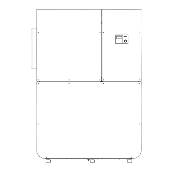
INSTALLATION SPECIFICATION 17.6 Connections 1 Safety valve 2 Condensate drain 3 Heating circuit flow 4 Heating circuit return 5 DHW return 6 DHW flow 7 Air entry 8 Air discharge 9 Cable entry for electrical cables 17.7 Connection dimensions | WPL HT www.stiebel-eltron.com... -
Page 53: Commissioning Report
INSTALLATION COMMISSIONING REPORT 18. Commissioning report www.stiebel-eltron.com WPL HT|... - Page 54 INSTALLATION COMMISSIONING REPORT | WPL HT www.stiebel-eltron.com...
- Page 55 INSTALLATION COMMISSIONING REPORT www.stiebel-eltron.com WPL HT|...
-
Page 56: Guarantee / Environment And Recycling
GUARANTEE / ENVIRONMENT AND RECYCLING |WPL HT www.stiebel-eltron.com... - Page 57 NOTES www.stiebel-eltron.com WPL HT |...
- Page 58 NOTES |WPL HT www.stiebel-eltron.com...
- Page 59 NOTES www.stiebel-eltron.com WPL HT |...
Need help?
Do you have a question about the WPL 14 HT S and is the answer not in the manual?
Questions and answers