Advertisement
Copyright © 2019-2023 SubDude Audio LLC, Idaho, USA. All
Rights Reserved. Reproduction, transmission or
redistribution of this document or its contents without
written permission is prohibited.
Take your time, follow the instructions, relax, and enjoy yourself!
WARNING: Perform installation with your pinball machine turned off and unplugged from AC power.
Advertisement
Table of Contents

Related Manuals for SubDude Audio PinWoofer Sega Whitestar GTP


Summary of Contents for SubDude Audio PinWoofer Sega Whitestar GTP
- Page 1 Copyright © 2019-2023 SubDude Audio LLC, Idaho, USA. All Rights Reserved. Reproduction, transmission or redistribution of this document or its contents without written permission is prohibited. Take your time, follow the instructions, relax, and enjoy yourself! WARNING: Perform installation with your pinball machine turned off and unplugged from AC power.
- Page 2 PinWoofer Sega Whitestar GTP Amplifier Installation Instructions...
-
Page 3: Amplifier Placement
Amplifier Placement Remove the Coin Box and replace it with • the amplifier resting as shown. Use only a PinWoofer supplied Amplifier • Mounting Bracket. Aside from being more secure, it will allow you to transport your machine with the amplifier installed into the bracket. -
Page 4: Harness Routing
Harness Routing Unplug the machine from AC Power. • Anchor Point Open the Coin Door. • Remove the Playfield Glass. • Lift the Playfield and prop it up. • Remove the backglass and lower the • Speaker Panel. Slack Feed the Amplifier End of the PinWoofer •... -
Page 5: Power Connection
Power Connection • Unplug the 10-Pin Factory Connector from J10. • Plug the 10-Pin Factory Connector into the PinWoofer Power Board. • Plug the PinWoofer Harness 2- Pin Power Connector into the Power Board. • Plug the Power Board into J10. •... -
Page 6: Audio Connection
Audio Connection Ground Loop • Remove the factory speaker wire Isolator connector from header CN4. This connector is no longer used. Expander Board • Plug the Harness TRS Plug into Harness TRS Cable the Ground Loop Isolator. TRS Plug Extension •... - Page 7 Connect Backbox Speakers • Connect the BLU_BLK Speaker Wire Pairs on the PinWoofer Harness to each of the left and right terminals of your Backbox Speaker Terminals: • Connect the BLU wire to “+” Terminal • Connect the BLK wire to “-” Terminal...
- Page 8 Connect Cabinet Speaker • Definitions: SVC – Single Voice Coil DVC – Dual Voice Coil • For DVC, do not alter the factory wires present on your new Cabinet Speaker. • Connect the RED_BLK Speaker Wire Pair on the PinWoofer Harness to your Cabinet Speaker Terminals: Harness...
- Page 9 Amplifier to Harness Connections • Insert the TRS Male Plug on the amplifier end of the PinWoofer Harness into Input TRS Jack. • Plug the 6-Pin Molex Connector into the Speaker Output Header. The Connector tab locks should Power Input Jack be facing upward.
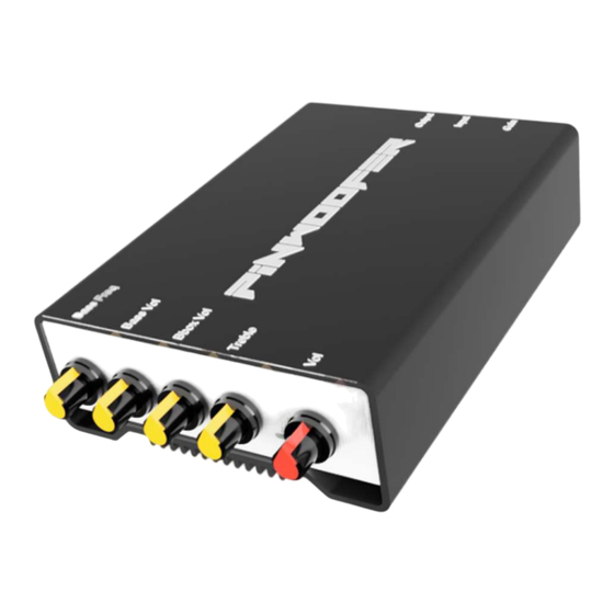
- Page 10 When first powering on your PinWoofer Amplifier, adjust the controls as shown: • “Bass Vol” set to “6 o’clock” • “Gain” set to “3 o’clock”, or about 75% clockwise Auto-Mute Disable Switch* • All other controls set to “12 o’clock” Input Gain Control Master Volume Power Input...
- Page 11 • After installation, turn the machine on and follow the below startup procedure: 1. Set the service Menu Volume (using coin door volume buttons) to 7. 2. If you are experiencing “cut-out” of the signal, increase the gain setting or increase the title menu volume. The auto-muting can be disabled, but the amplifier may pickup the noise present in the audio line.
-
Page 12: End Of Document
End of Document...
Need help?
Do you have a question about the PinWoofer Sega Whitestar GTP and is the answer not in the manual?
Questions and answers