Advertisement
Quick Links
Copyright © 2019-2022 SubDude Audio LLC, Idaho, USA. All
Rights Reserved. Reproduction, transmission or
redistribution of this document or its contents without
written permission is prohibited.
Take your time, follow the instructions, relax, and enjoy yourself!
WARNINGS: Perform installation with your pinball machine turned off and unplugged from AC power.
Advertisement

Related Manuals for SubDude Audio JJP PINWOOFER


Summary of Contents for SubDude Audio JJP PINWOOFER
- Page 1 Copyright © 2019-2022 SubDude Audio LLC, Idaho, USA. All Rights Reserved. Reproduction, transmission or redistribution of this document or its contents without written permission is prohibited. Take your time, follow the instructions, relax, and enjoy yourself! WARNINGS: Perform installation with your pinball machine turned off and unplugged from AC power.
- Page 2 DIY Amplifier Installation Instructions...
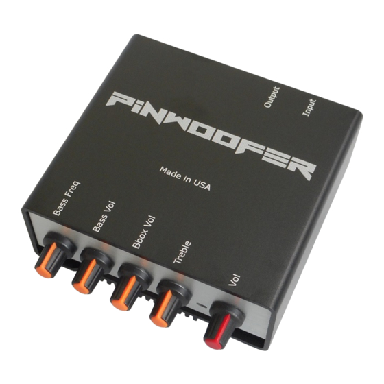
- Page 3 JJP PinWoofer Amplifier Shown is the PinWoofer JJP DIY Amplifier.
- Page 4 JJP Amplifier Card - Removal Disconnect all electrical connections on the JJP Amplifier Card: Mini-Plug in the upper right-hand corner • J104 Cabinet Speaker • J105 Left Backbox Speaker • J106 Right Backbox Speaker • Power plug YEL_BLK to ATX Power •...
- Page 5 JJP Amplifier Removal 1. Remove the six amplifier mounting screws. 2. Do no discard screws since they will be re-used to mount your DIY amplifier.
-
Page 6: Power Board
Mount PinWoofer Power Board 1. Connect the PinWoofer Power Board at location J110. If there is a already a connector populated at J110, it can be re-plugged into the PinWoofer Power Board Header (POTC). 2. It is vital to secure the ground wire at the location shown. - Page 7 JJP Power Cable Connection 1. Connect the 2-pin Power Cable to the Power Board as shown.
- Page 8 Mount Amplifier - Part 1. Secure the four screws as shown.
- Page 9 Mount Amplifier - Part 1. Secure the final two screws over the included control panel.
- Page 10 JJP – Connect Audio Mini-Plug 1. Connect the mini-plug at the lower right- hand corner of the DIY Amplifier as shown.
- Page 11 JJP – Connect Power and Speaker Lines 1. Plug the Power Connector to Vin. 2. Plug the Sub/Right/Left Speaker Lines to the appropriate header.
- Page 12 Your DIY amplifier is now ready for use.
Need help?
Do you have a question about the JJP PINWOOFER and is the answer not in the manual?
Questions and answers