Table of Contents
Advertisement
Quick Links
REFRIGERATOR
RT598*/58*
RT557*/97*
MT-12 GLOBAL (RT598)-14.05.22.indd 1
REFRIGERATOR
Basic Model : RT598* (Dispenser+CSZ)
Model Code : RT598*/58* (Dispenser+CSZ)
RT556*/96* (No Dispenser+ No CSZ)
RT557*/97* (Dispenser+No CSZ)
1. PRECAUTION
2. PRODUCT SPECIFICATIONS
3. DISASSEMBLY AND REASSEMBLY
4. TROUBLE SHOOTING
5. PCB DIAGRAM
6. WIRING DIAGRAM
7. SCHEMATIC DIAGRAM
8. REFERENCE INFORMATION
RT556*/96*
CONTENS
2014. 5. 22.
8:56
Advertisement
Table of Contents
Troubleshooting

Related Manuals for Samsung RT598 Series


Summary of Contents for Samsung RT598 Series
- Page 1 REFRIGERATOR Basic Model : RT598* (Dispenser+CSZ) Model Code : RT598*/58* (Dispenser+CSZ) RT556*/96* (No Dispenser+ No CSZ) RT557*/97* (Dispenser+No CSZ) REFRIGERATOR CONTENS 1. PRECAUTION 2. PRODUCT SPECIFICATIONS 3. DISASSEMBLY AND REASSEMBLY 4. TROUBLE SHOOTING 5. PCB DIAGRAM 6. WIRING DIAGRAM 7. SCHEMATIC DIAGRAM 8.
- Page 2 SAMSUNG ELECTRONICS Technical Service Guide Copyright ⓒ2012 All rights reserved. This service guide may not be reproduced in whole or in part in any form without written permission from the SAMSUNG ELECTRONICS Company. MT-12 GLOBAL (RT598)-14.05.22.indd 2 2014. 5. 22.
-
Page 3: Table Of Contents
Contents 1. PRECAUTIONS (SAFETY WARNINGS) ............4 2. PRODUCT SPECIFICATIONS ..............7 2-1. Model Specification ............................7 2-2. View of your FRIDGE / FREEZER ........................ 8 2-3. Model Specification ............................10 2-4. Electrical Part Specifications & Standard ....................10 2-5. Dimension (MM) ............................12 2-6. Display Design .............................. 13 3. - Page 4 Contents 5. PCB DIAGRAM ..................63 5-1. Part Layout (Main Board) ..........................63 5-2. Parts Layout (Inverter Board) ........................64 5-2. Connector Arrangement (Main Board) ...................... 66 5-3. Connector Arrangement (Main Board) .......................67 6. WIRING DIAGRAM ..................68 7. BLOCK DIAGRAM ..................69 7-1.
-
Page 5: Precautions (Safety Warnings)
1. PRECAUTIONS (SAFETY WARNINGS) ● Upon electronic Control system repair/change, make sure the set unplugged. Be ware of electric shock. ● Use rated electronic Control equipment. Make sure to check out ModeL name, Rated voltage, Rated current, Operation Temp, etc. ●... - Page 6 PRECAUTIONS (SAFETY WARNINGS) Read all instructions before repairing the product and keep to the instructions in order to prevent danger or property damage. CAUTION/WARNING SYMBOLS DISPLAYED SYMBOLS means Prohibition”. Indicates that a means Do not disassemble”. Warning danger of death or serious injury means No contact”.
- Page 7 PRECAUTIONS (SAFETY WARNINGS) Please ler users know following warnings & cautions in detail. Warning & Caution Do not allow users to store narrow and Do not allow users to store pharmaceutical Do not allow users to put bottles or kinds of lengthy bottles or foods in a small multi- products, scientific materials, etc., in the glass in the freezer.
-
Page 8: Product Specifications
2. PRODUCT SPECIFICATIONS 2-1. Model Specification SAMSUNG Electrolux IMAGE MODEL RT598* GN-515GW ETE 5107 SD Capacity 560L 515L 476L Dimension 836Ⅹ777Ⅹ1853 780Ⅹ730Ⅹ1720 798Ⅹ708Ⅹ1780 · Active Hybrid Deo Fresh · Coolselect Turbo System · Slim Water Dispenser · 515 Litre Top Mount ·... -
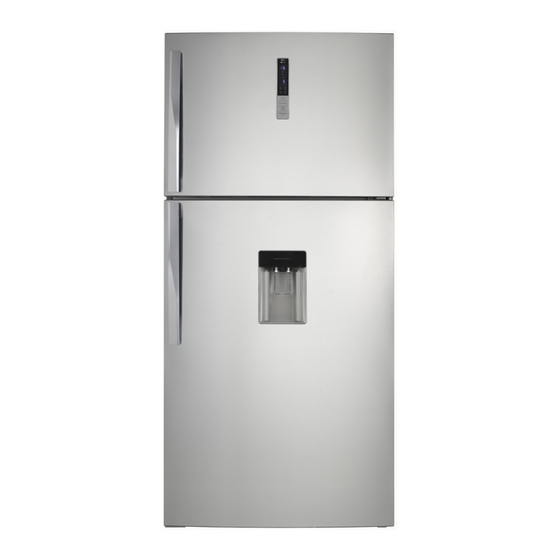
Page 9: View Of Your Fridge / Freezer
PRODUCT SPECIFICATIONS 1-3. 정전기, PL, 전압사용 관련 주의사항 2-2. View of your FRIDGE / FREEZER DISPENSER TYPE : RT557*/RT558*/RT597*/RT598* Freezer Lamp Freezer Guard Freezer Shelf Water Tank (option) Coolselect Turbo (option) GUARD MINI GUARD DISPENSER Refrigerator LAMP GUARD DISPENSER Bottle Guard SIDE LED Deodorizer VEGATABLE... - Page 10 PRODUCT SPECIFICATIONS NO DISPENSER TYPE : RT556*/RT596* Freezer Lamp Freezer Guard Freezer Shelf Water Tank (option) Coolselect Turbo (option) GUARD MINI GUARD DISPENSER Refrigerator LAMP GUARD DISPENSER Bottle Guard SIDE LED Deodorizer VEGATABLE DRAWER (option) MT-12 GLOBAL (RT598)-14.05.22.indd 9 2014. 5. 22. 8:56...
-
Page 11: Model Specification
PRODUCT SPECIFICATIONS 2-3. Model Specification Model RT598* RT597* RT596* RT558* RT557* RT556* Type TMF 2 Door TMF 2 Door Temperature control Electronic Total Net Capacity Freezer Refrigerator 836Ⅹ777Ⅹ1853 836Ⅹ777Ⅹ1788 Dimension (WⅩDⅩH) Package 896Ⅹ776Ⅹ1981 896Ⅹ776Ⅹ1916 Cabinet CYCLO-PENTANE CYCLO-PENTANE Foam insulation Door CYCLO-PENTANE CYCLO-PENTANE Cabinet... - Page 12 PRODUCT SPECIFICATIONS MODEL RT55*, RT59* OFF (℃) Type Temperature Selection ON (℃) -14 ℃ -12 ℃ -16 ℃ Freezer F-Sensor -19 ℃ -17 ℃ -21 ℃ -24 ℃ -22 ℃ -26 ℃ Type Temperature Selection ON (℃) OFF (℃) 7 ℃ 5℃...
-
Page 13: Dimension (Mm)
PRODUCT SPECIFICATIONS 2-5. Dimension (MM) MODEL RT59 1188 1853 RT55 1079 1788 MT-12 GLOBAL (RT598)-14.05.22.indd 12 2014. 5. 22. 8:56... -
Page 14: Display Design
PRODUCT SPECIFICATIONS 2-6. Display Design MT-12 GLOBAL (RT598)-14.05.22.indd 13 2014. 5. 22. 8:56... -
Page 15: Disassembly & Reassembly
3. DISASSEMBLY & REASSEMBLY 3-1. Precautions • Unplug the refrigerator before cleaning and making repairs. • Do not dissemble or repair the refrigerator by yourself. - You run risk of causing a fire, malfunction and/or personal injury. • Remove any foreign matter or dust from the power plug pins. - Otherwise there is a risk of fire. -
Page 16: Assy Door
DISASSEMBLY & REASSEMBLY 1-2. 안전 및 설치시 주의사항 3-2. Assy Door PART NAME DESCRIPTION FIGURE 1. With the door closed, remove the Cap-Hinge Upp. (Like the picture, take off the Cap-Hinge Upp along the arrow) 2. Disconnect the connector of wires. Removing the Freezer Door 3. - Page 17 DISASSEMBLY & REASSEMBLY PART NAME DESCRIPTION FIGURE 1. Open the Refrigerator door. 2. Remove hinge screws by turnig to counterclockwise, and then take off the Removing Hinge-Mid. the Refrigerator Door 3. Remove the door from the low hinge by carefully lifting the door. Take care when removing the door to ensure that it does not fall on you.
- Page 18 DISASSEMBLY & REASSEMBLY PART NAME DESCRIPTION FIGURE 1. Remove the 2 screws of the PBA cover. INVERTER PBA 2. Disengage all housing connectors connected with Inverter PBA. 1. Remove the Inverter PBA by pulling the hook out. (Refer to the picture) MT-12 GLOBAL (RT598)-14.05.22.indd 17 2014.
- Page 19 DISASSEMBLY & REASSEMBLY PART NAME DESCRIPTION FIGURE 1. Remove the 2 screws of the PBA cover. MAIN PBA 2. Disengage all housing connectors connected with Main PBA. 1. Remove the Main PBA by pulling the hook out. (Refer to the picture) MT-12 GLOBAL (RT598)-14.05.22.indd 18 2014.
-
Page 20: Assy Door
DISASSEMBLY & REASSEMBLY 3-3. Assy Door PART NAME DESCRIPTION FIGURE 1. Pick Assy Cover-Dispenser like the picture, pull them upward. Disassembly of Dispenser Be careful not to scratch. CAUTION 1. Remove inlay film as shown. 2. Insert a flat-head screwdriver on the slot as shown,and unlock the tabs. - Page 21 DISASSEMBLY & REASSEMBLY PART NAME DESCRIPTION FIGURE 1. With the door closed, Remove the cover hinge upp screw by turning to philips head Driver. 2. With the door closed, remove the Cap-Hinge Upp. (Like the picture, take off the Cap-Hinge Upp along the arrow) Removing 3.
- Page 22 DISASSEMBLY & REASSEMBLY PART NAME DESCRIPTION FIGURE 1. Use a smal flat-head screwdriver to unlock the reed switches and pull the switches out. Fridege Door Reed S/W 2. Disconnect the connector of wires. 1. Use a smal flat-head screwdriver to unlock the reed switches and pull the switches out.
-
Page 23: Refrigerator Compartments
DISASSEMBLY & REASSEMBLY 3-4. Refrigerator Compartments PART NAME DESCRIPTION FIGURE These shelves allow the storage of larger items and pull out for easy access. Glass Shelf 1. Lift it up and pull the shelf out to the front. Drawers are designed for storage of fruits, vegetables, and deli items. -
Page 24: Refrigerator Compartments
DISASSEMBLY & REASSEMBLY 1-2. 안전 및 설치시 주의사항 3-5. Refrigerator Compartments PART NAME DESCRIPTION FIGURE 1. Remove 2 screws with philipshead driver. 2. pull the drawer out until it is removed. Coolselect Zone Drawer When disassembling, make sure the unit turned off If you want to assembly, CAUTION fellow the reverse order. - Page 25 DISASSEMBLY & REASSEMBLY PART NAME DESCRIPTION FIGURE 1. Remove the Cap-Screws. 2. Remove 1 screws with philipshead driver. 3. Turn the cover deodorizer counter clockwise to remove it. 4. Remove screw with philipshead driver. When disassembling, make sure the unit turned off If you want to assembly, CAUTION fellow the reverse order.
- Page 26 DISASSEMBLY & REASSEMBLY PART NAME DESCRIPTION FIGURE 1. After disassembling the Cover Multi, check the back. 2. Cut the EPS of Temperature Sensor area with a cutter. Cover Muliti - Temperature Sensor 3. Remove the cutted EPS. 4. Change the Temperature Sensor. 5.
-
Page 27: Freezer Compartments
DISASSEMBLY & REASSEMBLY 3-6. Freezer Compartments PART NAME DESCRIPTION FIGURE Ice cube 1. Pull the ice cube out to the front. Twist Icemaker 1. Pull the twist Icemaker out to the front. These shelves allow the storage of larger items and pull out for easy access. - Page 28 DISASSEMBLY & REASSEMBLY PART NAME DESCRIPTION FIGURE 1. Remove the Cap-Screws. 2. Remove 2 screws with philipshead driver. 3. Pull outh the air intake with long nose plier, and grip the cover edge as picture. 4. After seperate the Eva cover, Hold the corner of upper cover with hand and Pull it downward and outward.
- Page 29 DISASSEMBLY & REASSEMBLY PART NAME DESCRIPTION FIGURE 1. Disconnect wire harnesses at the top-right corner. 2. Take off the Evaporator Cover in the the Freezer. 3. Disconnect the wire connector (Heater, Thermo Fuse and Thermister) Evaporator 4. Disconnect the inlet and outlet pipe of the evaporator using a tube cutter or an oxy set.
- Page 30 DISASSEMBLY & REASSEMBLY PART NAME DESCRIPTION FIGURE 1. Disconnect EPS by both sides. Defrost heater 2. Disconnect a glass tube heater. MT-12 GLOBAL (RT598)-14.05.22.indd 29 2014. 5. 22. 8:56...
-
Page 31: Troubleshooting
4. TROUBLESHOOTING 4-1. Check-List before Trouble-Shooting 4-1-1. Test Function (Forced Operation / Forced Defrost) 1. When the Freezer and the Fridge buttons on the display panel are held down for more than 6 seconds, the Panel Display will blink at an interval of 0.5 second for 4 seconds. At this time, release both of the Freezer and the Fridge buttons and press the Freezer button to enter the Test Mode. - Page 32 TROUBLESHOOTING 2) Test Mode Description 1. Forced Operation Function 1-1) When any button is pressed once at the Test Mode, it enters into the Forced Operation. When it enters into the Test Mode, 'FF' will light up on the 7-segment LED. And, it indicates that it is in the Test Mode.
-
Page 33: Self-Diagnosis Function
TROUBLESHOOTING 4-1-2. Self-Diagnosis Function 1) Self-Diagnosis Function upon Initial Power-On 1-1) When the unit is plugged into the power, MICOM diagnoses the status of the temperature sensors in a few minutes. 1-2) If defective sensor is found after Self-Diagnosis, relevant Display LEDs will blink at an interval of 0.5 sec. and there will be no beeping sound. - Page 34 TROUBLESHOOTING ERROR Item Display (Refer to Self-Diagnosis Check List) ERROR MODE Display ✻ Self-Diagnosis Check List (7-Segment Display) Category Defect Description ERROR CODE (FREEZER LED) F - SENSOR Defects in Parts related to F-SENSOR R - SENSOR Defects in Parts related to R-SENSOR F - DEF - SENSOR Defects in Parts related to F-DEF-SENSOR EXT - SENSOR...
- Page 35 TROUBLESHOOTING ✻ Self-Diagnosis Error Description NO Error Code Item Description Trouble Shooting Connector Slipped-Out or Open-Contact, Wire The voltage between MAIN PCB CN30- F - SENSOR Cut or Short-Circuited, Abnormal Sensing "3(PNK) ↔8(YEL)" should within 4.5V~0.5V Temp (higher than +65℃ or lower than -50℃) The voltage between MMAIN PCB CN31- R - SENSOR Same as the above...
-
Page 36: Load Status Display Function
TROUBLESHOOTING 4-1-3. Load Status Display Function 1) At the normal operation, press the Freezer + Fridge buttons for 6 seconds. Then, the Freezer and Freezer Temperature Display will blink in an interval of 0.5 second for 4 seconds. 2) At this time, release the Freezer + Fridge buttons and press the Power Freeze button (it sends out "Ding Dong"... - Page 37 TROUBLESHOOTING ✻ Load Mode Check List (7-Segment Display) Category Defect Description ERROR CODE (FREEZER LED) LED On when the ambient temperature Overload Fridge Digit "e" is over 34℃ LED On when the ambient temperature Low Temperature Fridge Digit "f" is lower than 21℃ When the ambient temperature is Normal Condition Fridge Digit "e","f"...
-
Page 38: Restoration Of Previous Settings Upon Instant Power Outage
TROUBLESHOOTING 4-1-4. Restoration of Previous Settings upon Instant Power Outage 1) If the Display Panel is initialized by the instant power outage, it will cause customer inquiries. To prevent this, when the power is restored, the previous settings will be restored or reset based on the inside temperature of the unit. -
Page 39: Option Setting Function
TROUBLESHOOTING 4-1-6. Option Setting Function 1) At the normal operation, press the Freezer + Fridge buttons for 6 seconds. Then, the Freezer and Fridge Temperature Display will blink in an interval of 0.5 second for 4 sec. 2) At this time, release the Freezer + Fridge buttons and press the Fridge button (it sends out "Ding Dong" sound.) Then, it shifts to the Option Setting Mode. - Page 40 TROUBLESHOOTING Option Mode & Button Operation Description Indicating the set value of the selected item Indicating the selected item number Item Number Increase, Set Value Increase Item Number (Rotating) Decrease, MT-12 GLOBAL (RT598)-14.05.22.indd 39 2014. 5. 22. 8:56...
- Page 41 TROUBLESHOOTING ● When the Display Panel converts to the Option Setting mode, the entire Display except the Fridge as shown below Temp LED goes off. Freezer Temp Setting Fridge Temp Setting 1) For example, if you want to shift the standard temp of the Freezer compartment by -2℃, follow the steps below.
-
Page 42: Option Table
TROUBLESHOOTING 4-1-7. Option Table Note There are other option setting functions. But, it's got to do with the performance of the unit, not for repair purposes. So, they are not handled in this manual. (Except those described in this manual, do not change other values.) 1) Freezer Temp Shift Table Setting Item Freezer Temp Shift... - Page 43 TROUBLESHOOTING 2) Fridge Temp Shift Table Setting Item Fridge Temp Shift Location : Fridge Temp LED Option Item Setting Value Option Value Freezer Temp Ex) When shifting the Fridge default temp by +2.0℃ -0.5℃ -1.0℃ -1.5℃ -2.0℃ -2.5℃ -3.0℃ -3.5℃ +0.5℃...
-
Page 44: Troubleshooting Flow-Chart By Symptoms
TROUBLESHOOTING 4-2. Troubleshooting Flow-Chart by Symptoms DATA1.Temp Table Conversion Table - Temperature/MICOM PORT Voltage/Resistance SENSOR CHIP : PX41C Voltage Ω Voltage Ω Voltage Ω °C °F °C °F °C °F 4.694 153319 3.107 16419 1.153 2997 -56.2 4.677 144794 24.8 3.057 15731 105.8... -
Page 45: In Case Of Self Diagnosis Error
TROUBLESHOOTING 4-2-1. In case of self diagnosis error . Sensor error is displayed on the front display of the refrigerator. In case of a sensor error at the initial power connection, the refrigerator will not operate and repeatedly display (flash) the sensor part with the error. . - Page 46 TROUBLESHOOTING 2) External sensor error ERROR CODE Start MAIN PCB Connector CN30 is inserted properly? Connector contact defect / Reconnect EXT Sensor is DATA1. Temp Table normal? Replace Temp Sensor ** Sensor Resistance Reading Location ** EXT : Between CN30 #6 and CN30 #8 ** 0Ω...
- Page 47 TROUBLESHOOTING 3) F sensor error ERROR CODE Start MAIN PCB Connector CN30 is inserted properly? Connector contact defect / Reconnect F -Sensor is DATA1. Temp Table normal? ** Sensor Resistance Reading Location ** Replace Temp Sensor F : Between CN30 #3 and CN30 #8 ** 0Ω...
- Page 48 TROUBLESHOOTING 4) F DEF sensor error ERROR CODE Start MAIN PCB Connector CN30 is inserted properly? Connector contact defect / Reconnect F-DEF Sensor is DATA1. Temp Table normal? ** Sensor Resistance Reading Location ** Replace Temp Sensor F-DEF : Between CN30 #4 and CN30 #8 ** 0Ω...
- Page 49 TROUBLESHOOTING 5) Cool Select Zone sensor error ERROR CODE Start MAIN PCB Connector CN30 is inserted properly? Connector contact defect / Reconnect CSZ Sensor is DATA1. Temp Table normal? ** Sensor Resistance Reading Location ** Replace Temp Sensor CSZ : Between CN30 #1 and CN30 #8 ** 0Ω...
-
Page 50: When The Fan Is Not Working
TROUBLESHOOTING 4-2-2. When the fan is not working • This refrigerator uses BLDC fan motor. BLDC motor is a motor operated by DC 7-12V. • Generally, the F-FAN motor operates together when the COMP is ON. But when the ambient temperature is high and the door is opened/closed once, the operation is delayed for more than 1 minute. - Page 51 TROUBLESHOOTING C FAN ERROR Start The Compressor is Off. Run Forced Operation It reads DC7~12 between MAIN PCB GND and CN72 #8 FAN operates. Upon the initial power on, the compressor Apply power in 7 minutes after and the C-Fan operate. turning the motor off.
-
Page 52: When The Defrost Is Not Working (F Def Heater)
TROUBLESHOOTING 4-2-3. When the defrost is not working (F DEF heater) ☞ F DEF. ERROR When checking with the Self Diagnosis Start ** Heater Resistance Reading Location ** F-DEF : Resistance between CN70 #1(BLK) ↔ CN70 #5 (WHT) should be 240 Ω ± 10%. ** 0Ω... -
Page 53: When The Power Is Not Working (Inverter Pcb)
TROUBLESHOOTING 4-2-4. When the power is not working (INVERTER PCB) Model : RT5**3 - When Checking the INVERTER PCB Start refer to the Operation descriptions and "Reference" Section Caution There is AC230V or DC310V at the INVERTER PCB Power Circuit. So, be cautions When repairing the Plug in the unit The unit is plugged In? - Page 54 TROUBLESHOOTING Model : RT5**2 - When Checking the INVERTER PCB Start refer to the Operation descriptions and "Reference" Section Caution There is AC230V or DC310V at the INVERTER PCB Power Circuit. So, be cautions When repairing the Plug in the unit The unit is plugged In? unit or measuring values.
-
Page 55: When The Compressor Is Not Working (Inverter Pcb)
TROUBLESHOOTING 4-2-5. When the Compressor is not working (INVERTER PCB) Model : RT5**3 • Pre-Check "Check the compressor during the Forced Operation" 1. It takes more than 5 minutes before the compressor starts operating since it becomes the set temperature. 2. - Page 56 TROUBLESHOOTING Model : RT5**2 Start It passed 10minutes after COMP goes off. Check in 10 Min Refer to Test Function in this The Forced Operation is on. manual Freezer Sensor is normal? Forced Operation occurred? (Make sure to check after performing Forced Operation) Replace the Sensor...
-
Page 57: When The Alarm Is Generated Continuously
TROUBLESHOOTING 4-2-6. When the alarm is generated continuously Reference 1. Fridge / Freezer Door Open Alarm : It sends out an alarm sound when it passes over 2 minutes after the door is open. And, when the door remains open, it will keeps alarming every minute. 2. - Page 58 TROUBLESHOOTING ③ No Buzzer Sound This model has a buzzer affixed on the MAIN PCB.(Except Bar type LED Model) If there is no buzzer sound upon button press, Forced Operation or Door Open, disconnect MAIN PCB and check if the buzzer is damaged or there is any defective soldering. (If it is not a soldering problem, it is recommended replacing MAIN PCB due to difficulties in repairing) ✻...
-
Page 59: When The Panel Pcb Is Abnormal
TROUBLESHOOTING 4-2-7. When the panel PCB is abnormal ① When PANEL PCB does not light up or partially does Start Refer to Circuit Diagram attached in this manual and The connector at the check the circuit diagram Freezer upper hinge cover attached on the back of the is inserted properly. -
Page 60: When The Room Lamp Of The Refrigerator Is Not Working
TROUBLESHOOTING 4-2-8. When the room lamp of the refrigerator is not working When the Room Lamp is controlled with a 12V Regulator (Ex. Fridge LED LAMP) → It is used in the Fridge and Freezer Door & MICOM State Start Door MICOM Port MICOM #32... - Page 61 TROUBLESHOOTING When the Failure Condition occurs, the Compressor will immediately stop if the Compressor is running and there will be a 5 minute standby. During the 5 minute standby, RPM signals will be ignored. That is, even though the Inverter PCB receives the RPM signals, the Compressor does not work. It blinks every second and there is 2 second off at the end of each cycle.
-
Page 62: When Fridge Damper Does Not Work
TROUBLESHOOTING 4-2-9. When Fridge Damper does not work Start DAMPER is under a working condition. Forced Operation, Temp Increased Damper operates with DOOR S/W closed. DAMPER is good Door & MICOM State Door MICOM(#60) DOOR S/W is good Close Replace DOOR S/W Open Fridge temp satisfies the set temp... -
Page 63: When Csz Room Damper Does Not Work
TROUBLESHOOTING 4-2-10. When CSZ Room Damper does not work Start DAMPER is under a working condition. Forced Operation, Temp Increased CSZ temp satisfies the set temp Check Wiring & PCB MAIN Shift Set Temp [Set lower than the current temp] MAIN PCB Connector CN75 is inserted normal MICOM &... -
Page 64: Pcb Diagram
9. Buzzer Alarm : It sends out periodic alarm sounds when a button is pressed or when the door is open. 10. MICOM, Clock Generation, Software Resetting 11. Main Micom(CPU) 12. LED LAMP Control Circuitry (F/R LAMP)/(Option) 13. Inverter COMP. Signal Part This document can not be used without Samsung's authorization. MT-12 GLOBAL (RT598)-14.05.22.indd 63 2014. 5. 22. 8:57... -
Page 65: Parts Layout (Inverter Board)
5. Shunt Resistor : Compressor Current Detection Circuit. It protects the compressor from over- currents by monitoring the voltage applied to the related resistance. This document can not be used without Samsung's authorization. MT-12 GLOBAL (RT598)-14.05.22.indd 64 2014. 5. 22. - Page 66 5. Shunt Resistor : Compressor Current Detection Circuit. It protects the compressor from over- currents by monitoring the voltage applied to the related resistance. This document can not be used without Samsung's authorization. MT-12 GLOBAL (RT598)-14.05.22.indd 65 2014. 5. 22.
-
Page 67: Connector Arrangement (Main Board)
PCB DIAGRAM 5-2. Connector Arrangement (Main Board) This document can not be used without Samsung's authorization. MT-12 GLOBAL (RT598)-14.05.22.indd 66 2014. 5. 22. 8:57... -
Page 68: Connector Arrangement (Main Board)
PCB DIAGRAM 5-3. Connector Arrangement (Main Board) 1-3. 정전기, PL, 전압사용 관련 주의사항 This document can not be used without Samsung's authorization. MT-12 GLOBAL (RT598)-14.05.22.indd 67 2014. 5. 22. 8:57... -
Page 69: Wiring Diagram
Sensor&Switch Part Display Part Room Lamp Part Fan Motor Part CSZ Damper Inverter & Part SMPS Part AC Load Part R-Room Damper Part This document can not be used without Samsung's authorization. MT-12 GLOBAL (RT598)-14.05.22.indd 68 2014. 5. 22. 8:57... -
Page 70: Block Diagram
7. BLOCK DIAGRAM 7-1. BLOCK DIAGRAM This document can not be used without Samsung's authorization. MT-12 GLOBAL (RT598)-14.05.22.indd 69 2014. 5. 22. 8:57... -
Page 71: Block Diagram (Pba Inverter)
BLOCK DIAGRAM 7-2. Block Diagram (PBA Inverter) This document can not be used without Samsung's authorization. MT-12 GLOBAL (RT598)-14.05.22.indd 70 2014. 5. 22. 8:57... -
Page 72: Schematic Diagram
8. SCHEMATIC DIAGRAM 8-1. Main PCB Schematic Diagram This document can not be used without Samsung's authorization. MT-12 GLOBAL (RT598)-14.05.22.indd 71 2014. 5. 22. 8:57... -
Page 73: Block Diagram (Pba Inverter)
SCHEMATIC DIAGRAM 1-2. 안전 및 설치시 주의사항 8-2. Block Diagram (PBA Inverter) RT5**2 This document can not be used without Samsung's authorization. MT-12 GLOBAL (RT598)-14.05.22.indd 72 2014. 5. 22. 8:57... - Page 74 SCHEMATIC DIAGRAM RT5**3 This document can not be used without Samsung's authorization. MT-12 GLOBAL (RT598)-14.05.22.indd 73 2014. 5. 22. 8:57...
-
Page 75: Reference Information
9. REFERENCE INFORMATION 9-1. Nomenclatrue MT-12 GLOBAL (RT598)-14.05.22.indd 74 2014. 5. 22. 8:57... -
Page 76: Q & A
REFERENCE INFORMATION 9-2. Q & A Check Points Corrective Measures Descriptions of symptoms When the BLDC fan motor If you replace the ambient Noise (resonance) problems ● on even though the noise rotates in low RPM, The friction thermistor with a 2.7K resistance generating BLDC motors for with air is quite high and it (detecting 43℃), the BLDC fan... - Page 77 REFERENCE INFORMATION Descriptions of symptoms Check Points Corrective Measures Required clearance around the More than 5cm from the back, What is the solution for the product. 30cm from the top and 10cm from ● compressor noises? its sides. For old refrigerators What is the solution for the ●...
- Page 78 REFERENCE INFORMATION 5-?. ? Descriptions of symptoms Check Points Corrective Measures Advise customers to adjust its temperature level to one or two step Why is the fridge compartment higher. For example, when the ambient temperature is low such as in ●...
- Page 79 REFERENCE INFORMATION 5-?. ? Descriptions of symptoms Check Points Corrective Measures When the stored food sends out much smell. What can be done when it ☞ Check if there is any food sending out sustaining smells. ● sends out much smell in the Dried squid, dried laver : Hold on them Pounded garlic : Put it in fridge and the freezer an airtight container...
- Page 80 • Europe, Mid east, Africa : http://gspn1.samsungcsportal.com • Asia : http://gspn2.samsungcsportal.com • North America : http://gspn3.samsungcsportal.com - This Service Manual is a property of Samsung Electronics Co., Ltd. Any unauthorized use of Manual can be punished under applicable International or domestic law.
Need help?
Do you have a question about the RT598 Series and is the answer not in the manual?
Questions and answers