Table of Contents
Advertisement
Quick Links
Advertisement
Chapters
Table of Contents

Related Manuals for Olivetti d-Copia 3202MF


Summary of Contents for Olivetti d-Copia 3202MF
- Page 1 d-Copia3202MF/4002MF Multifunction Digital Copier SERVICE MANUAL Code: Y120250-2...
- Page 2 PUBLICATION ISSUED BY: Olivetti S.p.A. Gruppo Telecom Italia www.olivetti.com Copyright © 2023, Olivetti All rights reserved...
- Page 3 CONFIDENTIAL FOR AUTHORIZED OLIVETTI ENGINEERS ONLY. DO NOT DISTRIBUTE TO NON-AUTHORIZED PARTIES. CAUTION RISK OF EXPLOSION IF BATTERY IS REPLACED BY AN INCORRECT TYPE. DISPOSE OF USED BATTERIES ACCORDING TO THE INSTRUCTIONS. It may be illegal to dispose of this battery into the municipal waste stream. Check with your local solid waste officials for details in your area for proper disposal.
- Page 4 This page is intentionally left blank.
- Page 5 Safety precautions This booklet provides safety warnings and precautions for our service personnel to ensure the safety of their customers, their machines as well as themselves during maintenance activities. Service personnel are advised to read this booklet carefully to familiarize themselves with the warnings and precautions described here before engaging in maintenance activities.
- Page 6 Safety warnings and precautions Various symbols are used to protect our service personnel and customers from physical danger and to prevent damage to their property. These symbols are described below: High risk of serious bodily injury or death may result from insufficient attention to or incorrect compliance DANGER: with warning messages using this symbol.
- Page 7 • Always use anti-toppling and locking devices on copiers so equipped. Failure to do this may cause the copier to move unexpectedly or topple, leading to injury. • Avoid inhaling toner or developer excessively. Protect the eyes. If toner or developer is accidentally ingested, drink a lot of water to dilute it in the stomach and obtain medical attention immediately.
- Page 8 • Check that the fixing unit thermistor, heat and press rollers are clean. Dirt on them can cause abnormally high temperatures. • Do not remove the ozone filter, if any, from the copier except for routine replacement. • Do not pull on the AC power cord or connector wires on high-voltage components when removing them; always hold the plug itself.
- Page 9 CONTENTS Specifications ....................1-1 1 - 1 Specifications............................1-1 Common functions ............................ 1-1 Copy Functions ............................1-2 Printer Functions............................1-3 Scanner Functions ............................ 1-3 Option ............................... 1-4 (5-1)Document Processor (DP-7140/DP-7150/DP-7160/DP-7170) ............1-4 (5-2)Paper Feeder ........................... 1-4 (5-3)Large Capacity Feeder ........................1-4 (5-4)1,000-Sheet Finisher ........................
- Page 10 (2) Hard Disk (HD-15/16) ..........................2-20 Installation of attaching Gigabit Ethernet extension kit ................2-24 Wireless LAN interface installation ......................2-24 (5) Wireless LAN interface (IB-37/IB-38)...................... 2-27 Document table (DT-730(B)) ........................2-31 Numeric Keypad (NK-7120) ........................2-34 USB keyboard ............................2-37 (9) Card reader installation ..........................
- Page 11 3 - 8 Transfer/Separation section........................3-50 3 - 9 Fuser section ............................3-51 3 - 10 Exit/Feedshift section..........................3-53 3 - 11 Duplex conveying section ........................3-55 3 - 12 Mechanical Configuration (Optional unit)....................3-57 Document processor (DP-7140) ......................3-57 (1-1)Locations ............................
- Page 12 Precautions ............................... 4-1 Storage and handling of the drum ......................4-1 Storage of the toner container ........................4-1 How to tell a genuine Olivetti toner container .................... 4-1 4 - 2 Maintenance parts ............................. 4-2 List of maintenance parts........................... 4-2 Maintenance kits............................
- Page 13 (6-1)Detaching and reattaching the SSD ....................4-82 (6-2)Detaching and attaching the MP tray ..................... 4-85 (6-3)Detaching and reattaching the conveying unit ................4-87 (6-4)Detaching and reattaching the conveying fan motor..............4-90 (6-5)Detaching and attaching the LSU fan motor .................. 4-91 (6-6)Detaching and attaching the developer fan motor .................
- Page 14 (2-4)Horizontal black streaks ........................7-7 (2-5)Vertical streaks, band (black or color) ....................7-8 (2-6)Vertical streaks, band (white) ......................7-9 (2-7)Missing entire image (White / Black) ....................7-9 (2-8)Blurred image ..........................7-10 (2-9)Image is missing partly ........................7-10 (2-10)Entire image is light ........................7-11 (2-11)Mismatch between the original center line and output image center line (1st side) .....
- Page 15 ing variation) 7-41 (5-10)Paper skew at the trailing edge ....................7-41 (5-11)Blurred characters ........................7-41 (5-12)Offset ............................7-42 (5-13)Uneven transfer ..........................7-42 (5-14)Dirty reverse side ......................... 7-43 (5-15)Fusing failure ..........................7-43 (5-16)Trailing image ..........................7-43 Engine Factors (Image forming cause)....................7-44 (6-1)Background image is foggy.
- Page 16 (1-7)The beep sounds when the copying or printing is finished ............7-143 (1-8)When the data of the A3 or B4 size originals is transmitted, all of it is transmitted as the A4 size data . 7-143 FAX Error code ............................. 7-144 7 - 5 Send Related Errors ..........................
- Page 17 DF-7120 ..............................8-308 AK-740 ..............................8-320 MT-730(B)............................. 8-321 (10) PH-7..............................8-329 (11) FAX System 12 ............................. 8-350...
- Page 18 This page is intentionally left blank.
- Page 19 Specifications > Specifications 1 Specifications 1 - 1 Specifications (1)Common functions Items Specifications 32 ppm model 40 ppm model Type Desktop Printing Method Dry static electric transfer (laser) Paper Weight Cassette 60 to 163 g/m Multi Purpose 45 to 256 g/m (Less than A4/Letter), 209.5 g/m (Postal card) Tray...
- Page 20 Specifications > Specifications Items Specifications 32 ppm model 40 ppm model Inter Standard USB Interface Connector: 1 (Super-Speed USB) Interface Network interface: 1 (10 BASE-T/100 BASE-TX/1000 BASE-T) Hi-Speed USB: 4 (USB Flash memory slot) Option eKUIO: 2 *2 (not for user) Fax: 2 *3 Wireless LAN: 1 Operating...
- Page 21 Specifications > Specifications (3)Printer Functions Items Specifications 32 ppm model 40 ppm model Printing Speed A4/Letter 32 sheets/min 40 sheets/min A4R/Letter R 23 sheets/min 29 sheets/min A3/Ledger 17 sheets/min 21 sheets/min B4/Legal 17 sheets/min 21 sheets/min 32 sheets/min 40 sheets/min 20 sheets/min 23 sheets/min 32 sheets/min...
- Page 22 Specifications > Specifications (5)Option (5-1)Document Processor (DP-7140/DP-7150/DP-7160/DP-7170) Items Reversing auto Dual scan Product name DP-7140 DP-7150 DP-7160/DP-7170 Feed system Auto feed Auto feed Auto feed Original Sheet Sheet Sheet Original size Max: A3/Ledger (297 × 432 mm) Max: A3/Ledger (297 × 432 mm) Max: A3/Ledger (297 ×...
- Page 23 Specifications > Specifications (5-4)1,000-Sheet Finisher Items Specifications Number of Trays 1 tray Paper Size Finisher A3, A5-R, B4, B5-R, B6-R, 216×340 mm, Ledger, Legal, Statement-R Tray Executive, Oficio II, Folio, 8K, 16K-R: 500 sheets 80 g/ (When no A4-R, A4, B5, B6-R, Letter-R, Letter, 16K: 1,000 sheets stapling) Paper thickness When stapling: 90 g/m²...
- Page 24 Specifications > Specifications (5-6)Punch Unit (For 1,000-Sheet/3,000-Sheet Finisher option) Items Specifications Utilized possible paper size A3, A4-R, A4, A5-R, B4, B5-R, B5, Ledger, Letter-R, Letter, Legal, Statement-R, Folio, 8K, 16K-R, 16K Paper thickness 45 to 300 g/m Media type Plain, Preprinted, Bond, Recycled, Letterhead, Color, Thick, High Quality, Custom 1 to 8 (5-7)Mailbox (3,000-Sheet Finisher option) Items...
- Page 25 Specifications > Specifications Network FAX functions Item Specifications Hardware IBM PC-AT compatible computer Interface 10BASE-T / 100BASE-TX / 1000BASE-T Operating system Windows Vista, Windows 7, Windows 8, Windows 8.1, Windows Server 2008, Windows Server 2008 R2, Windows Server 2012, Windows Server 2016 TX resolution Ultra fine (400 ×...
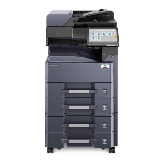
- Page 26 Specifications > Specifications 1 - 2 Part Names (1)Main unit appearance 4 5 6 11 12 14 15 19 20 1 Document Processor (option) 13 Front Cover 2 Copy Original Set Lamp 14 Cassette 1 3 Copy Original Width Guides 15 Cassette 2 4 Cleaning cloth case 16 Job Separator Lamp...
- Page 27 Specifications > Specifications 25 Paper Width Adjusting Tab 30 Right Cover 1 26 Paper Width Guides 31 MP Paper Width Guides 27 A5 Size adapter 32 MP Tray 28 Paper Length Guide 33 MP sub tray 29 Right Cover 1 lever Y120250-2 Service Manual...
- Page 28 Specifications > Specifications (2)Connectors/Interior 1 Network interface Connectors 5 Toner Container 2 USB Interface Connector 6 Toner waste box 3 USB port 7 Toner waste box (Spare) 4 Option Interface Slot Service Manual Y120250-2 1-10...
- Page 29 Specifications > Specifications (3)Optional Equipments Attached 1 Tray 1 to 7 (Tray 1 is the top tray) 6 Cassette 3 2 Tray A 7 Cassette 4 3 Tray B 8 Operation panel for Finisher 4 Job Separator Tray 9 Platen Cover 5 Finisher Tray Y120250-2 Service Manual...
- Page 30 Specifications > Specifications (4)Operation Panel Name Symb Specification [Home] key Displays the Home screen. [Data] lamp Blink when printing, sending/receiving data or accessing to HDD/SSD And lit when FAX (Send) is waiting for timer. [Attention] lamp Lights or blinks when an error occurs and a job is stopped. [Energy Saver] lamp Puts the machine into Sleep Mode.
- Page 31 Specifications > Specifications 1 - 3 Optional configuration (1) DP-7170 (1) DP-7160 (1) DP-7150 (2) MT-730(B) (1) PLATEN COVER (1) DP-7140 TYPE F (3) DF-791 (8) NK-7120 (4) DF-7120 (5) PH-7C (5) PH-7D (6) PF-791 *1 (7) PF-810 *1 *1: In case of attaching the next option, it needs to attach the metal fitting of the fall prevention : PF-791, PF-810 Y120250-2 Service Manual 1-13...
- Page 32 Specifications > Specifications Card Authentication kit (B) (13) Keyboard Holder 10 (10) FAX System 12 (14) IB-37 / IB-38 (16) DT-730(B) (15) HD-15 / HD-16 (11) IB-50 Software option (17) Internet FAX Kit(A) (18) UG-33 (19) UG-34 (12) IB-51 (20) Scan extension kit(A) (21) USB Keyboard Service Manual Y120250-2...
- Page 33 Specifications > Specifications (1)DP-7170 "Document Processor (Dual Scan with Skewed, Multifeed and Staple Detection)" DP-7160 "Document Processor (Dual Scan)" DP-7150 "Document Processor (Reverse Automatic)" DP-7140 "Document Processor (Reverse Automatic)" PLATEN COVER TYPE F "Original Cover" Automatically scans originals. Also you can perform duplex copying and split copying. For document processor operation, refer to the following: When the document processor is not used, please use the PLATEN COVER TYPE F.
- Page 34 Specifications > Specifications (12)IB-51 "Wireless Network Interface Kit" This is a wireless LAN interface card which supports the wireless LAN specifications IEEE802.11b/g/n (Max 300 Mbps) . This supports traditional protocols such as AppleTalk, Netware and so on. It also supports only the least functions in the standard utilities. The IB-51 Steup utility supports Windows OS and Mac OS X.
- Page 35 Installation > Environment 2 Installation 2 - 1 Environment Installation environment Temperature: 50 to 90.5°F (10 to 32.5 °C) Humidity: 10 to 80%RH Usable power source: 220-240V AC 6.3A Frequency fluctuation: 50Hz+/-2% or 60Hz+/-2% Installation location Avoid the place exposed direct sunlight and the strong lightning. Don't expose the photoreceptor to the direct sunlight and the strong lightning in case of the paper jam.
- Page 36 Installation > Unpacking and setting of the machine 2 - 2 Unpacking and setting of the machine Installation procedures Start Connect the power cord Unpack Execution of initial-setting operation Install the optional paper feeder Execution of mentenance item U952 Load paper Set cassette heater control Install the toner container (maintenance item U327)
- Page 37 Installation > Unpacking and setting of the machine Machine unpacking Take out the main unit and accessories from the packing case. Remove the tape and cushioning materials for packing from the main unit. 1 Skid 8 Plastic bag 15 Main unit 2 Hinge 9 Accessory box 16 Plastic bag...
- Page 38 Installation > Unpacking and setting of the machine Paper Feeder installment In case of attaching the operational paper feed, install it. Refer the setting procedure of paper feed if you want to see the detail. Main Unit Paper Feeder Loading Paper Pull out the paper storage bag.
- Page 39 Installation > Unpacking and setting of the machine Adjust the paper length guide on the paper length. Paper length guide Set the paper in the cassette Insert the cassette size plate. Push in quietly the cassette. Paper Cassette Cassette size plate Set A5 size paper in cassette.
- Page 40 Installation > Unpacking and setting of the machine Pull out the cassette. NOTE Do not pull out multiple cassette at the same time. Move the paper length guide of the cassette to the right edge. Service Manual Y120250-2...
- Page 41 Installation > Unpacking and setting of the machine Take out A5 paper feeding guide. Attach A5 paper feeding guide at the paper length guide of the cassette. Y120250-2 Service Manual...
- Page 42 Installation > Unpacking and setting of the machine Adjust the paper width guide of the cassette. Service Manual Y120250-2...
- Page 43 Installation > Unpacking and setting of the machine Set paper aligning to the right edge of cassette. IMPORTANT • Set paper that the printing surface has to be upper side. • Paper taken out from the package has to be fanned before setting them in cassette. •...
- Page 44 Installation > Unpacking and setting of the machine Insert the size display label. Insert cassette slowly to the end. Service Manual Y120250-2 2-10...
- Page 45 Installation > Unpacking and setting of the machine Toner Container installment Open the front cover. Turn the toner container vertically, beat the upper section more than five times. Reverse high and low, beat the upper section more than five times. Toner container Turn the toner container vertically, shake the upper section more than five times.
- Page 46 Installation > Unpacking and setting of the machine Shake the toner container in sideways five or six times. Toner container Push in the toner container along the guide of the main unit. IMPORTANT Push in the back till being locked. CLICK! Toner container Service Manual...
- Page 47 Installation > Unpacking and setting of the machine Installing the waste toner box Open the mouth of the waste toner box. Install the waste toner box in the main unit. Set the spare waste toner box in the main unit. Y120250-2 Service Manual 2-13...
- Page 48 Installation > Unpacking and setting of the machine The other optional equipment In case of installing the other optional equipment (finisher, fax kit, etc), install respectively. The release of the scanner lock Remove the scanner lock cover with a flat-bladed screwdriver. Reinstall the cover in the opposite direction, so both arrows face each other.
- Page 49 Installation > Unpacking and setting of the machine Fix the ground terminal of the power cord to the ground near the outlet by the screw. Wall ooutlet Power code The execution of toner installment Turn the main power switch ON. The toner install is started. CAUTION It takes about ten minutes till the state which is to be able to copy in the initial power ON.
- Page 50 Installation > Unpacking and setting of the machine [Cassette heater control setting (the execution of the maintenance mode U327)] CAUTION The cassette heater control setting is required only when the cassette heater is installed. Input "10871087" using the numeric keys and set the maintenance mode. Input "327"...
- Page 51 Installation > Unpacking and setting of the machine (1)Default setting of the copy mode. The machine in case of the factory shipment is set as following. The maintenance mode Contents Default setting in the factory shipping U250 The setting or the clear of the maintenance counts 600000 preset value 300000...
- Page 52 Installation > Unpacking and setting of the machine (2)Optional unit installation Install necessary optional units in the main unit by referring to the installation procedures. 8-273 Category Product name 40 ppm model 32 ppm model Page DP-7150 / (Document processor) ○...
- Page 53 Installation > Installing the optional parts 2 - 3 Installing the optional parts (1)SD/SDHC memory card Reading the SD/SDHC memory Card The contents of the SD/SDHC memory card are read into the main unit after turning the power on. SD/SDHC memory card installation Turn off the main unit and disconnect the power cord and all interface cables.
- Page 54 Installation > Installing the optional parts (2) Hard Disk (HD-15/16) Installation of the hard disk requires the following parts. Parts Number Parts number B2217 000 (Product) Hard Disk (HD-15) B2218 000 (Product) Hard Disk (HD-16) Procedure Turn the power off and, remove all the cables connected to the main unit and unplug the power cord. Remove 3 screws.
- Page 55 Installation > Installing the optional parts Insert hook B into the two holes A and then, raise it and slide it to the right. CAUTION When attaching, make sure not to touch the battery on the main PWB. Do not apply any force that deforms the battery holder on the main PWB. Position the hard disk on the boss of the A section and fix it with two screws B.
- Page 56 Installation > Installing the optional parts Connect the connector A and B of the cable to the hard disk. Fix the cable with the wire saddle C. CAUTION When attaching, make sure not to touch the battery on the main PWB. Do not apply any force that deforms the battery holder on the main PWB.
- Page 57 Installation > Installing the optional parts 10Align the triangle C together and pressing ① lightly in the direction of B while sliding it in the direction of A. ① 11Re-install the removed parts back to the original position. IMPORTANT • When installing the new HDD, the format will automatically start at the time of the first starting up. •...
- Page 58 Installation > Installing the optional parts (3)Installation of attaching Gigabit Ethernet extension kit Giga Ethernet extension kit installation requires the following parts. Parts Number Parts number B4805 000 (Product) Gigabit Ethernet extension kit (IB-50) (4)Wireless LAN interface installation Wireless LAN interface installation requires the following parts. Parts Number Parts number...
- Page 59 Installation > Installing the optional parts Insert the kit PWB along the OPT2 gulf, fix to two pins which detached in step 2. CAUTION • Do not touch directly to the terminal of the kit PWB. • In case of inserting the kit PWB, hold the top and bottom or the protuberance of the PWB. Gigabit ethernet board Gloove Y120250-2...
- Page 60 Installation > Installing the optional parts Insert the LAN cable into the interface connector. LAN cable Service Manual Y120250-2 2-26...
- Page 61 Installation > Installing the optional parts (5) Wireless LAN interface (IB-37/IB-38) The following parts are necessary for installing the wireless LAN interface. Parts Number Parts number B2215 000 (Product Wireless LAN interface kit (IB-37) B2216 000 (Product Wireless LAN interface kit (IB-38) Bundled item in the wireless LAN interface kit ・PWB unit: 1 pc Turn the power switch off and unplug the power cord.
- Page 62 Installation > Installing the optional parts Remove the screw (a) from the cover (c) Release the ribs (2 positions) with the flathead screwdriver (b). Remove the cover (a) in the direction of the arrow. Twist the (b) section of the cover (a) to the front side and remove it by pulling it to the left. Service Manual Y120250-2 2-28...
- Page 63 Installation > Installing the optional parts Connect the connector (b) to the Wireless network PWB (a). Install the Wireless network PWB (a) to the main unit. Slide the cover (a) to the right from the rear side of the main unit and reattach it. Y120250-2 Service Manual 2-29...
- Page 64 Installation > Installing the optional parts 10Reattach the cover (b) to the original position and fix it with the screw (a). Service Manual Y120250-2 2-30...
- Page 65 Installation > Installing the optional parts (6)Document table (DT-730(B)) Document table installation requires the following parts. Parts Number Parts number B4571 000 (Product) Document table (DT-730(B)) Bundled parts of Document table Tray stay1 pc Tray mounting plate1 pc Tray cover1 pc Tray lower cover1 pc Tray fixing plate1 pc Sheet2 pc...
- Page 66 Installation > Installing the optional parts Insert the mounting plate into the tray stay by using two screws. Screw Tray mounting Tray stay Screw plate Attach the tray cover to the tray stay by using four screws. Screws Screws Tray cover Tray stay Attach the tray lower cover.
- Page 67 Installation > Installing the optional parts Fix the tray lower cover by using two pins. Tray lower cover Screw Screw Affix the two sheets on the document table. Sheet Sheet Document table Y120250-2 Service Manual 2-33...
- Page 68 Installation > Installing the optional parts (7)Numeric Keypad (NK-7120) Numeric Keypad 1 pc NK-7120 (B3710 000) Accessories • Numeric Keypad 1 pc • Numeric Keypad cover 1 pc • Screw (M3x8) 2 pc • Label 1 pc Turn the power switch off and disconnect the power plug. Remove the screw (b) (M3x8) from the operation unit (a).
- Page 69 Installation > Installing the optional parts Connect the connector (b) of the numeric keypad (a) to the connector (c) of the operation unit. Latch two hooks (b) on the cut-out (c) of the operation unit, and then attach the numeric keypad (a) with two screws (d) (M3x8).
- Page 70 Installation > Installing the optional parts Affix the label (b) on the numeric keypad (a). IMPORTANT Check if shape of label and position are same and affix the label. Service Manual Y120250-2 2-36...
- Page 71 Installation > Installing the optional parts (8)USB keyboard USB keyboard installation requires the following parts. Parts Number Parts number B3333 000 (Product) - Keyboard holder 10 USB keyboard Bundled parts of Keyboard holder 10 Upper keyboard mounting bracket1 pc Lower keyboard mounting bracket1 pc Upper keyboard cover1 pc Lower keyboard cover1 pc Upper lid1 pc...
- Page 72 Installation > Installing the optional parts Attach the upper keyboard mounting bracket onto the lower keyboard mounting bracket by using the four screws. IMPORTANT Align the location of the mark A and attach. Screw Screw Screw Screw Upper keyboard mounting bracket Lower keyboard mounting bracket Raise the operation panel.
- Page 73 Installation > Installing the optional parts Remove one screw, slide the keyboard cover in the direction of the arrow and remove it. Keyboard cover Screw Latch two hooks of the lower keyboard mounting on two apertures. Attach the lower keyboard mounting bracket by using two screws A(M4x8). Fix the arms of the lower keyboard mounting bracket by using two screws B(M4x14).
- Page 74 Installation > Installing the optional parts 11Insert two protrusions of the lower cover C, two hooks A and three hooks B into the cut-out of the lower cover B, the aperture and the protrusion of the upper keyboard mounting bracket. Upper keyboard Lower cover B mounting bracket...
- Page 75 Installation > Installing the optional parts 14Insert the upper keyboard cover into the upper keyboard mounting plate and attach it. 15Put two hooks and the protrusion together and attach the upper cover to the lower keyboard mounting bracket. 16Fix the upper cover to the lower keyboard mounting bracket by using the one screw. Screw Upper cover Protrusion...
- Page 76 Installation > Installing the optional parts 19Connect the USB cable with the USB connector on the main unit. USB cable USB connector Keyboard hook-and-loop fasteners 20Reattach the removed card reader cover and the below operation panel cover in the original position. Service Manual Y120250-2 2-42...
- Page 77 Installation > Installing the optional parts (9) Card reader installation ID card reader installation requires the following parts. After checking to press the power source key, put out the power source lamp and memory lamp, turn the main power switch OFF and unplug the power plug. Detach the screw (b) and remove the operation panel lower cover.
- Page 78 Installation > Installing the optional parts Connect the winding portion. winding portion winding portion card reader USB cable card reader holder Pull the card reader cover (a) in the right side and attach it. Affix the card label (b). Reattach the operation panel lower cover in the original position. Card reader cover Service Manual Y120250-2...
- Page 79 Installation > Installing the optional parts Activating Card Authentication IMPORTANT Need the License Key in the introduction procedure. If access the designated website of your dealer or service representative, and register the "Machine No." indicated on your machine and the "Product ID" indicated on the License Certificate.
- Page 80 Installation > Installing the optional parts (10)Installing Cassette heater Cassette heater installation requires the following parts. Parts Number Parts number AVGR32268Q (Product) PARTS HEATER DEHUMIDIFIER 240 SET SP (10-1)Installing Cassette heater Remove three (3) screws (a) and remove the rear upper cover (b). Service Manual Y120250-2 2-46...
- Page 81 Installation > Installing the optional parts Remove four (4) screws (a) and remove rear lower cover (b). Remove the screw (a) and detach the power supply box cover. Disconnect the connector (a) from the wire saddle (b) and remove the wire from the power supply box. Y120250-2 Service Manual 2-47...
- Page 82 Installation > Installing the optional parts Disconnect three (3) connectors. Release the wire saddle and remove the binding band with snaps. Disconnect the connector and release the wire from the wire saddle. Disconnect five (5) connectors (a, b, c, d, e) and pull the wire out from the power source box and release the wire saddle (f).
- Page 83 Installation > Installing the optional parts Remove four (4) screws and remove the power source box. 10Remove four (4) screws and remove the inlet attachment plate. 11Pull out the cassettes. 12Insert the connector in the hole and put the heater wire through the rear side. Y120250-2 Service Manual 2-49...
- Page 84 Installation > Installing the optional parts 13Install the cassette heater with two (2) screws. 14Fix the heater wire with two (2) wire saddle. 15Insert the cassettes. 16Connect the heater wire and fix it with the wire saddle. Service Manual Y120250-2 2-50...
- Page 85 Installation > Installing the optional parts 17Attach the inlet attachment plate with four (4) screws. 18Connect three (3) connectors and attach the power source box. 19Attach the power source box with four (4) screws. 20Fix the wire with the wire saddle. Y120250-2 Service Manual 2-51...
- Page 86 Installation > Installing the optional parts 21Attach the binding band of the fan motor wire. 22Fix the wire saddle and connect the connector. 23Connect three (3) connectors. 24Attach the binding band and fix the wire saddle and connect the connector. Service Manual Y120250-2 2-52...
- Page 87 Installation > Installing the optional parts 25Fix the wire saddle. 26Connect five (5) connectors and attach the wire saddle. 27Attach the power supply box cover (a) with the screw. 28Attach the rear lower cover (a) with four (4) screws. Y120250-2 Service Manual 2-53...
- Page 88 Installation > Installing the optional parts 29Attach the rear upper cover (a) with three (3) screws. (10-2)Installing the PF-791 cassette heater Pull out two (2) drawers. Open two (2) wire saddles. Install the cassette heater by putting the connector of the cassette hater through the hole of the back side plate.
- Page 89 Installation > Installing the optional parts Fix the cassette heater to the frame with two (2) screws. Fix the cassette heater wire with two (2) wire saddle. Insert two (2) drawers. Y120250-2 Service Manual 2-55...
- Page 90 Installation > Installing the optional parts Remove two screws (a) and remove the rear cover (b). Connect the connector of the cassette heater and fix it with the wire saddle. Attach the binding band and fix the cassette heater wire. Cut off the excess binding band with nipper.
- Page 91 Installation > Installing the optional parts 11Attach the rear cover with two (2) screws. (10-3)Installing the PF-810 cassette heater Pull out both left and right of the cassettes and pull out the conveying unit. Open three (3) wire saddles. Y120250-2 Service Manual 2-57...
- Page 92 Installation > Installing the optional parts Connect the connector of the cassette heater and install the cassette heater. Fix the cassette heater to the frame with two (2) screws (a). Fix the cassette heater wire with three (3) wire saddles. Service Manual Y120250-2 2-58...
- Page 93 Installation > Installing the optional parts Attach the heater cover (b) with a screw (a). Insert the conveying unit (a) and insert both left and right of the cassettes. (10-4)The change of Cassette heater switch Remove the cover of the cassette heater switch. Change the cassette heater switch.
- Page 94 Installation > About Optional Applications Attach the removed switch cover. Cassette heater switch Switch cover IMPORTANT In case of changing the switch, execute the maintenance mode U0327 after inputing the power source. Input "10871087" using the numeric keys and set the maintenance mode. Input "327"...
- Page 95 Installation > About Optional Applications Starting Use of an Application Use the procedure below to start using an application. Select [System Menu/Counter] key > [System/Network] > [Optional Function]. NOTE If the user authentication screen appears, enter your login user name and login password and select [Login]. Login with administrator privileges.
- Page 96 Installation > Initializing procedures after installing the FAX system 2 - 5 Initializing procedures after installing the FAX system Connect the power plug of the main unit to the outlet and turn the power on. Input "10871087" using the numeric keys to enter the maintenance mode. Input "600"...
- Page 97 Machine Design > Mechanical Configuration 3 Machine Design 3 - 1 Mechanical Configuration (1)Cross-section view Light path Paper path Paper path (option) 1 Cassette 1 7 Transfer/ Separate section 13 Exit section 2 Cassette 1 paper feed section 8 Charger roller unit 14 Dual conveying section 3 Cassette 2 9 Drum unit...
- Page 98 Machine Design > PWB description 3 - 2 PWB description (1)Main PWB (1-1)PWB photograph (1-2)Connector position YC24 YC29 YC31 YC23 YC20 YC18 YC32 YC12 YC17 YC22 YC15 YC11 YC13 YC16 YC10 YC33 YC14 YC19 Service Manual Y120250-2...
- Page 99 Machine Design > PWB description (1-3)Connector lists Destination • YC4: SD card • YC5: Ethernet • YC6: USB Device • YC7: USB Host • YC8: eKUIO relay PWB • YC9: eKUIO relay PWB • YC10: USB PWB • YC11: USB PWB •...
- Page 100 Machine Design > PWB description Connector Pin Signal Voltage Description TD3- Differential Ethernet send and receive signal(N) TD4+ Differential Ethernet send and receive signal(P) TD4- Differential Ethernet send and receive signal(N) YWLED_K DC0V/OPEN Yellow LED cathode YWLED_A DC3.3V Yellow LED anode GRLED_K DC0V/OPEN Green LED cathode...
- Page 101 Machine Design > PWB description Connector Pin Signal Voltage Description LP-1 LockPin(1) Lock terminal LP-2 LockPin(2) Lock terminal YC10 +5.0V13_USBHUB DC5V DC5V power output +5.0V13_USBHUB DC5V DC5V power output +5.0V13_USBHUB DC5V DC5V power output YC11 VBUS DC5V DC5V power output Differential USB data signal(N) Differential...
- Page 102 Machine Design > PWB description Connector Pin Signal Voltage Description LED_ATTENTION DC0V/3.3V ATTENTION LED control signal B10 LED_PROCESSING DC0V/3.3V PROCESSING LED control signal AUDIO Analog Audio signal B12 C2P_WKUP DC0V/3.3V Panel return signal B13 GND B14 NIRQ DC0V/1.8V NFC interrupt signal B15 I2C_SDA_NFC DC0V/3.3V (pulse) I2C address / data signal...
- Page 103 Machine Design > PWB description Connector Pin Signal Voltage Description EUSS_INT0 DC0V/3.3V EUSS Video communication Success notification EUSS_CS0 EUSS Scan 5.0V4 DC5V DC5V power output 5.0V4 DC5V DC5V power output LP-1 LockPin(1) Lock terminal LP-2 LockPin(2) Lock terminal YC19 5V4IL_LSU DC5V Interlock interlocking Power supply 5V NC(E2C_WKUP_BGD)
- Page 104 Machine Design > PWB description Connector Pin Signal Voltage Description E2C_EUSS_SCAN_EN DC0V/3.3V EUSS Scan EN C2E_SCAN_DP_RDY DC0V/3.3V Device Ready Notification (DP) C2E_SCAN_TABLE_RDY DC0V/3.3V Read device Ready notification (main unit) (also used as write device) C2E_SCAN_OVM DC0V/3.3V Read device status notification OVM E2C_EUSS_SCAN_SDO DC0V/3.3V EUSS Scan...
- Page 105 Machine Design > PWB description Connector Pin Signal Voltage Description Differential SSD data send signal(P) Differential SSD data send signal(N) 3.3V DC3.3V DC3.3V power output 3.3V DC3.3V DC3.3V power output 3.3V DC3.3V DC3.3V power output LP-1 Lockpin(1) Lock terminal LP-2 Lockpin(2) Lock terminal YC22 SATATXDP_C2H...
- Page 106 Machine Design > PWB description Connector Pin Signal Voltage Description YC32 +5VIL DC5V DC5V power output VDATA2N Differential DATA2_N VDATA2P Differential DATA2_P VDATA1N Differential DATA1_N VDATA1P Differential DATA1_P SAMPLEN2 DC0V/3.3V P4 BK signal SAMPLEN1 DC0V/3.3V P2 KC signal OUTPEN DC0V/3.3V P0 KC signal VCONT DC0V/3.3V...
- Page 107 Machine Design > PWB description Connector Pin Signal Voltage Description +5V2 DC5V 5V power output LP-1 Lockpin(1) Lock terminal LP-2 Lockpin(2) Lock terminal LP-3 Lockpin(3) Lock terminal LP-4 Lockpin(4) Lock terminal LP-5 Lockpin(5) Lock terminal LP-6 Lockpin(6) Lock terminal LP-7 Lockpin(7) Lock terminal LP-8 Lockpin(8) Lock terminal...
- Page 108 Machine Design > PWB description (2)Engine PWB (2-1)PWB photograph (2-2)Connector position YC23 YC19 YC41 YC24 YC18 YC22 YC30 YC16 YC21 YC15 YC10 YC40 YC32 YC12 YC20 YC38 YC11 YC36 YC31 YC17 YC14 YC13 Service Manual Y120250-2 3-12...
- Page 109 Machine Design > PWB description (2-3)Connector lists Destination • YC5: Polygon motor • YC6: Fuser pressure release motor • YC7: Feedshift solenoid • YC8: Exit motor, JS paper full sensor, Paper full sensor, Exit sensor, JS paper sensor, Exit fan motor •...
- Page 110 Machine Design > PWB description Connector Pin Signal Voltage Description EMOTB Exit motor B EMOTAN Exit motor A- EMOTBN Exit motor B- 3.3VLED DC3.3V PIPower supply Ground JTRAYFULL DC0V/3.3V Upper discharge tray Paper full detection PI signal 3.3VLED DC3.3V PIPower supply Ground TRAYFULL DC0V/3.3V...
- Page 111 Machine Design > PWB description Connector Pin Signal Voltage Description TCON_LOCK DC0V/3.3V Toner container lock detection signal TCON_SET DC0V/3.3V With toner container Detection signal Ground DC5V RFID RF circuit Power supply 3.3V2 DC3.3V RFID control circuit Power supply RFID_SCL DC0V/3.3V RFID SCL Ground RFID_SDA...
- Page 112 Machine Design > PWB description Connector Pin Signal Voltage Description Ground A12 PAPEMP4 DC0V/3.3V Cassette 2 Paper loading level detection signal2 PAP1LSIZE1 DC0V/3.3V Cassette 1 Paper feed direction size detection signal1 Ground PAP1LSIZE2 DC0V/3.3V Cassette 1 Paper feed direction size detection signal2 PAP1LSIZE3 DC0V/3.3V...
- Page 113 Machine Design > PWB description Connector Pin Signal Voltage Description A12 24VF1 DC24V Not used A13 ANYREM Not used 24VF1 DC24V Clutch Power supply MIDCLREM DC0V/3.3V Lower resistration clutch remote 24VF1 Power Clutch power supply FEED2CLREM DC0V/3.3V Lower paper feed clutch remote 3.3VLED DC3.3V PIPower supply...
- Page 114 Machine Design > PWB description Connector Pin Signal Voltage Description PF_RDY DC0V/3.3V PF ready signal PF_SET DC0V/3.3V PF connection detection signal PF_PAUSE DC0V/3.3V PF pose signal 24V2_F7 DC24V Drive power supply 3.3V3_F1 DC3.3V Sensor Power supply (Monitoring target during sleep) 3.3V2 DC3.3V control circuit power supply...
- Page 115 Machine Design > PWB description Connector Pin Signal Voltage Description MK2_RKEY2 DC0V/3.3V Keyed card BUS2 MK2_RKEY1 DC0V/3.3V Keyed card BUS1 MK2_RKEY0 DC0V/3.3V Keyed card BUS0 Ground MK2_COUNT DC0V/3.3V Keyed card count signal YC30 24V2 DC24V LVU receiving power supply 24V2 DC24V LVU receiving power supply Ground...
- Page 116 Machine Design > PWB description Connector Pin Signal Voltage Description C2E_SCAN_OVM DC0V/3.3V Scan VSYNC monitor C2E_SCAN_TABLE_RDY DC0V/3.3V Scan (ASIC) communication RDY C2E_SCAN_DP_RDY DC0V/3.3V DP(ASIC) communication RDY E2C_EUSS_SCAN_EN DC0V/3.3V Scan EUSS communication EN E2C_EUSS_SCAN_TABL DC0V/3.3V Scan EUSS communication table select E_CS E2C_EUSS_SCAN_DP_C DC0V/3.3V Scan EUSS communication DP select...
- Page 117 Machine Design > PWB description Connector Pin Signal Voltage Description A10 GND Ground 3.3V3LED DC3.3V PIPower supply A12 5V2 Power Sensor Power supply A13 ORG_SENS DC0V/3.3V Original paper feed direction size detection signal A14 GND Ground A15 NC Not used A16 NC Not used DP_CLK...
- Page 118 Machine Design > PWB description (3)Operation panel PWB 1 (3-1)PWB photograph (3-2)Connector position YC12 YC10 YC11 YC13 Service Manual Y120250-2 3-22...
- Page 119 Machine Design > PWB description (3-3)Connector lists Destination • YC4: NFC PWB • YC5: Operation panel PWB 2 • YC6: Numeric keypad • YC7: Speaker • YC9: Main PWB • YC10: Touch panel • YC11: LCD • YC12: Main PWB Connector Pin Signal Voltage...
- Page 120 Machine Design > PWB description Connector Pin Signal Voltage Description +5.0V1_PANEL DC 5V DC 5V power input Ground P2C_WKUP_RDY DC 0V/3.3V Anykey return signal C2P_SCK DC 0V/3.3V(pulse) Panel clock signal P2C_SBSY DC 0V/3.3V Panel busy signal P2C_SDIR DC 0V/3.3V Panel communication direction signal A10 C2P _SDAT DC 0V/3.3V(pulse) Serial communication data signal...
- Page 121 Machine Design > PWB description Connector Pin Signal Voltage Description Not used Ground RxIN3+ Differential 1.075V/ Display data signal 1.425V RxIN3- Differential 1.075V/ Display data signal 1.425V Ground RxINCK+ Differential 1.075V/ Display data signal 1.425V RxINCK- Differential 1.075V/ Display data signal 1.425V Ground RxIN2+...
- Page 122 Machine Design > PWB description (4)Power supply PWB (4-1)PWB photograph (4-2)Connector position TRA811 TRA821 (White) (Black) Service Manual Y120250-2 3-26...
- Page 123 Machine Design > PWB description (4-3)Connector lists Destination • TB1/TB2: Inlet • YC1: Main Power switch • YC2: Fuser unit (Fuser heater 1,2, Fuser thermistor, Fuser pressure release sensor) • YC3: Cassette heater • YC4: Cassette heater switch • YC5: Engine PWB •...
- Page 124 Machine Design > PWB description Connector Pin Signal Voltage Description Ground DC5V 5V0 output Ground 24V3IL DC24V Power supply for fixing heater drive circuit Ground POWEROFF DC0V/5V 24V stop control signal RELAYREM DC0V/24V Fuser relay control signal ZCROSS DC0V/3.3V(pulse) Zero cross pulse signal MHREM DC0V/3.3V Main heater control signal...
- Page 125 Machine Design > Electrical parts layout 3 - 3 Electrical parts layout (1)PWBs 18,19 20 21 12 13 Front side Inside Rear side 1.Main PWB Controls the software such as the print data processing and provides the interface with computers. 2.Engine PWB Controls printer hardware such as high voltage/bias output control, paper conveying system control, and fuser temperature control, etc.
- Page 126 Machine Design > Electrical parts layout 9.NFC PWB Antenna circuit for wireless communication. 10.Drum PWB Relays wirings from electrical components on the drum unit. Drum individual information in EEPROM storage. 11.Drum relay PWB Consists of wiring relay circuit between engine PWB and the drum unit.
- Page 127 Machine Design > Electrical parts layout Name used in service manual Name used in parts list Part No. AVGR31245D LED drive PWB PARTS PWB LED ASSY SP (PARTS MOUNT LED ASSY SP) AVGR28611N LED-F PWB LED R PWB AVGR28235H Zener PWB PARTS PWB ZENER ASSY SP AVGR31245D LED PWB...
- Page 128 Machine Design > Electrical parts layout (2)Switches and sensors Machine front Machine inner Machine rear 1.Home position sensor Detects the ISU in the home position. 2.Original size timing sensor Operates the original size sensor. 3.Original size sensor Detects the size of the original. 4.Front cover switch Detects the opening and closing of the front cover.
- Page 129 Machine Design > Electrical parts layout 12.Lift sensor 1 Detects activation of upper limit of the lift plate in the cassette 1. 13.Lift sensor 2 Detects activation of upper limit of the lift plate in the cassette 2. 14.Conveying sensor 1 Detects a paper misfeed in the vertical conveying section.
- Page 130 Machine Design > Electrical parts layout (3)Motors Machine front Machine inner Machine rear 1.Main motor Drives the paper feed section and conveying section. 2.Fuser motor Drives the fuser unit. 3.Scanner motor Drives the scanner. 4.Polygon motor Drives the polygon mirror. 5.Exit motor Drives the fuser section and exit section.
- Page 131 Machine Design > Electrical parts layout 12.Developer motor Drives the developer unit. 13.Conveying fan motor Stabilize paper conveying after transfer. 14.Developer fan motor Cools the developer section. Y120250-2 Service Manual 3-35...
- Page 132 Machine Design > Electrical parts layout (4)Others 11,12 9,10 Machine front Machine inner Machine rear 1.Paper feed clutch 1 Controls the primary paper feed from cassette 1. 2.Paper feed clutch 2 Controls the primary paper feed from cassette 2. 3.Registration clutch Controls the secondary paper feed.
- Page 133 Machine Design > Electrical parts layout 12.Fuser thermostat 2 Prevents overheating of the heat roller. 13.Cassette heater Dehumidifies the cassette section. 14.Hard disk Storages the image data and information of job accounting mode. 15.Speaker Generates an error sound. 16.Developer clutch Control drive of the developer unit.
- Page 134 Machine Design > Paper feed/conveying section 3 - 4 Paper feed/conveying section The paper feed/conveying section consists of the paper feed unit that feeds paper from the cassette and the MP tray paper feed unit that feeds paper from the MP tray, and the paper conveying section that conveys the feed paper to the transfer/separation section.
- Page 135 Machine Design > Paper feed/conveying section Engine PWB MMOTREM YC38-3 MMOTCLK YC38-4 Main motor MMOTRDY YC38-5 MMOTDIR YC38-6 FEED1CLREM Feed YC13-1 clutch 1 Lift s CAS1LIFTLIT ensor 1 YC17-B7 PAP1LSIZE1 YC14-13 Paper length PAP1LSIZE2 YC14-15 switch 1 PAP1LSIZE3 YC14-16 Paper width PAP1WSIZE YC14-17 switch 1...
- Page 136 Machine Design > Paper feed/conveying section (2) MP tray paper feed section The MP tray can contain 100 sheets. Feeding from the MP tray is performed by the rotation of the MP paper feed roller. Also, function of the MP separation pad prevents paper from multiple feeding. MP feed roller Actuator(MP paper sensor) MP paper width guide...
- Page 137 Machine Design > Paper feed/conveying section (3)Conveying section The conveying section conveys paper to the transfer/separation section as paper feeding from the cassette or MP tray, or as paper refeeding for duplex printing. Paper by feeding is conveyed by the paper feed roller to the position where the registration sensor is turned on, and then sent to the transfer/separation section by the right registration roller and left registration roller.
- Page 138 Machine Design > Drum section 3 - 5 Drum section The drum section consists of the drum, the charger roller unit, and the cleaning unit, and the drum surface is uniformly charged in preparation for formation of residual image by laser beam. After transfer is complete, toner remaining on the drum surface is chipped off with the cleaning blade and is collected to the waste toner box with the drum screw.
- Page 139 Machine Design > Drum section Engine PWB Drum relay PWB Drum PWB EEPROM Eraser MC chager output High voltage PWB Waste toner sensor Y120250-2 Service Manual 3-43...
- Page 140 Machine Design > developer section 3 - 6 developer section The developer unit consists of the developer roller that forms the magnetic brush, the developer blade and the developer screws that agitate the toner.Also, the toner sensor checks whether or not toner remains in the developer unit. developer roller developer blade Upper developer cover...
- Page 141 Machine Design > developer section Engine PWB Developer clutch High voltage Developer relay PWB Developer motor Toner sensor Toner container switch EEPROM Toner container lock switch Developer PWB Y120250-2 Service Manual 3-45...
- Page 142 Machine Design > Optical section 3 - 7 Optical section The optical section consists of the image scanner section for scanning and the laser scanner section for printing. Service Manual Y120250-2 3-46...
- Page 143 Machine Design > Optical section (1)Image scanner section The original image is illuminated by the exposure lamp and scanned by the CCD image sensor in the Image sensor PWB via the three mirrors and ISU lens, the reflected light being converted to an electrical signal.If a document processor is used, the image scanner unit stops at the position of the DP contact glass and scans sequentially one row of the image on the original in synchronization with the moving timing of the original in the sub scan direction by driving the DP.
- Page 144 Machine Design > Optical section Original Contact glass LED_PWM LED_PWM YC2-4 YC29-6 AFE_RD LED_ENABLE drive PWB YC2-5 YC29-26 AFE_WD YC29-28 LED-F PWB AFE_CLK Lens YC29-30 Mirror AFE_CS LED-R PWB YC29-32 AFE_MCLK_P image YC29-34 sensor AFE_MCLK_N YC29-35 CCD PWB Engine PWB Home position sensor SMOT1B YC34-10...
- Page 145 Machine Design > Optical section (2)Laser scanner section The charged surface of the drum is then scanned by the laser beam from the laser scanner unit. The laser beam is dispersed as the polygon motor revolves to reflect the laser beam over the drum. Various lenses and mirror are housed in the laser scanner unit, adjust the diameter of the laser beam, and focalize it at the drum surface.
- Page 146 Machine Design > Transfer/Separation section 3 - 8 Transfer/Separation section The transfer and separation section consists mainly of the transfer roller, separation electrode and drum separation claws. A high voltage generated by the high voltage PWB is applied to the transfer roller for transfer charging. Paper after transfer is separated from the drum by applying separation charging that is output from the high voltage PWB to the separation electrode.
- Page 147 Machine Design > Fuser section 3 - 9 Fuser section The paper sent from the transfer/separation section is interleaved between the heat roller and the press roller. The heat roller is heated by the fuser heater, and the toner is fused by heat and pressure and fixed onto the paper because the press roller is pressed by the fuser press spring.
- Page 148 Machine Design > Fuser section FUSERJAM YC8-11 FSRPRSEN Fuser pressur YC9-11 release sensor FPMOTREM Fuser pressur YC6-3 release motor CTHERM Fuser YC9-8 thermistor 1 Engine PWB Exit sensor Fuser FTOBJ Fuser YC9-1 heater 1 thermo stat 1 FTAMB YC9-4 THPSDA Termopile YC9-5 THPSCL...
- Page 149 Machine Design > Exit/Feedshift section 3 - 10 Exit/Feedshift section The paper exit/feedshift section consists of the conveying path which sends the paper that has passed the fuser section to the inner tray, the job separator tray or the duplex conveying section. Exit roller A Exit pulley B Actuator...
- Page 150 Machine Design > Exit/Feedshift section Engine PWB JS paper JTRYFULL full sensor YC8-7 JS paper JTRAYPAP sensor YC8-16 Paper full TRAYFULL sensor YC8-10 EXTSOLPUL YC7-1 Feed-shift EXTSOLREL solenoid YC7-3 EMOT A YC8-1 EMOT B YC8-2 Exit motor EMOT AN YC8-3 EMOT BN YC8-4 Service Manual...
- Page 151 Machine Design > Duplex conveying section 3 - 11 Duplex conveying section The duplex conveying section consists of conveying path which sends the paper sent from the exit/feedshift section to the paper feed/conveying section when duplex printing. DU conveying pulley Right cover 1 DU conveying roller B DU conveying roller A...
- Page 152 Machine Design > Duplex conveying section Engine PWB DUSENS YC15-5 sensor DUCLREM YC13-5 DU clutch Service Manual Y120250-2 3-56...
- Page 153 Machine Design > Mechanical Configuration (Optional unit) 3 - 12 Mechanical Configuration (Optional unit) (1)Document processor (DP-7140) (1-1)Locations Front side: / Inside: / Back side: 1 DP PWB Relay board for the engine PWB and the DP electric parts. 2 DP top cover switch Shutting off the 24V power supply when the top cover open.
- Page 154 Machine Design > Mechanical Configuration (Optional unit) (1-2)Part name table Name used in service manual Name used in parts list Part. No. AVGR31318H 1 DP PWB PARTS PWB DRIVER ASSY SP AVGR02141X 2 DP top cover switch INTER LOCK SWITCH AVGR14723X 3 DP open/close sensor PARTS SENSOR OPT SP...
- Page 155 Machine Design > Mechanical Configuration (Optional unit) (2)Document processor (DP-7150) (2-1)Locations Front side: / Inside: / Back side: 1 DP PWB Relay board for the engine PWB and the DP electric parts. 2 DP top cover switch Shutting off the 24V power supply when the top cover open. 3 DP open/close sensor Detecting the opening and closing of the document processor.
- Page 156 Machine Design > Mechanical Configuration (Optional unit) (2-2)Part name table Name used in service manual Name used in parts list Part. No. AVGR31345F 1 DP PWB PARTS PWB DRIVER ASSY SP AVGR02141X 2 Right cover switch INTER LOCK SWITCH AVGR24752X 3 DP open/close sensor PARTS SENSOR OPT.
- Page 157 Machine Design > Mechanical Configuration (Optional unit) (3)Document processor (DP-7160) (3-1)Locations 2 17 Front side: / Inside: / Back side: 1 DP PWB Relay board for the engine PWB and the DP electric parts. 2 DP top cover switch Shutting off the 24V power supply when the top cover open. 3 DP open/close sensor Detecting the opening and closing of the document processor.
- Page 158 Machine Design > Mechanical Configuration (Optional unit) 19 DP conveying motor Driving the original conveying section in the document processor 20 DP exit motor Driving the original exit section in the document processor. 21 DP drive fan Cooling the document processor drive section. 22 DP CIS fan Cooling the CIS PWB in the document processor.
- Page 159 Machine Design > Mechanical Configuration (Optional unit) (4)Document processor (DP-7170) (4-1)Locations 2 17 1 1 3 3 1 1 3 3 3 3 3 3 Front side: / Inside: / Back side: 1 DP PWB Relay board for the engine PWB and the DP electric parts. 2 DP top cover switch Shutting off the 24V power supply when the top cover open.
- Page 160 Machine Design > Mechanical Configuration (Optional unit) 19 DP conveying motor Driving the original conveying section in the document processor 20 DP exit motor Driving the original exit section in the document processor. 21 DP drive fan Cooling the document processor drive section. 22 DP CIS fan Cooling the CIS PWB in the document processor.
- Page 161 Machine Design > Mechanical Configuration (Optional unit) Name used in service manual Name used in parts list Part. No. AVGR03561D 26 DP flip-up sensor emission SENSOR A,SEPARATION AVGR16133U 27 DP flip-up sensor reception PARTS SENSOR OPT SP Y120250-2 Service Manual 3-65...
- Page 162 Machine Design > Mechanical Configuration (Optional unit) (5)Paper feeder (PF-791) Machine front Machine inside Machine rear 1. PF main PWB (PFMPWB) ....Controls electrical components in the paper feeder and serial communica- tions with the machine. 2. Right cover 3 switch (RC3SW)....Breaks the safety circuit when right cover 3 is opened. 3.
- Page 163 Machine Design > Mechanical Configuration (Optional unit) (6) Paper feeder (PF-791) (6-1)PWB and sensors Machine front Machine inside Machine rear 1. PF main PWB (PFMPWB) ....Controls electrical parts. 2. PF paper conveying cover switch (PFPCCSW) .......... Breaks the safety circuit when PF paper conveying cover is opened, and resets paper jam detection.
- Page 164 Machine Design > Mechanical Configuration (Optional unit) 19. PF paper conveying unit switch (PFPCUSW) .......... Detects the presence of PF paper conveying unit. (6-2)Motors and others Machine front Machine inside Machine rear 1. PF paper feed motor (PFPFM)....Drives the paper feeder. 2.
- Page 165 Machine Design > Mechanical Configuration (Optional unit) (7)3000-sheet Finisher (DF-791) (7-1)PWBs Machine front Machine inside Machine rear 1. DF main PWB (DFMPWB) ....Controls electrical components. 2. Staple relay PWB (STRPWB) ....Relay the staple unit control signal. Y120250-2 Service Manual 3-69...
- Page 166 Machine Design > Mechanical Configuration (Optional unit) (7-2)Switches and sensors 18,19 14,15 Machine front Machine inside Machine rear 1. DF paper entrance sensor (DFPES) ..Detects a paper misfeed in the entrance section. 2. DF middle sensor (DFMES) ....Detects a paper misfeed in the conveying section. 3.
- Page 167 Machine Design > Mechanical Configuration (Optional unit) 11. DF tray sensor 3 (DFTS3)..... Detects the exit tray reaching the middle position. 12. DF tray sensor 4 (DFTS4)..... Detects the exit tray reaching the lower limit. 13. DF slide sensor (DFSLS) ...... Detects the slide position of the staple unit. 14.
- Page 168 Machine Design > Mechanical Configuration (Optional unit) (7-3)Motors 11,12 Machine front Machine inside Machine rear 1. DF paper entrance motor (DFPEM) ..Drives the paper entrance roller. 2. DF middle motor (DFMM) ..... Drives the middle roller. 3. DF paddle motor (DFPDM) ....Drives the paddle. 4.
- Page 169 Machine Design > Mechanical Configuration (Optional unit) (7-4)Solenoids and clutch Machine front Machine inside Machine rear 1. DF feedshift solenoid 1 (DFDRSOL)..Operates feedshift guide 1. 2. DF feedshift solenoid 2 (DFFSSOL) ..Operates feedshift guide 2. 3. DF exit clutch (DFECL) ......Drives the exit roller. Y120250-2 Service Manual 3-73...
- Page 170 Machine Design > Mechanical Configuration (Optional unit) (8)1000-sheet Finisher (DF-7120) (8-1)Locations Front side: / Inside: / Back side: Service Manual Y120250-2 3-74...
- Page 171 Machine Design > Mechanical Configuration (Optional unit) 1 DF PWB Controlling the electric parts. 2 DF staple relay PWB Relaying the staple unit control signals. 3 DF front cover switch Detecting the front cover open/close. 4 DF top cover switch Detecting the top cover open/close.
- Page 172 Machine Design > Mechanical Configuration (Optional unit) Name used in service manual Name used in parts list Part. No. AVGR15645L 5 DF entry sensor PARTS SENSOR OPT. SP AVGR14723X 6 DF middle sensor PARTS SENSOR OPT SP AVGR14723X 7 DF side registration sensor 1 PARTS SENSOR OPT SP AVGR14723X 8 DF side registration sensor 2...
- Page 173 Machine Design > Mechanical Configuration (Optional unit) (9) Attachment Kit (AK-7140) Machine front Machine inside Machine rear 1. BR PWB (BRPWB) ....... Controls the paper conveying section. 2. BR conveying sensor1 (BRCS1)... Detects a paper misfeed in the bridge section. 3.
- Page 174 Machine Design > Mechanical Configuration (Optional unit) (10)Mailbox (MT-730(B)) (10-1)Locations Front side: / Inside: / Back side: 1 MT PWB Controlling electric parts of the mailbox. 2 MT cover switch Detecting the mail box cover open/close. 3 MT tray sensor 1 Detecting overflow of paper to the tray 1.
- Page 175 Machine Design > Mechanical Configuration (Optional unit) Name used in service manual Name used in parts list Part. No. AVGR00293H 3 MT tray sensor 1 SENSOR 248NL1 AVGR00293H 4 MT tray sensor 2 SENSOR 248NL1 AVGR00293H 5 MT tray sensor 3 SENSOR 248NL1 AVGR00293H 6 MT tray sensor 4...
- Page 176 Machine Design > Mechanical Configuration (Optional unit) (11)Punch unit (PH-7) (11-1)Locations Front side: / Inside: / Back side: 1 PH PWB Controlling the electric parts of the punch unit. 2 PH home position sensor Detecting home position of the PH. 3 PH pulse sensor Rotation control for PF cam.
- Page 177 Machine Design > Mechanical Configuration (Optional unit) Name used in service manual Name used in parts list Part. No. AVGR14723X 4 PH slide sensor PARTS SENSOR OPT SP AVGR03564A 5 PH dust tank full sensor SENSOR FEED B AVGR16217V 6 PH paper edge sensor 1 PARTS PWB SENSOR B ASSY SP AVGR16216Z 7 PH paper edge sensor 2...
- Page 178 Machine Design > PWB description (Optional unit) 3 - 13 PWB description (Optional unit) (1)DP PWB (DP-7140) (1-1)PWB photograph (1-2)Connector position Service Manual Y120250-2 3-82...
- Page 179 Machine Design > PWB description (Optional unit) (1-3)Connector lists Destination • YC1:Engine PWB • YC3:Top cover switgh • YC4:Original sensor, Paper feed sensor, Registration sensor, DP Open/close sensor, Feedshift sensor, CCD sensor • YC5:LED PWB • YC6:Original length sensor, Original width sensor •...
-
Page 180: Table Of Contents
Machine Design > PWB description (Optional unit) Connector Pin Signal Voltage Description TIMING_SW DC0V/3.3V Original timing detection LED REM LED control signal: On/Off POWER LED power output LS_SW_LED DC1.2V(24V) Sensor LED power output Ground LS_SW DC0V/3.3V Original length sensor: On/Off 3.3V DC3.3V DC3.3V power output... - Page 181 Machine Design > PWB description (Optional unit) (2)DP PWB (DP-7150) (2-1)PWB photograph (2-2)Connector position YC10 YC11 YC17 YC16 Y120250-2 Service Manual 3-85...
- Page 182 Machine Design > PWB description (Optional unit) (2-3)Connector lists Destination • YC3: Engine PWB • YC4: Paper feed sensor • YC5: Top cover sensor • YC6: Original length sensor, Original width sensor • YC7: Registration sensor, image sensor sensor, Open/close sensor, Lift lower limit sensor •...
- Page 183 Machine Design > PWB description (Optional unit) Connector Pin Signal Voltage Description ANODE DC3.3V DC3.3V power output Ground RGST_SW DC0V/3.3V Registration sensor: On/Off Ground image sensor_TMG_SW DC0V/3.3V image sensor sensor: On/Off +3.3V DC3.3V DC3.3V power output ANODE DC3.3V DC3.3V power output Ground DP_OPEN DC0V/3.3V...
- Page 184 Machine Design > PWB description (Optional unit) Connector Pin Signal Voltage Description (YC11) Ground R24V DC24V DC24V power output YC16 LED_REM DC0V/3.3V LED remote signal DC24V DC24V power output ANODE DC3.3V DC3.3V power output Ground SFT_HP_SW DC0V/3.3V Feedshift sensor: On/Off ANODE DC3.3V DC3.3V power output...
- Page 185 Machine Design > PWB description (Optional unit) (3)DP PWB (DP-7160/DP-7170) (3-1)PWB photograph (3-2)Connector position YC11 Y120250-2 Service Manual 3-89...
- Page 186 Machine Design > PWB description (Optional unit) (3-3)Connector lists Destination • YC1:Engine PWB • YC2:SHD PWB • :DP flip-up sensor, DP multi feed sensor, DP slant sensor • YC4:Original length sensor, Original sensor, Lift lower limit sensor, Original width sensor •...
-
Page 187: Gnd
Machine Design > PWB description (Optional unit) Connector Pin Signal Voltage Description DC24V DC24V power output Ground Ground Ground Slant SKEW_SW DC0V/DC3.3V sensor: On/Off 3.3V DC3.3V DC3.3V power output SSW_1Piece DC0V/DC3.3V SCLK DC0V/DC3.3V(Pulse) I2C communication clock signal DC0V/DC3.3V(Pulse) I2C communication data signal SSW_2Piece DC0V/DC3.3V Ground... -
Page 188: Gnd
Machine Design > PWB description (Optional unit) Connector Pin Signal Voltage Description EXIT_ANODE DC1.2V LED DC1.2V power input Ground EXIT_SW DC0V/DC3.3V Exit sensor: On/Off 3.3V DC3.3V DC3.3V power output image sensor_TMG_SW DC0V/DC3.3V image sensor timing sensor: On/Off Ground LIFT4 DC0V/DC24V(Pulse) Lift motor control signal LIFT1 DC0V/DC24V(Pulse) - Page 189 Machine Design > PWB description (Optional unit) Connector Pin Signal Voltage Description DC0V/DC3.3V(Pulse) Conveying motor PWM signal BRAKE DC0V/DC3.3V Conveying motor brake signal PGND Ground DC24V DC24V power output YC11 DC24V DC24V power output N.C. R24V DC0V/DC24V Interlock switch 24V Y120250-2 Service Manual 3-93...
- Page 190 Machine Design > PWB description (Optional unit) (4)DP relay PWB (DP-7160/DP-7170) (4-1)PWB photograph (4-2)Connector position Service Manual Y120250-2 3-94...
- Page 191 Machine Design > PWB description (Optional unit) (4-3)Connector lists Destination • YC1:Main PWB • YC2:SHD PWB Connector Pin Signal Voltage Description DP_RST_N DC 0V/3.3V DP relay PWB system reset GND(DP_CONNECTN) Detect DP relay PWB connection PCIEP_REFCLK_DP2M Differential 0V/0.8V PCIe TX data signal (P) PCIEN_REFCLK_DP2M Differential 0V/0.8V PCIe TX data signal (N)
-
Page 192: I/O Voltage Dc0V/3.3V
Machine Design > PWB description (Optional unit) Connector Pin Signal Voltage Description EUSS_DP_CS0 DC 0V/3.3V EUSS SCN chip select HTPDN Detect synchronization LOCKN RX0N Differential 1.05V/1.35V RX data signal (N) RX0P Differential 1.05V/1.35V RX data signal (P) Service Manual Y120250-2 3-96... - Page 193 Machine Design > PWB description (Optional unit) (5)PF PWB (PF-791) Y120250-2 Service Manual 3-97...
- Page 194 Machine Design > PWB description (Optional unit) Connector Signal Voltage Description Ground Ground Connected to the.interface 3.3V4 3.3 V DC 3.3 V DC power input from machine connector 3.3V0 3.3 V DC 3.3 V DC power input from machine 24V4 24 V DC 24 V DC power input from machine PF_PAUSE...
- Page 195 Machine Design > PWB description (Optional unit) Connector Signal Voltage Description 3.3V4 3.3 V DC 3.3 V DC power output to PFLS2 Ground Connected to the PF paper PFLS2 0/3.3 V DC PFLS2: On/Off sensor 2(U)/ 3.3V4 3.3 V DC 3.3 V DC power output to PFPS2(U) (L), PF lift sensor 2 and...
- Page 196 Machine Design > PWB description (Optional unit) (6)PF PWB (PF-810) YC12 YC11 Service Manual Y120250-2 3-100...
- Page 197 Machine Design > PWB description (Optional unit) Connector Signal Voltage Description PAP_R_SW1_PW 1.2 V DC 1.2 V DC power output to PFPGS1(L) Connected to Ground the PF paper PAP_R_SW1 0/3.3 V DC PFPGS1(L): On/Off gauge sensor PAP_R_SW2_PW 1.2 V DC 1.2 V DC power output to PFPGS1(U) 1 lower, PF paper gauge...
- Page 198 Machine Design > PWB description (Optional unit) Connector Signal Voltage Description Connected to R_COVER_SW 0/3.3 V DC PFPCCSW: On/Off the PF paper VFDCL 0/24 V DC PFPCCL1: On/Off conveying 24V1 24 V DC 24 V DC power output to PFPCCL1 cover switch, PF paper con- VFDSW_PW...
- Page 199 Machine Design > PWB description (Optional unit) Connector Signal Voltage Description OUT2B 0/24 V DC(pulse) PFLM2 drive control signal Connected to OUT2A 0/24 V DC(pulse) PFLM2 drive control signal the PF lift OUT1B 0/24 V DC(pulse) PFLM1 drive control signal motor 2, PF OUT1A 0/24 V DC(pulse) PFLM1 drive control signal...
- Page 200 Machine Design > PWB description (Optional unit) Connector Signal Voltage Description Connected to 24V1 24 V DC 24 V DC power output to PFPFCL1 the PF paper HFDCL1 0/24 V DC PFPCCL2: On/Off feed clutch 24V1 24 V DC 24 V DC power output to PFPCCL2 1,PF paper conveying HFDCL2...
- Page 201 Machine Design > PWB description (Optional unit) (7)DF PWB (DF-7120) (7-1)PWB photograph (7-2)Connector position YC13 YC17 YC20 YC11 YC10 YC14 YC18 YC19 YC16 Y120250-2 Service Manual 3-105...
-
Page 202: Idc0V/3.3V
Machine Design > PWB description (Optional unit) (7-3)Connector lists Destination • YC3: Image Drive PWB • YC4: Front cover sensor, Top cover sensor • YC5: Image Drive PWB • YC6: PH PWB • YC7: PH PWB • YV8: Exit motor, Slide motor, Exit release motor, Paper entry motor, Middle motor •... -
Page 203: Idc0V To 3.3V
Machine Design > PWB description (Optional unit) Connector Pin Signal Voltage Description PU DI DC0V/3.3V Serial communication data signal input PU DO DC0V/3.3V Serial communication data signal output Ground 24V2 DC24V DC24V power output EJECT MOT 2B DC0V/24V(pulse) Exit motor control signal EJECT MOT 1B DC0V/24V(pulse) Exit motor control signal... - Page 204 Machine Design > PWB description (Optional unit) Connector Pin Signal Voltage Description READY DC0V/3.3V Staple unit READY signal DC5V DC5V power output DC0V/3.3V Staple unit HP signal YC11 TRY MOT OUT2 DC0V/24V(pulse) Tray motor control signal TRY MOT OUT1 DC0V/24V(pulse) Tray motor control signal YC16 MTRY U SENS K...
- Page 205 Machine Design > PWB description (Optional unit) Connector Pin Signal Voltage Description B12 ADJUST SENS SIG DC0V/3.3V Adjustment sensor: On/Off B13 STP MOV SENS A DC5V DC5V power output B14 GND Ground B15 STP MOV SENS SIG DC0V/3.3V Slide sensor: On/Off Y120250-2 Service Manual 3-109...
- Page 206 Machine Design > PWB description (Optional unit) (8)DF PWB (DF-791) YC18 YC12 YC17 YC16 YC23 Connector Signal Voltage DescrIption 24 V DC 24V1 24 V DC power output to DFFCSW Connected to 0/24 V DC FRONT COV SIG DFFCSW: On/Off the DF front 24 V DC EJECT COV SOURCE...
- Page 207 Machine Design > PWB description (Optional unit) Connector Signal Voltage DescrIption Ground Connected to Ground machine 24 V DC 24V1 24 V DC power input from Machine 24 V DC 24V1 24 V DC power input from Machine Ground Connected to Ground the mailbox Ground...
- Page 208 Machine Design > PWB description (Optional unit) Connector Signal Voltage DescrIption Connected to 0/24 V DC(pulse) ST MOV MOT 1B DFSLM control signal the DF Staple 0/24 V DC(pulse) ST MOV MOT 2A DFSLM control signal motor, DF exit 0/24 V DC(pulse) ST MOV MOT 1A DFSLM control signal motor,DF...
- Page 209 Machine Design > PWB description (Optional unit) Connector Signal Voltage DescrIption Connected to 0/24 V DC(pulse) PADDLE MOT 1B DFPDM control signal the DF paddle 0/24 V DC(pulse) PADDLE MOT 2A DFPDM control signal motor and DF 0/24 V DC(pulse) PADDLE MOT 1A DFPDM control signal side registra-...
- Page 210 Machine Design > PWB description (Optional unit) Connector Signal Voltage DescrIption Connected to 0/24 V DC DFTM control signal the DF tray 0/24 V DC(pulse) Clock signal motor 0/24 V DC ENABLE DFTM control signal Ground 24 V DC 24V2 24 V DC power output to DFTM 3.3 V DC DRM SENS A...
- Page 211 Machine Design > PWB description (Optional unit) Connector Signal Voltage DescrIption Connected to Ground the DF tray 0/3.3 V DC MTRY HP1 SENS SIG DFTS1: On/Off sensor 1,2,DF 3.3 V DC STAPLE SENS A 3.3 V DC power output to DFSLS slide Ground sensor,DF...
- Page 212 Machine Design > PWB description (Optional unit) Connector Signal Voltage DescrIption Ground 0/3.3 V DC MTRY BF SENS SIG DFTS5: On/Off 3.3 V DC MTRY FULL SENS A 3.3 V DC power output to DFTS4 Ground 0/3.3 V DC MTRY FULL SENS SIG DFTS4: On/Off 3.3 V DC SFT RELS SENS A...
- Page 213 Machine Design > PWB description (Optional unit) (9)MT PWB (MT-730(B)) (9-1)PWB photograph (9-2)Connector position Y120250-2 Service Manual 3-117...
- Page 214 Machine Design > PWB description (Optional unit) (9-3)Connector lists Destination • YC1: MT tray sensor 1/2/3, MT tray exit sensor 2 • YC2: MT tray sensor 4/5/6/7, MT tray exit sensor 1, MT home position sensor • YC3: DF main PWB •...
- Page 215 Machine Design > PWB description (Optional unit) Connector Pin Signal Voltage Description Ground DC5V DC5V power input DC24V DC24V power input DC24V DC24V power input DC0V/5V(pulse) MT serial communication data signal DC0V/5V(pulse) MT serial communication data signal SCLK DC0V/5V(pulse) MT clock signal DC0V/5V MT select signal READY...
- Page 216 Machine Design > PWB description (Optional unit) (10)BR PWB (AK-740) Connector Signal Voltage Description 24V1 24 V DC 24 V DC power input from machine Connect to 3.3V1 3.3 V DC 3.3 V DC power input from machine the machine Ground Ground COVER OPEN...
- Page 217 Machine Design > PWB description (Optional unit) Connector Signal Voltage Description COVER_OPEN 0/3.3 V DC BRECSW: On/Off Connect to Ground BRIDGE_LED_A 3.3 V DC 3.3 V DC power output to BRCS2 conveying Ground cover switch, BRIDGE_SENS 2 0/3.3 V DC BRCS2: On/Off conveying sensor 2...
- Page 218 > PWB description (Optional unit) (11)PH PWB (PH-7) (11-1)PWB photograph (11-2)Connector position YC10 YC11 Service Manual Y120250-2 3-122...
-
Page 219: Odc0V/24V
> PWB description (Optional unit) (11-3)Connector lists Destination • YC1: DF PWB • YC2: DF PWB • YC3: Slide motor • YC4: Motor • YC5: Solenoid, paper edge sensor 1, Tank full sensor • YC6: Slide sensor • YC7: Paper edge sensor 2 •... - Page 220 > PWB description (Optional unit) Connector Pin Signal Voltage Description SENS3.3V DC3.3V DC3.3V power output Ground PHADJ_HP DC0V/3.3V Slide sensor: On/Off PHPES_DET DC0V/3.3V Paper edge sensor 2: On/Off Ground SENS3.3V DC3.3V DC3.3V power output Ground PHMOT_PLS DC0V/3.3V Pulse sensor: On/Off SENS3.3V DC3.3V DC3.3V power output...
- Page 221 (4)How to tell a genuine Olivetti toner container As a means of brand protection, the Olivetti toner container utilizes an optical security technology to enable visual validation. A validation viewer is required to accomplish this. Hold the validation viewer over the left side part of the brand protection seal on the toner container.
- Page 222 Maintenance > Precautions for the maintenance 4 - 2 Maintenance parts (1)List of maintenance parts Maintenance part name Part No. Name used in service manual Name used in parts list AVGR23031X Registration cleaner PARTS CLEANER REGIST ASSY SP AVGR18255A Primary paper feed unit PARTS PRIMARY FEED ASSY SP AVGR18278H MP paper feed roller...
- Page 223 Maintenance > Maintenance parts (2)Maintenance kits Maintenance part name Part No. Name used in service manual Name used in parts list MK-7125/MAINTENANCE KIT MK-7125/MAINTENANCE KIT 1702V68NL0 (600,000sheet) Transfer roller unit TR-7125 Drum unit DK-7125 Developier unit DV-7125 Fuser unit FK-7125 Y120250-2 Service Manual...
- Page 224 Maintenance > Maintenance parts 4 - 3 Periodic maintenance procedures (CH: Check, CL: Clean, AD: Adjust, LU: Lubrication, RE: Replace) • Check the maintenance counts by the maintenance mode U901. Set up Maintenance User PM maintenance (x1000 counts) Points and cautions part/location call 1200...
- Page 225 Maintenance > Periodic maintenance procedures Exit and Duplex Section Maintenance User PM maintenance (x1000 counts) Points and cautions part/location call 1200 1800 Exit unit CL: VACUUM Rollers ,Pulleys CL: alcohol or dry cloth Guides CL: alcohol or dry cloth Image scanner section Maintenance User PM maintenance (x1000 counts)
- Page 226 Maintenance > Periodic maintenance procedures Original detection CL:Alcohol or dry cloth if there is problem. (lighting part switch and light reception part.) Replace if there are image problems Drive and other section Maintenance User PM maintenance (x1000 counts) Points and cautions part/location call 1200...
- Page 227 Maintenance > Maintenance parts replacement procedures 4 - 4 Maintenance parts replacement procedures Replacement of the maintenance kit is required after about 600,000 images. The message [Replace MK.] appears at the replacement timing. Execute maintenance mode U251 to reset the count after replacing the maintenance kit in the following procedures. (1)Paper feed section (1-1)Detaching and attaching the primary paper feed unit Pull the cassette, remove in the direction of the arrow.
- Page 228 Maintenance > Maintenance parts replacement procedures When replacing the new unit,proceed as follows: (1) Performs maintenance mode U901 (Checking copy counts by paper feed locations).(See page 6-236 ) Ppaer feed lever Primary paper feed unit (1-2)Detaching and attaching the MP paper feed roller and MP separation pad Open the right cover 1.
- Page 229 Maintenance > Maintenance parts replacement procedures While squeezing the holders inward, remove the MP paper feed roller. Holders MP paper feed roller Tilt the MP separation pad forward and then remove it upwards. Check or replace the MP paper feed roller and MP separation pad and refit all the removed parts. When replacing the new unit,proceed as follows: Performs maintenance mode U901 (Checking copy counts by paper feed locations).(See page 6-236 ) MP seperation pad...
- Page 230 Maintenance > Maintenance parts replacement procedures (1-3)Detaching and attaching the registration cleaner Open the front cover. Release the lock lever and remove the waste toner box. Lock lever Waste toner box Release the toner container lever and then remove the toner container. Toner container lever Toner container Service Manual...
- Page 231 Maintenance > Maintenance parts replacement procedures Release the lock lever. Lock lever Release the lock lever and open the developer cover. Lock lever Developer cover Set the cleaner lever up and draw the registration cleaner frontward. Check or replace the registration cleaner and refit all the removed parts. Y120250-2 Service Manual 4-11...
- Page 232 Maintenance > Maintenance parts replacement procedures Cleaner lever Registration cleaner Service Manual Y120250-2 4-12...
- Page 233 Maintenance > Maintenance parts replacement procedures (2)Developer section (2-1)Detaching and reattaching the developer unit Open the front cover. Release the lock lever and remove the waste toner box. Lock lever Waste toner box Release the toner container lever and then remove the toner container. Toner container lever Toner container Y120250-2...
- Page 234 Maintenance > Maintenance parts replacement procedures Release the lock lever. Lock lever Release the lock lever and open the developer cover. Lock lever Developer cover Release the lock lever and then remove the developer unit. Check or replace the developer unit and reattach the removed parts in the original position. Service Manual Y120250-2 4-14...
- Page 235 Maintenance > Maintenance parts replacement procedures When replacing the new unit,proceed as follows: (1)Performs maintenance mode U130 (Set Toner Install). (See page 6-88 ) (2)Execute maintenance mode U410 (Halftone automatic adjustment) (See page 6-169 ) Lock lever Developer unit Y120250-2 Service Manual 4-15...
- Page 236 Maintenance > Maintenance parts replacement procedures Precautions when installing the developer unit IMPORTANT When installing the developer unit, push the developer unit it clicks. Developer unit Service Manual Y120250-2 4-16...
- Page 237 Maintenance > Maintenance parts replacement procedures (3)Drum section (3-1)Detaching and reattaching the drum unit Open the front cover. Release the lock lever and remove the waste toner box. Lock lever Waste toner box Release the lock lever. Lock lever Y120250-2 Service Manual 4-17...
- Page 238 Maintenance > Maintenance parts replacement procedures Release the lock lever and open the developer cover. Lock lever Developer cover Open the right cover 1. Release the lock lever and then remove the drum unit. Check or replace the drum unit and refit all the removed parts. When replacing the new unit,proceed as follows: (1)Performs maintenance mode U410 (Halftone automatic adjustment) (See page 6-169 ) Lock lever...
- Page 239 Maintenance > Maintenance parts replacement procedures Precautions when installing the drum unit IMPORTANT When installing the drum unit, push the drum unit it clicks. Drum unit (3-2)Detaching and attaching the charger roller unit Remove the drum unit. (See page 4-17 ) Release the lock lever and then remove the charger roller unit.
- Page 240 Maintenance > Maintenance parts replacement procedures (4)Transfer/Separation section (4-1)Detaching and attaching the transfer roller unit Open the right cover 1. Release two lock levers and then remove the transfer roller unit. Check or replace the transfer roller unit and refit all the removed parts. When replacing the new unit,proceed as follows: 1)Performs maintenance mode U127 (Clear Transfer Roller Counter).
- Page 241 Maintenance > Maintenance parts replacement procedures (5)Fuser section (5-1)Detaching and attaching the fuser unit Open the right cover 1. Release the lock by pushing down the lock lever and then remove the fuser unit by griping the knobs. Check or replace the fuser unit and reattach the removed parts in the original position. When replacing the new unit, execute as following procedure.
- Page 242 Maintenance > Disassembly and Reassembly procedures 4 - 5 Disassembly and Reassembly procedures (1)Outer covers (1-1)Detaching and attaching the front cover Remove the cassette. Open the front cover. Front cover Unhitch the straps by squeezing the hooks inward as shown. Strap Strap Hooks...
- Page 243 Maintenance > Disassembly and Reassembly procedures Remove the front cover. Fulcrum axis Fulcrum axis Fulcrum part Fulcrum part Front cover (1-2)Detaching and attaching the rear upper cover Detach three screws. Open the top part of the rear upper cover, remove in the direction of the arrow. Screw Screw Screw...
- Page 244 Maintenance > Disassembly and Reassembly procedures (1-3)Detaching and attaching the rear lower cover Remove the rear upper cover. Detach four screws. Open the top part of the rear lower cover, remove in the direction of the arrow. Screw Screw Screw Lower rear cover Screw (1-4)Detaching and attaching the inner tray...
- Page 245 Maintenance > Disassembly and Reassembly procedures Open the top part of the rear upper cover, remove in the direction of the arrow. Screw Screw Screw Rear upper cover Detach four screws. Open the top part of the rear lower cover, remove in the direction of the arrow. Screw Screw Screw...
- Page 246 Maintenance > Disassembly and Reassembly procedures 10Remove the left lower cover. Screw Screw Screw Screw Screw Screw Left lower cover Hooks 11While pulling the A portion in the direction of the arrow, remove the inner tray. Inner tray (1-5)Detaching and attaching the front upper cover Pull the cassette forward.
- Page 247 Maintenance > Disassembly and Reassembly procedures Tilt the front upper cover forward and then unhook two hooks by taking out it upward. Projection Front upper cover Hooks (1-6)Detaching and attaching the exit rear cover Remove the screw and the exit rear cover. Exit rear cover Screw (1-7)Detaching and attaching the tray left cover...
- Page 248 Maintenance > Disassembly and Reassembly procedures Remove the tray left cover by releasing two projections. Projections Tray left cover Hooks Hooks Flat screwdriver Service Manual Y120250-2 4-28...
- Page 249 Maintenance > Disassembly and Reassembly procedures (2)Drive section (2-1)Detaching and attaching the drive unit 1 Detach three screws. Open the top part of the rear upper cover, remove in the direction of the arrow. Screw Screw Screw Rear upper cover Detach four screws.
- Page 250 Maintenance > Disassembly and Reassembly procedures Check or replace the drive unit 1 and reattach the removed parts in the original position. Engine PWB Drive unit 1 Connectors Screw Screw Screw Screw Lift motor 1 Screw IMPORTANT • When refitting the drive unit 1, checks that the position of a cam is in the A side from the judgement line.
- Page 251 Maintenance > Disassembly and Reassembly procedures (2-2)Detaching and attaching the drive unit 2 Detach three screws. Open the top part of the rear upper cover, remove in the direction of the arrow. Screw Screw Screw Rear upper cover Detach four screws. Open the top part of the rear lower cover, remove in the direction of the arrow.
- Page 252 Maintenance > Disassembly and Reassembly procedures Check or replace the drive unit 2 and reattach the removed parts in the original position. Connectors Connector Connector Drive unit 2 Drive unit 2 Screw Screws (2-3)Detaching and attaching the fuser press release motor assy Remove the rear upper cover and the rear lower cover and then the drive unit 1.
- Page 253 Maintenance > Disassembly and Reassembly procedures (3)Optical section (3-1)Detaching and attaching the Laser Scanner Unit (LSU) Detach three screws. Open the top part of the rear upper cover, remove in the direction of the arrow. Screw Screw Screw Rear upper cover Detach four screws.
- Page 254 Maintenance > Disassembly and Reassembly procedures Release the lock lever and then remove the job separator tray. Lock lever Job separator tray Remove the cassette. Open the front cover. Detach six screws. Pull upwards and then release four hooks. 10Remove the left lower cover. Screw Screw Screw...
- Page 255 Maintenance > Disassembly and Reassembly procedures 11While pulling the A portion in the direction of the arrow, remove the inner tray. Inner tray 12Release two hooks and remove the temperature sensor assy. 13Remove the connector of LSU fan motor. 14Detach the screw and then remove the LSU fan motor. Temperature sensor assy Hooks...
- Page 256 Maintenance > Disassembly and Reassembly procedures 17Check or replace the laser scanner unit and refit all the removed parts. Wire saddle Connectors Screw Screw Screw Screw Laser scanner unit (3-2)Detaching and attaching the lens unit Detach two screws and then remove the scanner right cover. NOTE When installing, attach close to the contact glass.
- Page 257 Maintenance > Disassembly and Reassembly procedures Remove the contact glass by pulling rightward. Contact glass Detach five screws and then remove the lens unit cover. Screw Lens unit cover Screw Screw Screw Screw Remove the FFC and the connector. Y120250-2 Service Manual 4-37...
- Page 258 Maintenance > Disassembly and Reassembly procedures Remove four screws and then remove the lens unit. Screw Lens unit Screw Screw Screw FFCs CCD PWB Attaching the lens unit When reinstalling, fix by adjusting to the scale of a original position. When replacing, decide the fix position of lens unit by the following.
- Page 259 Maintenance > Disassembly and Reassembly procedures Check or replace the lens unit and refit all the removed parts. Lens unit (3-3)Detaching and attaching the lamp unit Detach two screws and then remove the scanner right cover. NOTE When installing, attach close to the contact glass. Scanner right cover Screw Screw...
- Page 260 Maintenance > Disassembly and Reassembly procedures Remove the contact glass by pulling rightward. Contact glass Detach two screws and then remove the scanner rear cover. Screw Scanner rear cover Screw Service Manual Y120250-2 4-40...
- Page 261 Maintenance > Disassembly and Reassembly procedures Detach two screws and remove the scanner front upper cover. Scanner front Screw upper cover Screw Peel off two sheets. Move the lamp unit to the cutting lack part. Lamp unit Sheet Sheet Remove the FFC from the connector of the lamp unit. Detach three screws and then remove the lamp unit.
- Page 262 Maintenance > Disassembly and Reassembly procedures Check or replace the lamp unit and reattach the removed parts in original position. Lamp unit Screw Screw Connector Screw Lamp unit Service Manual Y120250-2 4-42...
- Page 263 Maintenance > Disassembly and Reassembly procedures (4)Detaching and reattaching the scanner wires Follow the procedures below when the scanner wires are broken or to be replaced. (4-1)Detaching the scanner wires Detach three screws. Open the top part of the rear upper cover, remove in the direction of the arrow. Screw Screw Screw...
- Page 264 Maintenance > Disassembly and Reassembly procedures Open the front cover. Detach six screws. Pull upwards and then release four hooks. Remove the left lower cover. Screw Screw Screw Screw Screw Screw Left lower cover Hooks 10Release three hooks upwards. 11Remove the left upper cover by sliding it backward. Hooks Left upper cover 12Detach two screws and remove the scanner right cover.
- Page 265 Maintenance > Disassembly and Reassembly procedures 13Remove the right upper cover. Screw Scanner right cover Screw Right upper cover 14Detach two screws and remove the scanner rear cover. Screw Scanner rear cover Screw Y120250-2 Service Manual 4-45...
- Page 266 Maintenance > Disassembly and Reassembly procedures 15Detach two screws and remove the scanner front upper cover. Scanner front Screw upper cover Screw 16Raise the operation panel. 17Detach the screw and then remove the operation panel lower cover. Screw Operation panel lower cover Service Manual Y120250-2 4-46...
- Page 267 Maintenance > Disassembly and Reassembly procedures 18Twist the A section of card reader cover in front and remove to pull in the left direction. Card reader cover 19Detach one screw, slide the keyboard cover in the direction of the arrow and remove it. Keyboard cover Screw Y120250-2...
- Page 268 Maintenance > Disassembly and Reassembly procedures 20After lifting the protrusion, remove the scanner front cover. Scanner front cover Projection 21Slide the controller box cover in sideway, and remove it. 22Remove seven connectors and release two wire saddles. Service Manual Y120250-2 4-48...
- Page 269 Maintenance > Disassembly and Reassembly procedures 23Detach six screws and then remove the controller box. Screw Screws Connectors Screws Connectors Screw Wire saddles Controller box 24Remove the wire from the saddle of the wire guide. 25Release the hook, lift the wire guide in front and remove it. Hook Wires Saddles...
- Page 270 Maintenance > Disassembly and Reassembly procedures 26Remove FFC from the engine PWB. Engine PWB 27Remove two connectors from the engine PWB. 28Release the wires from two wire saddles. Wires Wire saddles Connectors Engine PWB Service Manual Y120250-2 4-50...
- Page 271 Maintenance > Disassembly and Reassembly procedures 29Remove the four screws and then remove the scanner unit upward. Scanner unit Screw Screw Screw Screw 30Remove the two screws. 31Remove the scanner left cover and the contact glass assy. Screw Scanner left cover Scanner unit Screw 32Peel off two sheets.
- Page 272 Maintenance > Disassembly and Reassembly procedures 34Remove the FFC from the connector of the lamp unit. Lamp unit Sheet Sheet 35Detach three screws and then remove the lamp unit. Lamp unit Screw Screw Connector Screw Lamp unit 36Remove each screw and remove front and rear wire holder plates. Service Manual Y120250-2 4-52...
- Page 273 Maintenance > Disassembly and Reassembly procedures 37Remove the mirror frame 1 from the scanner unit. Screw Screw Rear wire holder plate Front wire holder plate Mirror frame 1 38Remove the scanner wire springs from the hooks. 39Remove the scanner wires. Scanner wire (black) Scanner wire springs Scanner wire...
- Page 274 Maintenance > Disassembly and Reassembly procedures Fitting requires the following tools Two frame securing tools (P/N AVGR12740X) Two scanner wire stoppers (P/N AVGR26423A) Remove the screw and remove the scanner wire drum gear. Remove the screw at two scanner wire drums. Remove the stop ring and bush from the front of the scanner wire drum shaft.
- Page 275 Maintenance > Disassembly and Reassembly procedures Secure the scanner wires using the scanner wire stoppers. Scanner wire stoppers Three turns inward Locating Locating ball ball Scanner wire drums Four turns outward Refit the scanner wire drum shaft to the scanner unit. Insert the two frame securing tools into the positioning holes at the front and rear of the scanner unit to fix the mirror frame 2 in position.
- Page 276 Maintenance > Disassembly and Reassembly procedures 13Wind the scanner wires around the grooves in the pulleys at the left of the scanner unit ....(5) 14Hook the round terminals to the scanner wire springs....(6) Black merking Gray Black 15Remove the two scanner wire stoppers and the mirror frame securing tools. 16Move to center the portion of the locating ball in the scanner wire drum, and the scanner wires to inside.
- Page 277 Maintenance > Disassembly and Reassembly procedures 22Refit all the removed parts. Frame securing tool Frame securing tool Mirror frame 2 Mirror frame 1 Y120250-2 Service Manual 4-57...
- Page 278 Maintenance > Disassembly and Reassembly procedures (5)PWBs (5-1)Detaching and reattaching the main PWB Notes for main PWB replacement • Output maintenance report in U000. • Export machine information to USB memory with in U917. • Remove the SSD on the main board and attach it to the new main board. (Refer to page 4-82) IMPORTANT...
- Page 279 Maintenance > Disassembly and Reassembly procedures Open the top part of the rear lower cover, remove in the direction of the arrow. Screw Screw Screw Lower rear cover Screw Slide the controller box cover in sideway, and remove it. Detach the SATA connector and three screws. Y120250-2 Service Manual 4-59...
- Page 280 Maintenance > Disassembly and Reassembly procedures Unplug the connector and detach DP connect PWB. Connection connector Screws DPIF PWB SATA connector Remove all connectors and FFC from the main PWB. Detach eight screws and then remove the main PWB. 10Check or replace the main PWB and reattach the removed parts in the original position. YC42 YC62 YC32...
- Page 281 Maintenance > Disassembly and Reassembly procedures Execute the following setting after replacing the main PWB. However, if "Data encryption / overwrite erasure" is turned on in the application, perform "When data encryption / overwrite erasure is set to ON" first, and then execute the following procedure. Execute maintenance mode U021: Initialize memory.
- Page 282 Maintenance > Disassembly and Reassembly procedures Set the output Test Pattern 2 as the original. • Set test pattern 2 and place approximately 20 sheets of white paper on it. Press the [Start] key. • The 2nd auto adjustment is executed. [Finish] displays after normal completion.
- Page 283 Maintenance > Disassembly and Reassembly procedures When data encryption / overwrite erasure is set to ON CAUTION When replacing the main PWB, the files and fax reception of the box stored in the SSD / HDD and the main unit memory will be erased and cannot be restored.
- Page 284 Maintenance > Disassembly and Reassembly procedures Turn the power switch off then on. Wait more than 5 seconds between the power off and on. Activate on the encryption code input screen. Turn the power switch off then on. Wait more than 5 seconds between the power off and on. •...
- Page 285 Maintenance > Disassembly and Reassembly procedures (5-2)Detaching and reattaching the engine PWB Detach three screws. Open the top part of the rear upper cover, remove in the direction of the arrow. Screw Screw Screw Rear upper cover Detach four screws. Open the top part of the rear lower cover, remove in the direction of the arrow.
- Page 286 Maintenance > Disassembly and Reassembly procedures Pull upwards and then release four hooks. Remove the left lower cover. Screw Screw Screw Screw Screw Screw Left lower cover Hooks 10Slide the controller box cover in sideway, and remove it. 11Remove seven connectors and release two wire saddles. Service Manual Y120250-2 4-66...
- Page 287 Maintenance > Disassembly and Reassembly procedures 12Detach six screws and then remove the controller box. Screw Screws Connectors Screws Connectors Screw Wire saddles Controller box 13Remove the wire from the saddle of the wire guide. 14Release the hook, lift the wire guide in front and remove it. Hook Wires Saddles...
- Page 288 Maintenance > Disassembly and Reassembly procedures 17Check or replace the engine PWB and reattach the removed parts in the original position. Screw Screw Screw Engine PWB Screw Screw Screw Service Manual Y120250-2 4-68...
- Page 289 Maintenance > Disassembly and Reassembly procedures Notes when replacing the engine PWB When replacing the engine PWB, remove the EEPROM (U3) from the PWB and then reattach it to the new PWB. EEPROM (U3) Engine PWB Detaching of EEPROM The flat screwdriver is inserted between EEPROM and socket. Detach it little by little right and left and alternately while noting the transformation and the damage of the pin.
- Page 290 Maintenance > Disassembly and Reassembly procedures Open the top part of the rear upper cover, remove in the direction of the arrow. Screw Screw Screw Rear upper cover Detach four screws. Open the top part of the rear lower cover, remove in the direction of the arrow. Screw Screw Screw...
- Page 291 Maintenance > Disassembly and Reassembly procedures Detach one screw and then remove the power source box cover. Power source box cover Screw Remove all connectors from the Power supply PWB. Detach eight screws and then remove the Power supply PWB. Check or replace the Power supply PWB and reattach the removed parts in the original position.
- Page 292 Maintenance > Disassembly and Reassembly procedures (5-4)Detaching and reattaching the high voltage PWB Release the lock lever and then remove the job separator tray. Lock lever Job separator tray Detach three screws. Open the top part of the rear upper cover, remove in the direction of the arrow. Screw Screw Screw...
- Page 293 Maintenance > Disassembly and Reassembly procedures Open the top part of the rear lower cover, remove in the direction of the arrow. Screw Screw Screw Lower rear cover Screw Remove the cassette. Open the front cover. Detach six screws. Pull upwards and then release four hooks. 10Remove the left lower cover.
- Page 294 Maintenance > Disassembly and Reassembly procedures 11While pulling the A portion in the direction of the arrow, remove the inner tray. Inner tray 12Remove the screw and the exit rear cover. Exit rear cover Screw 13Remove FFC from the high voltage PWB. 14Detach four screws and remove the high voltage PWB.
- Page 295 Maintenance > Disassembly and Reassembly procedures 15Check or replace the high voltage PWB and reattach the removed parts in the original position. Screw Screw Screw Screw High voltage PWB (5-5)Detaching and reattaching the operation panel PWB 1 Release the lock lever and then remove the job separator tray. Lock lever Job separator tray Detach three screws.
- Page 296 Maintenance > Disassembly and Reassembly procedures Open the top part of the rear upper cover, remove in the direction of the arrow. Screw Screw Screw Rear upper cover Detach four screws. Open the top part of the rear lower cover, remove in the direction of the arrow. Screw Screw Screw...
- Page 297 Maintenance > Disassembly and Reassembly procedures 10Remove the left lower cover. Screw Screw Screw Screw Screw Screw Left lower cover Hooks 11While pulling the A portion in the direction of the arrow, remove the inner tray. Inner tray 12Open the right cover 1 and 2. 13Release the projection of the front upper cover.
- Page 298 Maintenance > Disassembly and Reassembly procedures 14Tilt the front upper cover forward and then unhook two hooks by taking out it upward. Projection Front upper cover Hooks 15Detach the screw and then remove the operation panel lower cover in the direction of the arrow. Screw Operation panel lower cover Service Manual...
- Page 299 Maintenance > Disassembly and Reassembly procedures 16Remove the screw and then remove the operation panel cover d from the operation panel upper unit. Screw Operation panel unit Operation panel cover d 17Remove the wire holder in the fulcrum. 18Remove USB connector. 19Remove three connectors.
- Page 300 Maintenance > Disassembly and Reassembly procedures 22Remove the operation panel in the direction of the arrow. Operation panel unit Scews Screws 23Detach one screw from operation panel upper unit and remove the operation panel cover a. 24Detach fore screws and then remove the operation panel cover b. Operation panel cover b Screw...
- Page 301 Maintenance > Disassembly and Reassembly procedures 26Lift the protrusion of the wire guide, slide in the direction of the arrow and remove it. Connnector Protrusion Wire guide Hook 27Remove all connectors and FFC from the operation panel PWB 1. 28Detach four screws and remove the operation panel PWB 1. 29Check or replace the operation panel PWB 1 and reattach the removed parts in the original position.
- Page 302 Maintenance > Disassembly and Reassembly procedures (6)Others (6-1)Detaching and reattaching the SSD Detach three screws. Open the top part of the rear upper cover, remove in the direction of the arrow. Screw Screw Screw Rear upper cover Detach four screws. Open the top part of the rear lower cover, remove in the direction of the arrow.
- Page 303 Maintenance > Disassembly and Reassembly procedures Slide the controller box cover in sideway, and remove it. Remove one screw (M2). Y120250-2 Service Manual 4-83...
- Page 304 Maintenance > Disassembly and Reassembly procedures Remove the SSD from the connector. IMPORTANT • Use a Phillips 1 screwdriver and take care not to damage the screws. • Do not use other screw than the item below that is dedicated to securing the SSD. (BIND M SCREW 2x4) Positioning boss Screw hole...
- Page 305 Maintenance > Disassembly and Reassembly procedures • When fully back up 32G SSD, it need 64GB USB memory. (1) Install the USB memory B. (2) Execute maintenance mode U026 Input "026" using the numeric keys and press the [Start] key. Select [SSE].
- Page 306 Maintenance > Disassembly and Reassembly procedures Remove two stop rings by using the flat-bladed screwdriver. Pull two straps upwards and remove them. Stop ring Stop ring Flat Flat screwdriver screwdriver Straps MP tray Release two fulcrums of the MP tray by using a flat screwdriver. Remove the MP tray.
- Page 307 Maintenance > Disassembly and Reassembly procedures (6-3)Detaching and reattaching the conveying unit Open the right cover 1. Remove the MP wire cover and then remove the connector. Close the right cover 1. MP wire cover Connector Right cover 1 Open the MP tray. Remove two stop rings by using the flat-bladed screwdriver.
- Page 308 Maintenance > Disassembly and Reassembly procedures Remove the MP tray. Fulcrum Fulcrum Flat screwdriver Flat screwdriver MP tray Open the right cover 1. Right cover 1 Service Manual Y120250-2 4-88...
- Page 309 Maintenance > Disassembly and Reassembly procedures 10Remove two screws and then remove two straps. Screw Strap Screw Strap 11Rotate the wire cover. 12Remove the connector. 13Rotate the fulcrum axis and slide it forward. 14Pull the right cover 1 backward and then remove it. Wire cover Right cover 1 Connector...
- Page 310 Maintenance > Disassembly and Reassembly procedures (6-4)Detaching and reattaching the conveying fan motor. Open the right cover 1. Right cover 1 Release the front and rear lock levers and close the conveying assembly. Conveying assembly Lock lever Lock lever Service Manual Y120250-2 4-90...
- Page 311 Maintenance > Disassembly and Reassembly procedures Release five hooks and detach the duplex conveying guide. Hook Hooks Duplex conveying guide Disconnect the connector of the conveying fan motor. Detach two screws and then detach the conveying fan motor assy. Connector Screws Conveying fan motor assy (6-5)Detaching and attaching the LSU fan motor...
- Page 312 Maintenance > Disassembly and Reassembly procedures Open the top part of the rear upper cover, remove in the direction of the arrow. Screw Screw Screw Rear upper cover Detach four screws. Open the top part of the rear lower cover, remove in the direction of the arrow. Screw Screw Screw...
- Page 313 Maintenance > Disassembly and Reassembly procedures Lock lever Job separator tray Remove the cassette. Open the front cover. Detach six screws. Pull upwards and then release four hooks. 10Remove the left lower cover. Screw Screw Screw Screw Screw Screw Left lower cover Hooks Y120250-2 Service Manual...
- Page 314 Maintenance > Disassembly and Reassembly procedures 11While pulling the A portion in the direction of the arrow, remove the inner tray. Inner tray 12Release two hooks and remove the temperature sensor assy. 13Remove the connector of LSU fan motor. 14Detach the screw and then remove the LSU fan motor. Temperature sensor assy Hooks...
- Page 315 Maintenance > Disassembly and Reassembly procedures (6-6)Detaching and attaching the developer fan motor Remove the inner tray and then the LSU fan motor. Remove the connector of the developer fan motor. Remove the fan holder by releaseing the projection part and three hooks A from the aperture of frame. Release the hook B and remove the fan duct.
- Page 316 Maintenance > Disassembly and Reassembly procedures Remove the fan holder in the direction of the arrow. Hooks Connector Fan holder Power source box Service Manual Y120250-2 4-96...
- Page 317 Maintenance > Disassembly and Reassembly procedures (7)Direction of installing the principal fan motors When detaching or reattaching the fan motor, take careful of the installing direction (intake or exhaust). Eject fan motor (Rating label: outside) LSU fan motor (Rating label: inside) Intake Exhaust Conveying fan motor...
- Page 318 Maintenance > Disassembly and assembly (Enhancement) 4 - 6 Disassembly and assembly (Enhancement) (1)Document processor (DP-7140) (1-1)Detaching and attaching the document processor Detach the wire cover (a). Remove the connector (a). Take out the wire (a) from wire holder (b). Service Manual Y120250-2 4-98...
- Page 319 Maintenance > Disassembly and assembly (Enhancement) Open the document processor (a). Lift up the document processor (a) and detach the hinge (c) from the main unit (b). Y120250-2 Service Manual 4-99...
- Page 320 Maintenance > Disassembly and assembly (Enhancement) (1-2)Detaching and attaching the DP rear cover Remove four screws (a). Lift up the DP original table (a) and release tow hooks (b). Open the DP upper cover (a) and release three hooks (b). Service Manual Y120250-2 4-100...
- Page 321 Maintenance > Disassembly and assembly (Enhancement) Remove the DP rear cover (a) from the document processor (b). Y120250-2 Service Manual 4-101...
- Page 322 Maintenance > Disassembly and assembly (Enhancement) (1-3)Detaching and reattaching the DP PWB Remove four screws (a) . Lift up the DP original table (a) and release tow hooks (b). Open the DP upper cover (a) and release three hooks (b). Service Manual Y120250-2 4-102...
- Page 323 Maintenance > Disassembly and assembly (Enhancement) Remove the DP rear cover (a) from the document processor (b). Disconnect all connectors from the DP PWB . Y120250-2 Service Manual 4-103...
- Page 324 Maintenance > Disassembly and assembly (Enhancement) Remove four screws (a). Detach the DP PWB (b) from the document processor (c). Check or replace the DP PWB (b), and then reattach the parts in the original position. Notes for DP PWB replacement •...
- Page 325 Maintenance > Disassembly and assembly (Enhancement) (2)Document processor (DP-7150) (2-1)Detaching and attaching the document processor Detach the wire cover (a). Detach the connnector (a). Y120250-2 Service Manual 4-105...
- Page 326 Maintenance > Disassembly and assembly (Enhancement) Take out the wire (a) from wire holder (b). Lift up the document processor (a) in the direction of the arrow and remove the hinge (c) from the main unit (b). Service Manual Y120250-2 4-106...
- Page 327 Maintenance > Disassembly and assembly (Enhancement) (2-2)Detaching and attaching the DP rear cover Open the DP top cover (b) of the document processor (a). Remove one screw (a) and remove the DP rear left cover (b). Y120250-2 Service Manual 4-107...
- Page 328 Maintenance > Disassembly and assembly (Enhancement) (2-3)Detaching and attaching the DP PWB Open the DP top cover (b) of the document processor (a). Remove one screw (a) and remove the DP rear left cover (b). Service Manual Y120250-2 4-108...
- Page 329 Maintenance > Disassembly and assembly (Enhancement) Open the lid (a) and remove the DP rear middle cover (b). Remove one screw (a) and remove the DP rear right cover (b). Y120250-2 Service Manual 4-109...
- Page 330 Maintenance > Disassembly and assembly (Enhancement) Remove two wire stoppers (a). Remove one screw (b) and detach the wire guide (c). Disconnect all connectors from the DP PWB (b). Remove four screws (a). Detach the DP PWB (b) from the document processor (c). 10Check or replace the DP PWB (b), and then reattach the parts in the original position.
- Page 331 Maintenance > Disassembly and assembly (Enhancement) (3)Document processor (DP-7160/DP-7170) (3-1)Detaching and attaching the document processor Remove three screw (a). Open the top part of the rear cover (b), remove in the direction of the arrow. Slide the controller box cover (a) in sideway, and remove it. Y120250-2 Service Manual 4-111...
- Page 332 Maintenance > Disassembly and assembly (Enhancement) Remove the connector (a). Remove the wire cover (a). Detach the wire connector (a). Release the wire saddle (b),take out the wire (c) from wire saddle (b). Service Manual Y120250-2 4-112...
- Page 333 Maintenance > Disassembly and assembly (Enhancement) take out the wire (a). Open the document processor. 10Remove two screws (a) and two pins (b).Remove two screws (a) and two pins (b). Y120250-2 Service Manual 4-113...
- Page 334 Maintenance > Disassembly and assembly (Enhancement) 11Slide the document processor (a) in the direction of the arrow and remove the hinge (c) from the main unit (b). Service Manual Y120250-2 4-114...
- Page 335 Maintenance > Disassembly and assembly (Enhancement) (3-2)Detaching and attaching the DP rear cover Open the DP top cover (b) of the document processor (a). Remove the strap (c) from DP top cover. Remove four screws (a) and detach the DP rear cover (b). Y120250-2 Service Manual 4-115...
- Page 336 Maintenance > Disassembly and assembly (Enhancement) (3-3)Detaching and attaching the DP PWB Open the DP top cover (b) of the document processor (a). Detach the Strap (c) from the DP top cover (b). Remove four screws (a) and detach the DP rear cover (b). Service Manual Y120250-2 4-116...
- Page 337 Maintenance > Disassembly and assembly (Enhancement) Disconnect all connectors from the DP PWB (b). Remove two screws (a). Detach the DP PWB (b) from the document processor (c). Check or replace the DP PWB (b), and then reattach the parts in the original position. Notes for DP PWB replacement •...
- Page 338 Maintenance > Disassembly and assembly (Enhancement) (3-4)Detaching and attaching DPCIS Open the DP top cover (b) of the document processor (a). Detach the Strap (c) from the DP top cover (b). Remove four screws (a) and detach the DP rear cover (b). Service Manual Y120250-2 4-118...
- Page 339 Maintenance > Disassembly and assembly (Enhancement) Remove two screws (b) at the machine rear side, detach DPCIS unit (a) the upward. Disconnect two connectors (b) from the DPSHD PWB (a). Y120250-2 Service Manual 4-119...
- Page 340 Maintenance > Disassembly and assembly (Enhancement) Pushing the two hooks (c) of the front and rear glass holder (b) in the direction of the arrow to unlatch them then take them away. Take DPCIS glass (d) and DPCIS (e) from DPCIS unit (a). •...
- Page 341 Maintenance > Disassembly and assembly (Enhancement) Disconnect the connector (e). Remove four pins (c) with the flat-head screwdriver (b) and detach DPSHD PWB (d). 10Replace the DPCIS and then reattach the parts in the original position. 11When replacing the new DPCIS assembly, execute the following procedures. 12Clean the CIS roller and contact glass (CIS).
- Page 342 Maintenance > Disassembly and assembly (Enhancement) (4)Paper feeder (PF-791) (4-1)Detaching and refitting the primary paper feed units Remove the cassettes. Cassette 1 Cassette 2 Push up the paper feed lever and then remove the primary paper feed unit. Paper feed levers Primary paper feed unit Service Manual Y120250-2...
- Page 343 Maintenance > Disassembly and assembly (Enhancement) (4-2)Detaching and refitting the drive unit Remove two screws. Release three hooks and then remove the rear cover. Screw Screw Rear cover Hooks (back side) Remove the connector of the motor. Release the wire from hooks. Remove three screws and then remove the drive unit.
- Page 344 Maintenance > Disassembly and assembly (Enhancement) (4-3)Detaching and refitting the PF PWB Remove the rear cover. Remove all connectors from the PF main PWB. Remove two screws. Release two hooks and then remove the PF main PWB. Hook PF main PWB Screw Screw PF main PWB...
- Page 345 Maintenance > Disassembly and assembly (Enhancement) (5)Paper feeder (PF-810) (5-1)Detaching and refitting the PF forwarding, PF paper feed and PF separation pulleys (Right) Open the PF paper conveying cover. Remove the strap and then remove the PF paper conveying cover. Strap PF paper conveying cover PF paper...
- Page 346 Maintenance > Disassembly and assembly (Enhancement) Pull out the right cassette. Remove the connector. Connector Remove each two fixed screws of the PF primary paper feed unit. Remove the PF primary paper feed unit. PF primary paper feed unit Screws PF Primary paper feed unit Service Manual...
- Page 347 Maintenance > Disassembly and assembly (Enhancement) Remove the stop ring A and then remove the one way clutch and PF paper feed pulley (Right). Remove the stop ring B and then remove the PF forwarding pulley (Right). PF paper feed pulley (Right) One way Feed gear...
- Page 348 Maintenance > Disassembly and assembly (Enhancement) 14Refit the PF primary paper feed unit. • To reassemble, press and hold the retard release lever at the bottom of the PF primary feed unit. (see P.1-5-5) • Align the pin at the far end vertical and insert it into the coupling to fit the unit. Driving Coupler PF primary paper feed unit...
- Page 349 Maintenance > Disassembly and assembly (Enhancement) (5-2)Detaching and refitting the PF forwarding, PF paper feed and PF separation pulleys (Left) Pull out the left and right cassette completely. Pull the PF paper conveying unit. Remove the screw and remove the stopper. Remove the PF paper conveying unit.
- Page 350 Maintenance > Disassembly and assembly (Enhancement) Turn the PF paper conveying unit inside out. Remove the screw and then remove the cover. Cover Screw PF paper conveying unit (Lower side) Remove the stop ring A and then remove the one way clutch and PF paper feed pulley (Left). Remove the stop ring B and then remove the PF forwarding pulley (Left).
- Page 351 Maintenance > Disassembly and assembly (Enhancement) Remove the stop ring. 10While pressing the retard release lever, remove the PF separation pulley (Left). 11Clean or replace the PF forwarding pulley (Left), PF paper feed pulley (Left) and PF separation pulley (Left). 12Refit the PF forwarding pulley (Left), PF paper feed pulley (Left) and PF separation pulley (Left) to the PF primary paper feed unit.
- Page 352 Maintenance > Disassembly and assembly (Enhancement) Remove all connectors from the PF main PWB. PF main PWB YC12 YC11 YC14 YC15 YC10 YC13 YC16 PF main PWB Remove each the holder in two position and remove the PF main PWB. Check or replace the PF main PWB and refit all the removed parts.
- Page 353 Maintenance > Disassembly and assembly (Enhancement) (5-4)Detaching and refitting the PF Driving unit Remove two screws and then remove the rear cover. Screw Screw Rear cover Release the wires from the two wire saddles. Remove the connector of the wires and remove two connector from the PF main PWB. Wires Connector Wire saddle...
- Page 354 Maintenance > Disassembly and assembly (Enhancement) Remove four screws and then remove the PF driving unit. Check or replace the PF driving unit and refit all the removed parts. Screw Screw Screw PF driving unit Screw (5-5)Detaching and refitting the PF lift motors Remove two screws and then remove the rear cover.
- Page 355 Maintenance > Disassembly and assembly (Enhancement) (6)3000-sheet Finisher (DF-791) (6-1)Detaching and refitting the DF main PWB Remove screw and then remove the lid rear cover. Lid rear cover Screw Remove three screws and then remove the DF upper rear cover. DF upper rear cover Screw...
- Page 356 Maintenance > Disassembly and assembly (Enhancement) Remove all connectors from the DF PWB. Remove six screws. Remove the DF main PWB. Check or replace the DF main PWB and refit all the removed parts. Screw Screw Screw Screw Screw Screw DF main PWB Screw YC18...
- Page 357 Maintenance > Disassembly and assembly (Enhancement) Remarks on DF main PWB replacement When replacing the DF main PWB, remove the EEPROM (U2) from the DF main PWB that has been removed and then reattach it to the new DF main PWB. DF main PWB EEPROM Y120250-2...
- Page 358 Maintenance > Disassembly and assembly (Enhancement) (6-2)Detaching and refitting the Staple unit Open the DF upper front cover. DF upper front cover Insert a flat screwdriver under the lever of the staple cover. Lift the lever upwards to open. Remove two connectors. Staple cover Connectors Lever...
- Page 359 Maintenance > Disassembly and assembly (Enhancement) Raise the front of the staple unit and pull the staple unit frontwards. Check or replace the Staple unit and refit all the removed parts. Hook (6-3)DF exit roller, adjustment of roller intervals The main tray exit roller and the exit roller positioned too close will cause a paper jam at the leading edge of paper when a bundle is ejected, therefore, adjust the roller interval when the roller are too close.
- Page 360 Maintenance > Disassembly and assembly (Enhancement) Checking the intervals of rollers Load the cassette with a sheet of paper (ex. A4E) Select and execute the staple mode (ex. two original documents stapled at two preset to 1) With a sheet of paper fed in the alignment tray and paper gone empty, the machine should halt with the bundle exit unit released at the first release position.
- Page 361 Maintenance > Disassembly and assembly (Enhancement) Measure the distance between the rubber of the main tray exit roller and the exit roller of the bundle exit unit.(a block gauge is required for measurement.) Check that the gap (A) is within the range of 3.5 to 5.5 mm. If the gap (A) is less than 3.5 mm, perform the exit roller - roller interval adjustment as 2.
- Page 362 Maintenance > Disassembly and assembly (Enhancement) DF exit roller, adjustment of roller intervals Remove the lid rear cover. (See page P.1-5-2) Remove the DF upper rear cover.(See page P.1-5-2) Loosen the screw tightening the sensor mount bracket, slide the sensor mount bracket rightwards then tighten the screw.
- Page 363 Maintenance > Disassembly and assembly (Enhancement) (7)1000-sheet Finisher (DF-7120) (7-1)Detaching and attaching the DF staple unit Open the DF front cover (a). Pull out the waste punch box (b) and then remove it. Insert a flat-head screwdriver (c) under the lever (b) of the staple cover (a) and lift it up to release the lock and open the DF staple cover (a).
- Page 364 Maintenance > Disassembly and assembly (Enhancement) Disconnect two connectors (b) from the DF staple unit (a). Lift up the DF staple unit (a) from the front side to release the hook (b) and pull it out toward you. Check or replace the DF staple unit (a), and then reattach the parts in the original position. Service Manual Y120250-2 4-144...
- Page 365 Maintenance > Disassembly and assembly (Enhancement) • When replacing the DF staple unit (a), detach the staple guide (b) and staple mounting plate (c) to attach the new DF staple unit. Y120250-2 Service Manual 4-145...
- Page 366 Maintenance > Disassembly and assembly (Enhancement) (7-2)Detaching and attaching the DF PWB Remove the screw (a) . Detach the lid (b). Remove two screws (a) . Release three hooks (b) and remove the DF rear cover (c). Service Manual Y120250-2 4-146...
- Page 367 Maintenance > Disassembly and assembly (Enhancement) Disconnect all the connectors from the DF PWB (a). Remove four screws (b) . Remove the board support (c) and remove the DF PWB (a). Check or replace the DF PWB (a), and then reattach the parts in the original position. YC17 YC11 YC10...
- Page 368 This page is intentionally left blank. Service Manual Y120250-2...
- Page 369 Firmware > Firmware update 5 Firmware 5 - 1 Firmware update Execute the following to update the firmware below. *The processing time is reduced with parallel processing by group. [GROUP 1 UPDATE] UPDATE Target Master file name Message step Controller Package DL_PKG_CTRL.2ZS CPKG Product Line Platform...
- Page 370 Firmware > Firmware update UPDATE Target Master file name Message step New Large Capacity Feeder (3000) DL_B3PC.2ZS B-3000PF1 3000/4000 Document Finisher Main DL_03NB.2RH 3000/4000 Document Finisher Mail Box DL_03N0.2ND MAIL-BOX Document Finisher Simple (1000) DL_03RW.2ND 3000 Document Finisher Punch Unit DL_03NK.2RH P-UNIT Document Processor Main (MFD)
- Page 371 Firmware > Firmware update Target Signature file name Firmware certificate file name FAX Board 3R2_FAX_sign.bin 3R2_FAX_cert.pem Engine Firmware 2ZS_ENGN_sign.bin 2ZS_ENGN_cert.pem Paper Feeder Main (500*2) 2RH_03N4_sign.bin 2RH_03N4_cert.pem Large Capacity Feeder (3000) 2RH_03PC_sign.bin 2RH_03PC_cert.pem New Large Capacity Feeder (3000) 2ZS_B3PC_sign.bin 2ZS_B3PC_cert.pem 3000/4000 Document Finisher Main 2RH_03NB_sign.bin 2RH_03NB_cert.pem 3000/4000 Document Finisher Mail...
- Page 372 Firmware > Firmware update Note for upgrading the firmware In case that a USB drive takes time to get ready, the time may be longer than the main unit starts up and fail firmware update mode. Maintenance mode U025 firmware update (S): Execute the firmware upgrade at Firmware Update (Security) * In order to strengthen the security, it is necessary to perform the following.
- Page 373 Firmware > Firmware update • Check if the new firmware versions are displayed. • In case of no corresponding master file, "No Change" is displayed. “*“ is displayed after the firmware version update that has been skipped. • “----------” is displayed when the FAX PWB, the option equipment, etc. is not installed. Unplug the power cord and disconnect the USB memory.
- Page 374 Firmware > Firmware update Error Error content Error Error content code code 04xx File (No.xx) Checksum mismatch N002 Network connection failed. *3 (There is an upgrade target) 05xx File (No.xx) Preparation failure 06xx File (No.xx) Oversize 08xx File (No.xx) Writing failure The file numbers in this table are for “xx”...
- Page 375 Maintenance mode > Maintenance mode 6 Maintenance mode 6 - 1 Maintenance mode The machine is equipped with a maintenance function which can be used to maintain and service the machine. (1)Execute the maintenance mode Y120250-2 Service Manual...
- Page 376 Maintenance mode > Maintenance mode (2)Maintenance modes list Section Maintenance item Outline General U000 Printing Maintenance Report Print the reports and export them to a USB drive. U001 Exiting the maintenance mode Exit from the maintenance mode U002 Set Factory Default Initialize to the factory-default setting U003 Setting the telephone number of the Set the telephone number of the service person.
- Page 377 Maintenance mode > Maintenance mode Section Maintenance item Outline U089 MIP-PG chart output Output MIP-PG chart U091 void lines correction setting Set the void lines detection threshold U099 Original size detection setting Check the original size detection and set the detection threshold High U100 Main high voltage adjustment Adjust the drum surface potential...
- Page 378 Maintenance mode > Maintenance mode Section Maintenance item Outline U237 Set Finisher Stack Limit Set the main tray stack capacity U240 Check Finisher Operation Check the drive operation U241 Finisher switch check Check the switch operation U243 Checking the DP motor Drive the PF motor and solenoid U244 DP switch check Drive the DP sensor...
- Page 379 Maintenance mode > Maintenance mode Section Maintenance item Outline U425 Set Target Input the Lab value on the adjustment original U460 Sensor adjustment Correct the threshold of multi feed sensor in DP Image U470 Setting the JPEG compression rate Set the JPEG compression rate processi U474 CHECKING THE LSU CLEANING Check the LSU cleaning operation and Set the cleaning cycle...
- Page 380 Maintenance mode > Maintenance mode Section Maintenance item Outline Others U901 Clearing the counters by paper Display/Clear the counters by paper source source U903 Clearing the jam counter Display/Clear number of jam by the trigger code U904 Clearing the service call error Display/Clear the service call error and system error counts counter U905 Optional counter...
- Page 381 Maintenance mode > Maintenance mode (3)Content of the maintenance mode U000 Printing Maintenance Report (Message: Mainte Report) Contents Print the list of the current settings of the maintenance items, paper jam and service call error. Output the event log and service status page. Also, sends output data to USB drive.
- Page 382 Maintenance mode > Maintenance mode Select [USB(Text)] or [USB(HTML)]. Items Output list Print Print the reports USB(Text) Destination: Send to USB drive (Text format) USB(HTML) Destination: Send to USB drive (HTML format) Press [Start] key. The data is sent to the USB drive. NOTE LLU Report data can not be transfered to the USB drive.
- Page 383 Maintenance mode > Maintenance mode Detail of Unit History Report Unit History Report Z5V19XXXXX d-Copia 4002MF 2020/05/XX 15:15 Firmware version XXX_S000.00X.XXX 2020.05.XX [XXX_1000.00X.00X] [XXX_1100.00X.00X][XXX_7200.00X.00X] Machine No.:Z5V19XXXXX Drum Unit Serial/Counter/History FHG00Z6XXXXX 55000 Z5V19XXXXX --------------------- --------------------- ----------------------- --------------------- --------------------- --------------------- ------------------------ --------------------- --------------------- --------------------- Develop Unit...
- Page 384 Maintenance mode > Maintenance mode Contents of Unit History Report Title Contents Unit Name Name of the unit Unit Serial number Unit serial number that is actually installed (Was installed in the past) (Descending order: Serial no. of 3 history information) (The top is the latest) Unit counter value Unit counter value that is actually installed (Was installed in the past) (For the past unit, the counter value at the time of replacement)
- Page 385 Maintenance mode > Maintenance mode Detail of Event log Event Log Z5V19XXXXX d-Copia 4002MF 2020/05/XX 15:15 Firmware version XXX_S000.00X.XXX 2020.05.XX [XXX_1000.00X.00X] [XXX_1100.00X.00X] [XXX_7200.00X.00X] Machine No.:Z5V19XXXXX Total Life Count:100000 Paper Jam Log Count. Event Descriprions Date and Time 55555( 5558) 0501.01.08.01.00 2014/02/12 17:30 4002.01.08.01.00 2014/02/12 17:30...
- Page 386 Maintenance mode > Maintenance mode Description of event log Contents System version System date Engine firmware version Engine boot version Panel main version Machine serial number Total life counter Paper Jam Log Count. Event Descriptions Date and Time Up to 16 times are recorded. The total page count of paper Log code (5 types in Date and...
- Page 387 Maintenance mode > Maintenance mode Contents (8)cont. Paper Jam Log (d) Detail of paper type (Hexadecimal) 01: Plain 0A: Color 15: Custom 1 02: Transparency 0B: Prepunched 16: Custom 2 03: Preprinted 0C: Envelope 17: Custom 3 04: Labels 0D: Cardstock 18: Custom 4 05: Bond 0E: Coated...
- Page 388 Maintenance mode > Maintenance mode Contents Service Call Log Count. Service Code Date and Time Up to 8 times of Self Total page count at the time The first two digits Date and diagnostics errors are of self diagnostic error. (Identification) time of recorded.
- Page 389 Maintenance mode > Maintenance mode Contents A: Container information currently using B: Container information used in the past (it was new container) C: Container information used in the past (it was used or non genuine container) Next 3 digits Toner amount (%) at start for Detail A Toner amount (%) at end for Detail B and C (12) Counter Log...
- Page 390 Maintenance mode > Maintenance mode Detail of service status page Service Status Page Z5V19XXXXX d-Copia 4002MF 2020/05/XX 15:15 [2.1.10] Firmware version XXX_S000.00X.XXX 2020.05.XX [XXX_1000.00X.00X] [XXX_1100.00X.00X] [XXX_7200.00X.00X] Controller Information Memory Status (53) AES Option 1/2 Total Size 4.5 GB (54) Command Recognition Time (55) Default Paper Output...
- Page 391 Maintenance mode > Maintenance mode Service Status Page Z5V19XXXXX d-Copia 4002MF 2020/05/XX 15:15 [2.1.10] Firmware version XXX_S000.00X.XXX 2020.05.XX [XXX_1000.00X.00X] [XXX_1100.00X.00X] [XXX_7200.00X.00X] Controller Information Engine Information RP Code (86) NVRAM Version _Cb26630_Cb26630 (82) (87) 0008 01E2 3177 MAC Address 00:17:C8:16:84:04 (88) 0008 027A C873 DP Counters FFFF FFFF FFFF...
- Page 392 Maintenance mode > Maintenance mode Service Status Page Z5V19XXXXX d-Copia 4002MF 2020/05/XX 15:15 [2.1.10] Firmware version XXX_S000.00X.XXX 2020.05.XX [XXX_1000.00X.00X] [XXX_1100.00X.00X] [XXX_7200.00X.00X] (89) (90) (91) 600/600 (92) 0/50/0/50/ (93) 0000035/0000000/0000035/0000000/0000000/0000000/0000000/ 0000035/0000035/0000035/0000035/0000035/0000035/0000013/ 0000014/0000014/0000000/0600000/0300000/0150000/ (94)(95)(96)(97)(98)(99)(100)(101)(102)(103)(104)(105)(106)(107)(108)(109)(110)(111)(112)(113) F00/U00/0/1/1/1/0/26/23/0/0/0/0/0/abcde/5/2/0/1/1/ (114) 0000/0000/0000/0000/0000/0000/0000/0000/0000/0000/0000/0000/0000/0000/ 0000/0000/0000/0000/0000/0000/0000/0000/0000/0000/0000/ (115) 0000/0100/0500/1000/0000/0100/0500/1000/0000/0100/0500/1000/0000/0100/0500/1000/ 0000/0100/0500/1000/0000/0100/0500/1000/0000/0100/0500/1000/0000/0100/0500/1000/ 0000000000000000/0000000000000000/0000000000000000/0000000000000000/0000000000000000/0000000000000000/000000000000/ 0000000000000000/ 0000000000000000/0000000000000000/0000000000000000/0000000000000000/0000000000 0000000000000000/0000000000000000/0000000000000000/...
- Page 393 Maintenance mode > Maintenance mode Items Description Firmware Version Machine serial number System date API version of the HyPAS application Engine firmware version Engine boot version Panel main version Total memory size Local time zone (10) Report output date Day/Month/Year hour : minute (11) NTP server name (12)
- Page 394 Maintenance mode > Maintenance mode Items Description (36) RP code Coding the engine software version and the date of the latest update. Coding the main software version and the date of the latest update. Coding the engine firmware version and the date of the previous update.
- Page 395 Maintenance mode > Maintenance mode Items Description (48) Panel lock information F00: OFF F01: Partial lock1 F02: Partial lock2 F03: Partial lock3 F04: Full lock (49) USB information U00: Not Connected U01: Full speed U02: Hi speed (50) Paper handling information 0: Paper source select 1: Paper source fixed (51)
- Page 396 Maintenance mode > Maintenance mode Items Description (68) Media type properties Weight settings Fuser settings 1 to 28, except 18, 19, 20 0: Light 0: High 1: Normal 1 1: Middle See MDAT command in "Prescribe 2: Normal 2 2: Low Commands Reference Manual”...
- Page 397 Maintenance mode > Maintenance mode Items Description (88) ErP mode setting 0: ErP not available 1: ErP available (89) Full-page print mode 0: Normal mode (Factory setting) 1: Full-page mode (90) Wake-up mode 0: Off (No wake up) 1: On (Wake up) (91) Drum serial number Black/Cyan/Magenta/Yellow...
- Page 398 Maintenance mode > Maintenance mode U001 Exiting the maintenance mode (Message: Exit Mainte) Contents Exit the maintenance mode and return to the copy mode. Purpose Exit the maintenance mode. Method Press [Start] key. Return to copy mode. Service Manual Y120250-2 6-24...
- Page 399 Maintenance mode > Maintenance mode U002 Set Factory Default (Message: Set Factory Def) Contents Initialize the backup data. Purpose This mode is to use for initializing the backup data. Execution Press [Start] key. Select [Mode1(All)]. Press [Start] key. Items Contents Mode1(All) Set the machine setting values to the factory default Turn the power switch off.
- Page 400 Maintenance mode > Maintenance mode Codes Contents 0020 Initialize failure of send history information 0021 Intialize failure of UsePaper list Service Manual Y120250-2 6-26...
- Page 401 Maintenance mode > Maintenance mode U003 Setting the telephone number of the service person (Message: Set Tel No.) Contents Set phone number that will be displayed at the service call error. Purpose Set telephone number for service call at the installation of machine. Setting Press [Start] key.
- Page 402 Maintenance mode > Maintenance mode U004 Machine Number (Message: Machine No.) Contents Set or display the machine serial number. Purpose Check the machine serial number Execute in case of displaying “C0180 machine number mismatch" after replace main or engine PWB. IMPORTANT Do not execute U004, or select [Execute] and press [Start] key, if machine serial number in engine PWB is different from main unit serial number.
- Page 403 Maintenance mode > Maintenance mode U010 Setting the maintenance mode ID (Message: Set Mainte ID) Contents Change the maintenance mode ID for service. Purpose Changing the maintenance mode ID makes service activity more secure. Method Press [Start] key. Select the item to set. Items Contents Change...
- Page 404 Maintenance mode > Maintenance mode • Following error code come up in case that new ID has inappropriate manner. Error code list エラーコード Contents 0001 No "#" or "*” in ID. 0002 Discrepancy between New ID and New ID (Reconfirm). 0003 ID is less than 8 digits.
- Page 405 Maintenance mode > Maintenance mode U019 Firmware Version (Message: Firm Version) Contents Display the firmware version installed in each PWB. Purpose Check the firmware version installed in each PWB Method Press [Start] key. The firmware version is displayed. Y120250-2 Service Manual 6-31...
- Page 406 Maintenance mode > Maintenance mode Change the screen using [▲][▼] key. Items Contents Controller Main firmware CMN App CMN App firmware SST App SST App firmware MNT App MNT App firmware CPY App CPY App firmware PRT App PRT App firmware SND App SND App firmware BOX App...
- Page 407 Maintenance mode > Maintenance mode Items Contents DF Sub Document finisher firmware DF Sub Boot Document finisher boot Punch unit firmware PH Boot Punch unit boot Mail tray firmware MT Boot Mail tray boot Motor CPU Motor CPU firmware Motor CPU Boot Motor CPU boot Fax APL1 Fax APL1 firmware...
- Page 408 Maintenance mode > Maintenance mode U021 Initializes Memory (Message: Init Memory) Contents Initialize all settings, except not adjustable setting such as each counter, service call error history and mode setting. Also, initialize the backup RAM according to the settings selected in the maintenance mode U252 (Setting the destination).
- Page 409 Maintenance mode > Maintenance mode Error codes Items Contents 0002 Initialize failure of setting information 0003 Initialize failure of address book information 0004 Initialize failure of Job accounting information 0005 Initialize failure of Event log/Fax communication log/Job log information 0006 Initialize failure of fax memory transfer/panel program information 0007 Initialize failure of shortcut key information...
- Page 410 Maintenance mode > Maintenance mode U024 Formatting an HDD (Message: Format HDD) Contents Initialize the HDD. Purpose Initialize the HDD when replacing the HDD in the field. IMPORTANT The following settings are also initialized with this HDD initialize. System Menu (User Management, Job Accounting, Address Book, One Touch Key, Document Box, etc.), Shortcut key, Panel program.
- Page 411 Maintenance mode > Maintenance mode Select [Execute]. Items Contents Execute Start operation Press [Start] key to execute the initialization. Turn the power switch off then on. Wait more than 5 seconds between the power off and on. Method: SSD Format Select [SSD Format].
- Page 412 Maintenance mode > Maintenance mode U025 Firmware update (S) (Message: Firm Update (S)) Contents 1: Update firmware with USB device in case of selecting security level “Very High” 2: Update firmware with USB device in case of selecting Administrator Authentication on Firmware Update "On" Supplement : Start the firmware updating by executing U025 with USB device.
- Page 413 Maintenance mode > Maintenance mode U026 Retrieve the backup data (Message: Pulling Bkup Data) Contents Execute to retrieve backup data after replacing the main PWB or SSD. Purpose Restore the data that backup from the HDD/SSD to the flash memory on the main PWB. Transfer the backup data from origin SSD to destination SSD via USB drive.
- Page 414 Maintenance mode > Maintenance mode U030 Motor operation check (Message: Chk Motor) Contents Check the motor by turning the specified drive motor on. Purpose Check if the each motor operates successfully in the field. Method Press [Start] key. Select the motor to operate. Press [Start] key.
- Page 415 Maintenance mode > Maintenance mode U031 Check the conveying switch (Message: Chk Switch) Contents Display the on/off status of each switches and sensors that detect paper on the conveying path. Purpose Check if the conveying switches and sensors are operating correctly. Method Press [Start] key.
- Page 416 Maintenance mode > Maintenance mode Method: Print Select [Execute]. Press [Start] key. Start printing Completion Press [Stop] key. Return to the screen for selecting maintenance number. Service Manual Y120250-2 6-42...
- Page 417 Maintenance mode > Maintenance mode U032 Clutch operation check (Message: Chk Clutch) Contents Check the status of a clutch operation related to paper feeding. Purpose Check if each clutch works. Method Press [Start] key. Select the clutch to operate. Each operation starts.The clutch operation is available while the motor is driving.In case of checking with motor drive, select the motor first.
- Page 418 Maintenance mode > Maintenance mode U033 Solenoid operation check (Message: Chk Solenoid) Contents Check solenoid operation related to conveyance of paper feeding and toner supply. Purpose Check if each solenoid works. Method Press [Start] key. Select the solenoid to operate. Press [Start] key.
- Page 419 Maintenance mode > Maintenance mode U034 Paper timing data adjustment (Message: Adj Paper Timing) Contents Adjust the leading edge registration or center line. Purpose Execute in case of a consistent error between the leading edges of the copy image and original. Run in case of a consistent error between the center lines of the copy image and original.
- Page 420 Maintenance mode > Maintenance mode Press [Test Print] key. Items Contents Setting range Initial Data setting variatio Adjust the leading edge timing for the MP tray -128 to 127 0.1mm Cass1 Adjust the leading edge timing for the cassette -128 to 127 0.1mm 1 feed Cass2...
- Page 421 Maintenance mode > Maintenance mode Press [Start] key to fix the setting. IMPORTANT Check the copy image after the adjustment. If the image still have a problem, attempt those maintenance modes. U034 > U066(P.6-58) > U071(P.6-63) Adjust: Center Line Select the item to adjust. Press [Test Print] key.
- Page 422 Maintenance mode > Maintenance mode Press [Start] key to fix the setting. IMPORTANT Check the copy image after the adjustment. If the image still have a problem, attempt those maintenance modes. U034 < U067(P.6-59) < U072(P.6-66) Completion Press [Stop] key. Return to the screen for selecting maintenance number.
- Page 423 Maintenance mode > Maintenance mode U035 Folio size setting (Message: Adj Folio Sz) Contents Change the printable area in case of copying with Folio paper. Purpose Set the actual size of Folio and avoid from image missing on the trailing edge or right/left edges. Method Press [Start] key.
- Page 424 Maintenance mode > Maintenance mode U037 fan operation check (Message: Chk Fan Motor) Contents Drive each fan. Purpose Check if each fan works. Method Press [Start] key. Select the fan to operate. Press [Start] key. Each operation starts. Items Contents Check the all fan motor operations Eject Check the exit fan motor operations...
- Page 425 Maintenance mode > Maintenance mode U051 Registration paper loop amount adjustment (Message: Adj Paper Loop) Contents Adjust the paper loop level. Purpose Adjust loop level in case of missing image or inconsistent on the leading edge, or Z-shape fold. Or use for check/adjust skew feed. Method Press [Start] key.
- Page 426 Maintenance mode > Maintenance mode Press [Test Print] key. The screen for adjusting is displayed. Items Contents Setting range Initial Data setting variation Paper loop amount adjustment for the MP tray feed -30 to 20 Cass1 Paper loop amount adjustment for the Cass1 -30 to 20 Cass2 Paper loop amount adjustment for the Cass2...
- Page 427 Maintenance mode > Maintenance mode U053 Adjusting the motor speed (Message: Adj Motor Speed) Contents Execute the motor speed fine tuning. Purpose Adjustment of the printed image (magnification, improvements such as jitter) and the adjustment of the paper transport (paper wrinkle, improvements such as diagonal feeding. NOTE Press “+”...
- Page 428 Maintenance mode > Maintenance mode Setting: Full/Half Select the item to adjust. Change the setting value by using [+] [-] keys or the numeric keys. Items Contents Setting range Data Initial variation setting Main Change the main motor speed -50 to 50 0,1% Main(MPT) Change the main motor (MPT) speed...
- Page 429 Maintenance mode > Maintenance mode U061 Lamp lighting check (Message: Chk Lamp ON) Contents Turn on the exposure lamp. Purpose Turn on the exposure lamp for checking. Method Press [Start] key. Select the item to operate. Items Contents Turns the exposure lamp on Turn the CIS lamp on (when the dual scanning is available) Press [Start] key.
- Page 430 Maintenance mode > Maintenance mode U065 Adjusting the magnification for table scanning (Message: Adj Scn) Contents Adjust the equal magnification in the main and sub scanning direction of the table scanning in case of incorrect. Purpose Adjust the equal magnification in the main and sub scanning direction of the table scanning in case of incorrect. IMPORTANT The magnification adjustment in the main scanning direction could cause black streaks depending on the original document.
- Page 431 Maintenance mode > Maintenance mode Press [Start] key to fix the setting. Adjustment: Sub Scan Change the setting value by using [+] [-] keys or the numeric keys. Increase the value for the copy sample 1. Decrease the value for the copy sample 2. Increasing the setting value makes the image long, and decreasing makes it short.
- Page 432 Maintenance mode > Maintenance mode U066 Adjusting the table scanning timing (Message: Table Timing) Contents Adjust the leading edge timing for the table scanning. Purpose Execute in case of a consistent error between the leading edges of the copy image and original. Adjustment Press [Start] key.
- Page 433 Maintenance mode > Maintenance mode U067 Adjusting the table scanning center line (Message: Table Center) Contents Adjust the center line for the table scanning. Purpose Run this mode in case of a consistent error between the center lines of the copy image and original. Adjustment Press [Start] key.
- Page 434 Maintenance mode > Maintenance mode U068 DP scanning position adjustment (Message: DP Scn Start Pos) Contents Adjusts the starting position for scanning originals from the DP. Execute test copy at the four scanning positions after adjustment. Purpose Adjust if the image fogging occurs because the scanning position is not proper when the DP is used Execute U071 to adjust the timing of the DP leading edge when the scanning position is changed.
- Page 435 Maintenance mode > Maintenance mode U070 DP magnification adjustment (Message: Adj DP Motor) Contents Adjust the equal-magnification for DP. Purpose Adjust if the equal magnification is incorrect in the main and sub scanning direction with DP. Adjustment Press [Start] key. Press [Test Print] key.
- Page 436 Maintenance mode > Maintenance mode Press [Stop] key. Return to the screen for selecting maintenance number. Service Manual Y120250-2 6-62...
- Page 437 Maintenance mode > Maintenance mode U071 Adjusting the DP leading edge Timing (Message: DP Timing) Contents Adjust the DP original scanning timing. Purpose Adjust if observed consistent error between the leading or trailing edges of the original and the copy image from DP scan.
- Page 438 Maintenance mode > Maintenance mode Press [Test Print] key. Select the item to adjust. DP-7140 Items Contents Setting range Initial Data setting variation Front Head Leading edge registration. (Front page) -66 to 66 0.119 mm Front Tail Trailing edge registration. (Front page) -27 to 27 0.119 mm CIS Head...
- Page 439 Maintenance mode > Maintenance mode Press [Start] key to fix the setting. IMPORTANT Check the 2nd side after adjusting the 1st side. Adjust if necessary. Check the copy image after the adjustment. If the image is still incorrect, adjust the following in the maintenance mode.
- Page 440 Maintenance mode > Maintenance mode U072 Adjusting the DP original center (Message: DP Center) Contents Adjust the DP original center line. Purpose Adjust if observed consistent error between the leading or trailing edges of the original and the copy image from DP scan.
- Page 441 Maintenance mode > Maintenance mode Press [Start] key to fix the setting. IMPORTANT Check the 2nd side after adjusting the 1st side. Adjust if necessary. Check the copy image after the adjustment. If the image is still incorrect, adjust the following in the maintenance mode.
- Page 442 Maintenance mode > Maintenance mode U073 Scanner motor operation check (Message: Chk Scan Motor) Contents Check the optical system operation by operating the scanner at any magnification, scan length, and lamp On/Off condition. Purpose Check the scan operation. Method Press [Start] key. Select the item to execute.
- Page 443 Maintenance mode > Maintenance mode setting Paper size 7100 7800 Folio 8400 8 1/2"×14" 8600 9000 11"×15" 10000 10200 11"×17" Press [Start] key to fix the setting. Completion Press [Stop] key. Return to the screen for selecting maintenance number. Y120250-2 Service Manual 6-69...
- Page 444 Maintenance mode > Maintenance mode U074 Adjust DP Input (Message: Adj DP Input) Description Set the reading density correction coefficient for DP read only. Purpose It is used when setting a difference in reading density between DP and table. Setting Press [Start] key.
- Page 445 Maintenance mode > Maintenance mode U075 Adjust DP Slant (Message: Adj DP Slant) Description Set the reading density correction coefficient for DP read only Purpose It is used when setting a difference in reading density between DP and table. Setting Press [Start] key.
- Page 446 Maintenance mode > Maintenance mode U087 Setting the DP scanning position change operation (Message: Set DP Pos Act) Contents At the end of DP scan, compare the scan data between ones at the trailing edge of paper and ones after passing paper, and if the dust is distinguished, the DP scanning position of the next one is changed.
- Page 447 Maintenance mode > Maintenance mode U089 MIP-PG chart output (Message: Output MIP-PG) Contents Select and output the MIP-PG chart generated by the main unit. Purpose Run this mode is to check main frame conditions except scanning section in time of adjusting scan setting, by using the MIP-PG chart that is output without scan process.
- Page 448 Maintenance mode > Maintenance mode U091 void lines correction setting (Message: White L Cor) Contents Set threshold for error detection threshold in void lines correction and display the abnormal pixel count result. Purpose Execute in case of replacing the CIS, DP main PWB or CIS roller. Setting Press [Start] key.
- Page 449 Maintenance mode > Maintenance mode Setting is correctly complete if no vertical line is observed on both sheets. If a vertical black line appears on blank paper or a gray band or vertical void line appear on the black band, execute the void line correction again after cleaning the CIS roller or CIS glass.
- Page 450 Maintenance mode > Maintenance mode U099 Original size detection setting (Message: Detect Org Sz) Description Check the original size detection and set the detection threshold Purpose Change the threshold when the original size is often missed because of entirely dark originals (high density) or originals that has dark edges.
- Page 451 Maintenance mode > Maintenance mode Change the setting value by using [+] [-] keys or the numeric keys. Items Contents Setting range Initial Data setting variation Original1 Set the threshold for original judgment 0 to 255 Original2 Set the threshold for original judgment 0 to 255 Original3 Set the threshold for original judgment...
- Page 452 Maintenance mode > Maintenance mode U100 Main high voltage adjustment (Message: Main HV Output) Contents Adjust the surface potential by changing the voltage impressed to the main charge roller. Purpose Change the set value to adjust the image when an image failure (developer leakage) occurs. Method Press [Start] key.
- Page 453 Maintenance mode > Maintenance mode Display the current setting. Items Contents DC1(K) Base of black main charge DC bias correction value (Full speed) Setting: Set DC Bias After Display the current setting. Items Contents DC1(K) Black main charge DC bias correction value after correction (Full speed) Setting: Adj DC Bias Select the item to set.
- Page 454 Maintenance mode > Maintenance mode U101 Adjust 1st Transfer Voltage Output (Message: 1st TC Ouput Contents Reference/setting of high pressure control value other than main high pressure and confirm its output. Purpose Setting of density adjustment and for avoidance of image problems. MethodB Press [Start] key.
- Page 455 Maintenance mode > Maintenance mode U108 Separation Shift bias adjustment (Message: Adj Sepa Sbias) Description Separation shift bias OFF timing Purpose Change the setting value if paper separation failure occurs. Method Press [Start] key. Select the item to set. The screen for setting is displayed. Items Contents Mode...
- Page 456 Maintenance mode > Maintenance mode U110 Drum counter (Message: Drum Cnt) Contents Display the drum counter values. Purpose Execute to check the drum usage status. Method Press [Start] key. The drum counter is displayed. Items Contents Display the black drum counter Completion Press [Stop] key.
- Page 457 Maintenance mode > Maintenance mode U111 Drum Driving Time (Message: Drum Time) Contents Display the drum driving time. Purpose Execute to check the drum usage status. Method Press [Start] key. The drum counter is displayed. Items Contents Display the drum driving time Completion Press [Stop] key.
- Page 458 Maintenance mode > Maintenance mode U117 Drum unit number (Message: Drum No.) Contents Display the drum number. Purpose Execute to check the drum number. Method Press [Start] key. Display the drum number. Items Contents Display the drum number Completion Press [Stop] key. Return to the screen for selecting maintenance number.
- Page 459 Maintenance mode > Maintenance mode U118 Drum unit history (Message: Drum History) Contents Display the machine serial number and drum counter history. Purpose Execute to check the machine serial number and drum counter values. Method Press [Start] key. Select the item to refer to. Items Contents Display the black drum history...
- Page 460 Maintenance mode > Maintenance mode U120 Drum drive distance counter (Message: Drum Drv Dist Cnt) Contents Display the drum drive distance counter. Purpose The counter for the drum control is used in the replacement of the conventional drum drive time. Method Press [Start] key.
- Page 461 Maintenance mode > Maintenance mode U127 Clearing the transfer count (Message: Clr Trans Cnt) Contents Display and clear the transfer counts for the transfer high-voltage output correction etc. Purpose Verify the primary/secondary transfer unit counts after replacing. Also, clear the counts after replacement Method Press [Start] key.
- Page 462 Maintenance mode > Maintenance mode U130 Set Toner Install (Message: Set Toner Install) Description Run toner install. Purpose Run this mode after replace new developer unit. Method Press [Start] key. Select the item to set. The screen for setting is displayed. Items Contents Auto...
- Page 463 Maintenance mode > Maintenance mode U136 Toner level detection setting (Message: Set Toner NearEnd) Contents Execute the level setting of printable pages between toner near end and toner empty. Purpose Change the timing of toner near end earlier than the current setting if user feels it is too short between near end and empty.
- Page 464 Maintenance mode > Maintenance mode U139 Temperature, humidity (Message: Temp/Humidity) Contents Display internal and external temperature, and external humidity. Purpose Check internal and external temperature, and external humidity. Method Press [Start] key. Select the item to set. Items Contents Ext/Int Machine inside/outside temperature (°C) and machine outside humidity (%) Method: Ext/Int Display the current temperature and humidity...
- Page 465 Maintenance mode > Maintenance mode U140 Developer bias adjustment (Message: Adj Dev Bias) Contents Display the developer bias set values or Set high altitude mode. Purpose Execute to check/change the developer bias values. Method Press [Start] key. Select the item to set. The screen for setting is displayed.
- Page 466 Maintenance mode > Maintenance mode SettingSelect the item to set. Change the setting value by using [+] [-] keys or the numeric keys. Items Contents Setting range Initial setting Bias Set the developer magnet roller DC bias. 120 to 220 Duty Set the developer magnet roller duty value.
- Page 467 Maintenance mode > Maintenance mode U147 Setting the toner applying mode (Message: Set Toner Apply) Contents Mode selection for removing overcharged toner in the developer unit (Toner applying mode). Also, Set the operation that is to take back accumulated toner on the developer blade to the developer unit (vibration motor control).
- Page 468 Maintenance mode > Maintenance mode U148 Drum refresh mode setting (Message: Set Drum Refresh) Contents Set the mode to use the drum refresh in the user adjustment. Purpose Change the setting if the drum refresh is frequently operated. Setting Press [Start] key. Change the setting value by using [+] [-] keys or the numeric keys.
- Page 469 Maintenance mode > Maintenance mode U150 Check Toner Sensor Operation (Message: Chk Toner Sensor) Contents Display the toner sensor output Purpose Check output value by each color when an image failure occurs. Method Press [Start] key. Select the item to refer to. Switched to each reference screen.
- Page 470 Maintenance mode > Maintenance mode U157 Developer drive time (Message: Dev Time) Contents Display the developer drive time to refer for the toner concentration control correction. Purpose Execute to check the developer drive time since replacing the developer unit. Method Press [Start] key.
- Page 471 Maintenance mode > Maintenance mode U158 Developer counter (Message: Dev Cnt) Contents Display the developer counter Purpose Execute to check the developer unit usage status. Method Press [Start] key. The developer count is displayed. Items Contents Display the developer counter. Completion Press [Stop] key.
- Page 472 Maintenance mode > Maintenance mode U161 Fuser temperature adjustment (Message: Adj Fuser Temp) Contents Set the fuser temperature. Purpose Normally no need to change. However, change the setting as corrective measures for paper curl, creases and fusing failure on thick paper. Method Press [Start] key.
- Page 473 Maintenance mode > Maintenance mode Select the mode to set. Items Contents Mode0 No drive at stanby (Ready/Low Power) Mode1 Full-speed drive for 500ms at every 10 minutes at standby (Ready/Low Power) Mode2 Full-speed drive for 500ms at every 3 minutes at standby (Ready/Low Power) Initial setting: Mode0 Press [Start] key to fix the setting.
- Page 474 Maintenance mode > Maintenance mode U167 Clearing the fuser count (Message: Clr Fuser Cnt) Contents Display and clear the fuser count, fuser discharge needle bias correction counter. Purpose Verify the fuser count after replacement. Also, clear the bias correction counts after replacing IH unit, fuser discharge needle.
- Page 475 Maintenance mode > Maintenance mode U198 Fuser Phase Control) (Message: Set Phase Ctrl) Contents Switch fuser phase contr. Purpose Switch fuser phase contr. Method Select the item to set. Items Contents Mode Mode0: Normal mode Mode1: Flicker reduction mode Initial value: Mode0 Completion Press [Stop] key.
- Page 476 Maintenance mode > Maintenance mode U199 Fuser temperature (Message: Fuser Temp) Contents Fuser temperature is displayed. Purpose Execute to check the fuser temperature. Method Press [Start] key. Fuser temperature is displayed. Items Contents Heat Edge1 Display the heat roller edge temperature (°C) Heat Center Display the heat roller center temperature (°C) Completion...
- Page 477 Maintenance mode > Maintenance mode U200 Turn ON All LEDs (Message: All LEDs On) Contents All the LEDS on the operation panel are lit. Purpose Execute to check the operation panel LED lighting. Method Press [Start] key. Select [Execute]. Press [Start] key. All the LEDs on the operation panel are blinking.
- Page 478 Maintenance mode > Maintenance mode U201 Initializing Touch Panel (Message: Init Touch Panel) Contents Adjust touch screen detecting positions. Purpose Correct and check the touchscreen detecting points, after the panel PWB or the operation panel is replaced or when the detecting points are not aligned. NOTE In case that not able to get into Maintenance mode because of misalignment, press key behind operation panel for more than 3 seconds and start U201.
- Page 479 Maintenance mode > Maintenance mode Press the center of indicated "+". Press the center of the "+" sign. *Press it using a tool with a fine tip. Press the center of indicated "+". Press the center of the "+" sign. *Press it using a tool with a fine tip.
- Page 480 Maintenance mode > Maintenance mode Press the center of indicated "+". Press the center of the "+" sign. *Press it using a tool with a fine tip. If you cannot proceed to the next step, press the Stop key and try again. [Initialize Completed] appears after setting and the touch screen is automatically corrected.
- Page 481 Maintenance mode > Maintenance mode Check that the gap of the X and Y axis of the displayed coordinate is 6 or less. (13, -3) Initialize Multi Tap Check (-8, 15) Single Tap Check. Select "Mult Tap Check" and press the Startkey to go to the next step. If you need to perform initialization again, select "Initialize"...
- Page 482 Maintenance mode > Maintenance mode [Multi Tap Check completed.] appears when the setting is complete. Step 1 : Completed. Step 2 : Completed. Multi Tap Check completed. Press the Stopkey. The screen for selecting a maintenace item No. is displayed. Completion Press [Stop] key.
- Page 483 Maintenance mode > Maintenance mode U203 Check DP operation (Message: Chk DP Ope) Contents Simulate the original conveying operation separately in the DP. Purpose Check the DP operation Method Press [Start] key. Place an original in the DP if running this simulation with paper. Select the scan speed Items Contents...
- Page 484 Maintenance mode > Maintenance mode U204 Key card/key counter setting (Message: Set Card/Counter) Contents Set the optional key card or key counter connection. Purpose Execute when installing the key card or key counter. Method Press [Start] key. Select the item to set. The screen for setting is displayed.
- Page 485 Maintenance mode > Maintenance mode Press [Stop] key. Return to the screen for selecting maintenance number. Y120250-2 Service Manual 6-111...
- Page 486 Maintenance mode > Maintenance mode U206 Set coin vendor mode (Message: Set Coin Mode) Description Set the optional Coin Vendor connection. Also, Set the details such as the operation mode and unit price when the coin vendor is installed. (This is an optional device which is currently supported only by Japanese specification machines.) Purpose Run this maintenance item if a coin vendor is installed.
- Page 487 Maintenance mode > Maintenance mode Setting: Price Select the item to set. Items Contents Normal Charge setting: Normal Charge setting: Commercial Print Charge setting: Print Apl * Charge setting: Extended *: Display only if Apl Charge Mode is on Setting: Normal / AD Select the item to set.
- Page 488 Maintenance mode > Maintenance mode Setting: Print Select the item to set. Items Contents Black & White Select the item to set. By using [+] [-] keys or the numeric keys, change the charger setting value. Items Contents Setting range Initial setting A3-Ledger A3/Ledger size...
- Page 489 Maintenance mode > Maintenance mode Setting: Apl Charge Mode Select the item to set. ]Items Contents The extended charge unit is used. The extended charge unit is not used. Initial setting: Off Press [Start] key to fix the setting. Completion Press [Stop] key.
- Page 490 Maintenance mode > Maintenance mode U207 Check Panel Key Operation (Message: Chk Panel Key) Contents Check the operation panel keys. Purpose Check the operation of all the keys and LEDs on the operation panel. Method Press [Start] key to display execution window. [Count 0] appears and turn on the LED in the leftmost row on operation panel.
- Page 491 Maintenance mode > Maintenance mode U208 Set Deck Paper Size (Message: Set Deck PSz) Description Set the size of paper used in Large Capacity Paper Feeder Purpose To change the setting when installing the Large capacity paper feeder or the size of paper used in the Large capacity paper feeder is changed.
- Page 492 Maintenance mode > Maintenance mode U221 Set Host Lock Function (Message: Set USB Host Lock) Contents Set ON/OFF of the USB Host lock function. The device connected to the USB host can not be recognized when it is ON. Purpose Change the setting according to the user's request Method Press [Start] key.
- Page 493 Maintenance mode > Maintenance mode U222 Set IC Card Type (Message: Set IC Card Type) Contents Set the ID card type Purpose Change the type of ID card Setting Press [Start] key. Select the item to set. Items Contents Other Select when the ID card type is other than SSFC.
- Page 494 Maintenance mode > Maintenance mode U223 Set Panel Operation Lock (Message: Lock Panel Ope) Contents Execute setting the operation panel function. Purpose This mode is to prohibit the system menu and job cancel operations from the operation panel by the users other than administrator privileges.
- Page 495 Maintenance mode > Maintenance mode U224 Install Original Panel Display (Message: Inst Orig Display) Description Change the image data and the message for the opening screen at the startup and the image data and for the service call screen to specified data. Purpose This mode is to customize a display as user's preference.
- Page 496 Maintenance mode > Maintenance mode [OK] is displayed when complete properly Supplement 1: File information Description File name Image size (in File format pixels) Startup screen opening_ext_image.png Length: 480 Width : 800 Service call screen callwin_ext_image.png Length: 200 Width : 180 Home Menu menu_background.png Length: 480...
- Page 497 Maintenance mode > Maintenance mode U230 Optional device serial number (Message: Device Serial No.) Contents Display the optional device serial number Purpose Specify the production lot from the serial number to make it help of investigation at problem occurrence. Method Press [Start] key.
- Page 498 Maintenance mode > Maintenance mode U234 Set Punch Destination (Message: Set Punch Dest) Contents Set destination of the punch unit for the finisher. Purpose Execute when installing the punch unit for the destination different from the main unit. Setting Press [Start] key. Select [Destination].
- Page 499 Maintenance mode > Maintenance mode U237 Set Finisher Stack Limit (Message: Set Fin Limit) Contents Set the stacking count of the main tray and middle tray. Purpose Execute when stacking failure occurs. Method Press [Start] key. Select [Main Tray]. Change the setting value by using [+] [-] keys or the numeric keys. Items Contents Setting...
- Page 500 Maintenance mode > Maintenance mode U240 Check Finisher Operation (Message: Chk Fin Ope) Contents Turn the finisher's motors and solenoids on. Purpose Execute for the finisher's motors and solenoids operation check. Method Press [Start] key. Select the item to operate. The screen for setting is displayed.
- Page 501 Maintenance mode > Maintenance mode Press [Start] key. The operation starts. Items Contents Feed In(H) Drive the DF paper entry motor at high speed. Feed In(L) Drive the DF paper entry motor at low speed. Middle(H) Drive the DF middle motor at high speed. Middle(L) Drive the DF middle motor at low speed.
- Page 502 Maintenance mode > Maintenance mode Press [Start] key. The operation starts. Items Contents *1, *3 Sub Tray Turn the DF feed-shift solenoid 1 on *1, *3 Save Drum Turn the DF feed-shift solenoid 2 on Punch Turn the punch solenoid on ;...
- Page 503 Maintenance mode > Maintenance mode U241 Finisher switch check (Message: Chk Fin Switch) Contents Display the status of finisher's switches and sensors operation. Purpose Execute for the finisher's switches and sensors operation check. Method Press [Start] key. Select the item to operate. The screen for setting is displayed.
- Page 504 Maintenance mode > Maintenance mode Method: Finisher Check the switches and sensors by manually turning them on/off. The switch indication is inversed when the switch is detected. Items Contents Front Cover DF front cover sensor Eject Cover DF exit cover sensor Top Cover DF upper cover sensor Tray U-Limit...
- Page 505 Maintenance mode > Maintenance mode Check the switches and sensors by manually turning them on/off. The switch indication is inversed when the switch is detected. Items Contents Eject MT tray exit sensor 2 Cover MT cover open close switch Over Flow1 MT tray sensor 1 Over Flow2 MT tray sensor 2...
- Page 506 Maintenance mode > Maintenance mode U243 Checking the DP motor (Message: Chk DP Motor) Contents Drive the motor or solenoid of the document processor. Purpose Check the operation of the motor or solenoid of the document processor. Method Press [Start] key. Select the item to operate.
- Page 507 Maintenance mode > Maintenance mode U244 DP switch check (Message: Chk DP Switch) Contents Display each switch and sensor status of the document processor. Purpose Execute to check the operation of switches and sensors of the document processor. Method Press [Start] key. Check the switches and sensors by manually turning them on/off.
- Page 508 Maintenance mode > Maintenance mode U246 Finisher adjustment (Message: Adj Fin) Contents Execute adjustment for the finisher installation. Purpose • Punch registration stop timing adjustment in the punch mode. Adjust if paper skews or is folded in Z-shape in the punch mode. •...
- Page 509 Maintenance mode > Maintenance mode Setting Press [Start] key. Select the item to set. The screen for setting is displayed. Items Contents Finisher Setting the finisher adjustment value Booklet Setting the booklet adjustment value Inserter Setting the inserter regist loop adjustment value Z-Fold Setting the Z-Fold unit adjustment value Setting: Finisher...
- Page 510 Maintenance mode > Maintenance mode Setting: Punch Regist Select [Punch Regist]. Change the setting value by using [+] [-] keys or the numeric keys. Content to adjust Setting Initial Data range setting variation Adjusting the punch registration stop timing -5 to 5 Increase the value if paper is skewed (sample 1).
- Page 511 Maintenance mode > Maintenance mode Setting: Punch Width Select [Punch Width]. Change the setting value by using [+] [-] keys or the numeric keys. Content to adjust Setting Initial Data range setting variation Punch center position timing adjustment -5 to 5 Increase the set value if the punch position is shifted to the machine front side (sample1).
- Page 512 Maintenance mode > Maintenance mode Setting: Shift Front HP/Tail HP Select [Width Front HP] or [Width HP]. Change the setting value by using [+] [-] keys or the numeric keys. Content to adjust Setting Initial Data range setting variation Adjustment of front shift home position -5 to 5 Adjustment of rear shift home position -5 to 5...
- Page 513 Maintenance mode > Maintenance mode U247 Paper feed operation check (Message: Chk Paper Feeder) Contents Turn the motor and clutch power on for each feed unit. Purpose Execute to check motor and clutch operation of each feed unit. Method Press [Start] key. Select the item to operate.
- Page 514 Maintenance mode > Maintenance mode Setting: LCF Select the item to set. Display Contents Motor PF paper feed motor OFF PF paper feed motor ON Clutch C1 Clutch PF paper feed clutch 1: ON C2 Clutch PF paper feed clutch 2: ON V Feed Clutch PF vertical conveying clutch: ON H Feed1 Clutch...
- Page 515 Maintenance mode > Maintenance mode U250 Set Maintenance Counter Pre-set (Message: Mnt Cnt Pre-set) Contents Changes the pre-set values for the maintenance cycle and automatic gray-scale adjustment. Purpose Change the timing to display the message for maintenance and automatic gray-scale adjustment Setting Press [Start] key.
- Page 516 Maintenance mode > Maintenance mode U251 clear maintenance counter (Message: Clr Mnt Cnt) Contents Display, clear or changes the maintenance count. Purpose Execute to check the maintenance count Also, clear the count at the maintenance. Setting Press [Start] key. Select the item to set. Change the setting value by using [+] [-] keys or the numeric keys.
- Page 517 Maintenance mode > Maintenance mode U252 Destination (Message: Set Dest) Contents Switch the operations and screens of the main unit according to the destination. Purpose Execute after initializing the backup data, in order to return the setting to the value before replacement or initialization Method Press [Start] key.
- Page 518 Maintenance mode > Maintenance mode U253 Set double/single counts (Message: Set D/S Count) Contents Change the threshold of the single/double count Purpose Select, according to user's request (copy service provider), if the maximum size paper is to be counted as one sheet (single count) or two sheets (double count) Setting Press [Start] key.
- Page 519 Maintenance mode > Maintenance mode U260 Switching the timing for copy counting (Message: Set Count Mode) Contents Switches the count timing for the total counter and other counters between paper feed and exit. Purpose Change the count timing according to the user's request Setting Press [Start] key.
- Page 520 Maintenance mode > Maintenance mode U265 Setting by destination (Message: Set Model Dest) Contents Set the OEM code. Purpose Execute when replacing the main PWB, etc. Setting Press [Start] key. Change the setting value by using [+] [-] keys or the numeric keys. Items Contents Display the OEM code...
- Page 521 Maintenance mode > Maintenance mode U278 Delivery date setting (Message: Set Delivery Date) Contents Registers the date of delivery of the machine. Purpose Execute when installing the machine. Execute to check the delivery date of the machine. Method Press [Start] key. Select [Today].
- Page 522 Maintenance mode > Maintenance mode U285 Set Service Status Page (Message: Set Svc Sts Page) Contents Set the contents of Service status that is printed from system menu. Purpose Change the setting according to the user's request Setting Press [Start] key. Select the item to set.
- Page 523 Maintenance mode > Maintenance mode U286 Optional language setting (Message: Set Opt Language) Description Add/Delete/Change the optional language Purpose Set the optional languages selectable from System Menu Setting Press [Start] key. Select the item to set. Items Contents Opt Lang 1 Optional language 1 setting Opt Lang 2 Optional language 2 setting...
- Page 524 Maintenance mode > Maintenance mode Select the item to set. Items Contents NONE No optional language ARABIC Arabic language BULGARIAN Bulgarian language CATALAN Catalan language CHINESE-S Chinese language (Simplified) CHINESE-T Chinese language(Traditional) CROATIAN Croatian language CZECH Czech language DANISH Danish language ESTONIAN Estonian language FINNISH...
- Page 525 Maintenance mode > Maintenance mode U287 Automatic recovery function (Message: Set Reset Func) Description Set whether to enable the automatic recovery function after the service call error Purpose Set the automatic recovery function after the service call error or system error Setting Press [Start] key.
- Page 526 Maintenance mode > Maintenance mode U326 Black line cleaning indication (Message: Set Clean Bk Line) Contents Set indication of the black lines cleaning guidance when detecting black lines. Purpose Display the cleaning guidance to reduce the service call with the black lines by dust on the contact glass when scanning from the document processor.
- Page 527 Maintenance mode > Maintenance mode U327 Cassette heater control setting (Message: Set Cass Heater) Contents Selects the cassette heater control setting. Purpose Selects the cassette heater control setting Set the cassette heater for the optional cassette. Method Press [Start] key. Select the item to set.
- Page 528 Maintenance mode > Maintenance mode U332 Adjusting the black coverage coefficient (Message: Adj Calc Rate) Contents Set the coefficient of custom size with A4/Letter size. The coefficient set here is used to convert the black ratio in relation to the A4/Letter size and to display the result in the service status page. Purpose Set the coefficient for converting the black ratio for custom sizes in relation to the A4/Letter size Setting...
- Page 529 Maintenance mode > Maintenance mode U340 Setting the applied mode (Message: Set Applied Mode) Description Allocate memory to ensure that there is sufficient memory available for the printer to use as a working area. Purpose Modify the memory allocation if insufficient memory for transparency support or XPS direct printing occurs. Method Press [Start] key.
- Page 530 Maintenance mode > Maintenance mode Setting: Adj Max Job Change the setting value by using [+] [-] keys or the numeric keys. Items Contents Setting Initial range setting Send Upper limit of Send (ScanToHost) 0 to 10 Upper limit of FAX job 0 to 210 The maximum [Printer] jobs should be maximum jobs.
- Page 531 Maintenance mode > Maintenance mode U341 Printer cassette setting (Message: Set Prn Cass) Contents Set the cassette to printer output only. Purpose Execute it when securing a cassette for printer. The cassette set to on is for printer only and it cannot be used for copy.
- Page 532 Maintenance mode > Maintenance mode U343 Duplex priority mode (Message: Set Dup PriMode) Contents Switches between duplex or simplex copy for the initial copy mode. Purpose Set the frequently used settings depending on the user’s usage. Setting Press [Start] key. Select the item to set.
- Page 533 Maintenance mode > Maintenance mode U345 Setting the value for maintenance due indication (Message: Set Mnt Time Disp) Contents Set when to display a message notifying that the time for maintenance is about to reach, by setting the number of prints that can be made before the current maintenance cycle reaches.
- Page 534 Maintenance mode > Maintenance mode U346 Selecting Sleep Mode (Message: Slct Sleep Mode) Contents Changes the sleep mode settings. Purpose Changes the sleep mode settings. Method Press [Start] key. Select the item to set. The screen for setting is displayed. Items Contents Timer/Sleep Level...
- Page 535 Maintenance mode > Maintenance mode U402 margin adjustment (Message: Print Margin) Contents Adjusts the scan image margins. Purpose Make the adjustment if margins are incorrect NOTE If the leading edge margin is less than the specified value, it may cause jam at the fuser. If there is no bottom margin, when continuously printing, it may cause an image smudge on the second page.
- Page 536 Maintenance mode > Maintenance mode Press [Start] key to fix the setting. IMPORTANT Appropriate margins are not obtained after this adjustment, execute the following maintenance mode. U034(49 page) > U402 Completion Press [Stop] key. Return to the screen for selecting maintenance number. Service Manual Y120250-2 6-162...
- Page 537 Maintenance mode > Maintenance mode U403 Adjust scanning margin (Table) (Message: Scan Margin Tbl) Contents Adjusts the margins for the table scanning. Purpose Make the adjustment if margins are incorrect Adjustment Press [Start] key. Press [Test Print] key. NOTE Pressing [Test Print] allows you to adjust setting on the screen showed below. (Feeder/Paper/Dup/Rotate/Copies/DP Scan/Output) Place an original and press [Start] key to make a test copy.
- Page 538 Maintenance mode > Maintenance mode Press [Stop] key. Return to the screen for selecting maintenance number. Service Manual Y120250-2 6-164...
- Page 539 Maintenance mode > Maintenance mode U404 Adjust scanning margin (DP) (Message: Scan Margin DP) Contents Adjust the margins for DP scanning. Purpose Make the adjustment if margins are incorrect Adjustment Press [Start] key. Press [Test Print] key. NOTE Pressing [Test Print] allows you to adjust setting on the screen showed below. (Feeder/Paper/Dup/Rotate/Copies/DP Scan/Output) Place an original on the DP and press [Start] key to make a test copy.
- Page 540 Maintenance mode > Maintenance mode Press [Start] key to fix the setting. IMPORTANT Check the copy image after the adjustment. If the image is still incorrect, adjust the following in the maintenance mode. U034(P.6-45) > U402(P.6-161) > U403(P.6-163) > U404 Completion Press [Stop] key.
- Page 541 Maintenance mode > Maintenance mode U407 Adjusting the writing timing (Duplex/Reversal) (Message: WR Timing(Rev)) Contents Adjust write timing for copy with 180 rotation original. Purpose Adjusted when the back page image of duplex copying is printed in rotated 180 degrees from the scanner reading image (image on the memory) IMPORTANT Adjust this after finishing the following maintenance modes.
- Page 542 Maintenance mode > Maintenance mode Press [Stop] key. Return to the screen for selecting maintenance number. Service Manual Y120250-2 6-168...
- Page 543 Maintenance mode > Maintenance mode U410 Adjusting the halftone automatically (Message: Adj Half Tone) Contents Acquires the data for the automatic halftone adjustment and ID correction. Purpose Execute when the quality of reproduced halftones has dropped Adjustment Input 410 with a numeric key. Press [Execute] key.
- Page 544 Maintenance mode > Maintenance mode [Finish] appears after normal completion. Error codes Codes Occurrence Contents Re-adjustment position S001 Scanner Original type error Enable S002 Original reference patch is not detected Enable S003 Original deviation is in excess in the sub-scanning Enable direction S004...
- Page 545 Maintenance mode > Maintenance mode Press [Stop] key. Return to the screen for selecting maintenance number. Y120250-2 Service Manual 6-171...
- Page 546 Maintenance mode > Maintenance mode U411 Scanner auto adjustment (Message: Auto Adj Scn) Contents Uses the specified originals and automatically adjusts the following items in the scanner and the DP scanning sections. Scanner section:Original size magnification, leading edge timing, center line, chromatic aberration in main/sub scanning direction, MTF correction, color/B/W input gamma, color correction matrix automatic adjustment DP scanning section: Original size magnification, leading edge timing and center line, MTF correction, Input gamma, automatic adjustment of color correction matrix...
- Page 547 Maintenance mode > Maintenance mode Items Contents Original for adjustment (P/N) DP Auto Adj Adjusting the document processor Without Chart B, executed in a scanning section with the chart output simplified manner. by the local machine Magnification in the sub-scanning direction Leading edge timing Center line...
- Page 548 Maintenance mode > Maintenance mode When automatic adjustment has normally completed, [OK] is displayed. NOTE If the image position is shifted largely at the DP adjustment below, an error might occur when adjusting it with ChartA. First, use ChartB (image position) to adjust it and then use ChartA (color). Service Manual Y120250-2 6-174...
- Page 549 Maintenance mode > Maintenance mode Method: DP FU (Chart B) Adjusting the first side of the DP duplex scanning Set the specified original (P/N: AVGR11211F) face-up on the DP. DP adjustment original (ChartB) Enter maintenance item U411. Select [DP FU(ChartB)]. Press [Start] key to start Auto adjustment.
- Page 550 Maintenance mode > Maintenance mode Method: DP FU (Chart A) Automatic input of the target value Set the specified original (P/N: AVGR14938B) face-up on the DP. Enter maintenance item U411. Select [Target]. Select [Auto]. Press [Start] key. Select [DP FU(ChartA)]. Press [Start] key to read the barcode of the original chart and to start the automatic adjustment.
- Page 551 Maintenance mode > Maintenance mode Method: DP FD (Chart A) Automatic input of the target value Set the specified original (P/N: AVGR14938B) face-up on the DP. Enter maintenance item U411. Select [Target]. Select [Auto]. Press [Start] key. Select [DP FD(ChartA)]. Press [Start] key to read the barcode of the original chart and to start the automatic adjustment.
- Page 552 Maintenance mode > Maintenance mode When automatic adjustment has normally completed, [OK] is displayed. NOTE When automatic adjustment has normally completed, [OK] is displayed. If an error occurs during auto adjustment, error code "NGXX" is displayed and operation stops. In this case, check the error and execute the automatic adjustment again.
- Page 553 Maintenance mode > Maintenance mode Codes Contents Corrective action Center line error in the main scanning direction Turn the power off and on, and execute again. DP skew error in the main scanning direction Adjust manually. (U065 to U067, U070 to U072) Magnification error in the main scanning direction Service call error...
- Page 554 Maintenance mode > Maintenance mode U412 Adjusting the uneven density (Message: Adj Uneven Dens) Contents Scan the test chart image distribution directly from the scanner . Purpose Execute when it is necessary to improve the uneven density. Method Press [Start] key. Select the item to set.
- Page 555 Maintenance mode > Maintenance mode Select the item to set. Items Contents Enable the uneven density correction Disable the uneven density correction Initial setting: On Automatically set to on after completing correction. Press [Start] key to fix the setting. IMPORTANT In case of removing the LSU from the machine and install it in the other machine, execute U412: Config ON -->...
- Page 556 Maintenance mode > Maintenance mode U415 Adjusting the print position automatically (Message: Auto Print Pos) Description Execute the automatic adjustment of the timing at the print engine Adjusting the leading edge timing, center line and margins Purpose Used to make respective auto adjustments for the print engine. Method Set A3/Ledger paper.
- Page 557 Maintenance mode > Maintenance mode U425 Set Target (Message: Set Target) Description Enter the Lab values which are shown on the back page of the adjustment original (P/N: AVGR14938B). Purpose Enter data in order to correct for differences in originals during the automatic adjustment Execution Press [Start] key.
- Page 558 Maintenance mode > Maintenance mode Setting: White Select the item to set. By using [Left/Right cursor] keys or the numeric keys, enter the values which are shown on the back page of the adjustment original. Items Contents Setting range Initial Data setting variation...
- Page 559 Maintenance mode > Maintenance mode Setting: Gray2 Select the item to set. By using [Left/Right cursor] keys or the numeric keys, enter the values which are shown on the back page of the adjustment original. Items Contents Setting range Initial Data setting variation...
- Page 560 Maintenance mode > Maintenance mode Setting: M Select the item to set. By using [Left/Right cursor] keys or the numeric keys, enter the values which are shown on the back page of the adjustment original. Items Contents Setting range Initial Data setting variation...
- Page 561 Maintenance mode > Maintenance mode Setting: G Select the item to set. By using [Left/Right cursor] keys or the numeric keys, enter the values which are shown on the back page of the adjustment original. Items Contents Setting range Initial Data setting variation...
- Page 562 Maintenance mode > Maintenance mode Measure the distance "F" from the left edge to the right edge of black belt 2 on the adjustment original. Measurement procedure Measure the distance "F" from the left edge at 21mm from the top edge of black belt 1to the right edge of black belt 2.
- Page 563 Maintenance mode > Maintenance mode Setting: DP(ChartB) NOTE This setting is usually unnecessary. Items Contents Setting range Initial Data setting variation Lead Set the adjustment value of the 14.0 to 16.0 15.0 0.1mm leading edge. Main Scan Set the adjustment value of the left 14.0 to 16.0 15.0 0.1mm...
- Page 564 Maintenance mode > Maintenance mode U460 Sensor adjustment (Message: Adj Conveying) Contents Correct the threshold of multi feed sensor in DP • DP-7170 installed Purpose In case that multi feed happen frequently, adjust the threshold in conditions. Method Press [Start] key. Select the item to set.
- Page 565 Maintenance mode > Maintenance mode Setting: Threshold(S)/(M) Select the item to set. By using [+] [-] keys or the numeric keys, change the setting value. Items Contents Setting Initial range setting Threshold(S) Setting paper conveying threshold 0 to 255 Threshold(M) Setting multi feed threshold 0 to 255 Press [Start] key to set the setting value.
- Page 566 Maintenance mode > Maintenance mode U470 Setting the JPEG compression rate (Message: Adj JPEG Rate) Contents Set the JPEG compression rate by image mode. Purpose Change the setting depending on the image desired by the user. Lower the set value to reduce the image roughness by changing the compression rate in case of 200% or more of the enlarged copy .
- Page 567 Maintenance mode > Maintenance mode Setting: Text Select the item to set. Change the setting value by using [+] [-] keys or the numeric keys. Items Contents Setting Initial range setting Luminance Compression rate of the brightness 1 to 10 Chrominance Compression rate of the color difference 1 to 10...
- Page 568 Maintenance mode > Maintenance mode Setting: Text Select the item to set. Change the setting value by using [+] [-] keys or the numeric keys. Items Contents Setting Initial range setting Compression rate of the brightness 1 to 100 30(%) Compression rate of the brightness 1 to 100 40(%)
- Page 569 Maintenance mode > Maintenance mode Setting: System Select the item to set. Change the setting value by using [+] [-] keys or the numeric keys. Items Contents Setting Initial range setting Compression rate of the brightness 1 to 100 90(%) CbCr Compression rate of the color difference 1 to 100...
- Page 570 Maintenance mode > Maintenance mode U474 Checking the LSU cleaning (Message: Chk LSU Cleaning) Contents Execute the LSU cleaning by operating the LSI cleaning motor. Also, Set the cleaning operation interval and timing to enter the operation. Method Press [Start] key. Select the item to execute.
- Page 571 Maintenance mode > Maintenance mode U485 Image process mode setting (Message: Set Img Proc Mode) Contents Set the PDF image rotation method. Purpose Execute to change the PDF image rotation method. Method: Mode Select the item to set. Items Contents PDF Rotation Rotate the PDF image Change the setting value by using [+] [-] keys or the numeric keys.
- Page 572 Maintenance mode > Maintenance mode U520 Remote Service Setting (Message: Set Remote Svc) Contents Set the remote service Purpose Set remote service function Method Press [Start] key. Select the item to set. Items Contents On/Off Config Changes to the remote service setting dialog Setting: On/Off Config Select the item to set.
- Page 573 Maintenance mode > Maintenance mode U600 Initialize: All Data (Message: Init All Data) Contents Initializes software switches, and all data and image memory in the backup data on the FAX PWB according to the destination and OEM setting. Initializes the file system and then initializes the communication record and the registered contents if the file system is checked and an error is detected there.
- Page 574 Maintenance mode > Maintenance mode Press [Start] key to fix the setting. Data initialization starts. Press [Stop] key to cancel the data initialization. The firmware version is displayed after the data initialization. The firmware version of 3 types of application, boot and IPL is displayed. When initialization is successful, "Completed"...
- Page 575 Maintenance mode > Maintenance mode U601 Initialize: Keep data (Message: Init Keep Data) Contents Initializes software switches other than the machine data on the FAX PWB according to the destination and OEM setting. Purpose Initialize the FAX PWB without changing the user registration data and the factory defaults Method Press [Start] key.
- Page 576 Maintenance mode > Maintenance mode U603 User data 1 (Message: User Data 1) Contents Set the line type for FAX use Purpose Execute as required Method Press [Start] key. Select [Line Type]. Items Contents Line Type Line Type Select the item to set. Items Contents DTMF...
- Page 577 Maintenance mode > Maintenance mode U604 User data 2 (Message: User Data 2) Contents Set the number of rings for the automatic FAX/telephone switching for FAX use Purpose Adjust the number of rings to longer or shorter at the automatic FAX/telephone switching Method Press [Start] key.
- Page 578 Maintenance mode > Maintenance mode U605 Data clear (Message: Clr Data) Contents Initializes data related to the fax transmission such as transmission history or various ID. Purpose Clear the communication history Method Press [Start] key. Select [Comm Rec]. Items Contents Com Rec Delete data of communication history and protocol list of displayed port Press [Start] key.
- Page 579 Maintenance mode > Maintenance mode U610 System Setting 1 (Message: System Setting 1) Contents Set the number of lines to be ignored when receiving a fax at 100% magnification and in the auto reduction mode. Method Press [Start] key. Select the item to set. Items Contents Cut Line: 100%...
- Page 580 Maintenance mode > Maintenance mode Change the setting value by using [+] [-] keys or the numeric keys. Contents Setting Initial Data range setting variation Number of lines to be ignored when receiving in the A4R auto reduction 0 to 22 mode.
- Page 581 Maintenance mode > Maintenance mode U611 System Setting 2 (Message: System Setting 2) Contents Set the number of adjustment lines for automatic reduction. Purpose Set the number of adjustment lines for automatic reduction. Method Press [Start] key. Select the item to set. Items Contents ADJ LINES...
- Page 582 Maintenance mode > Maintenance mode Setting: ADJ LINES(LT) Set the number of adjustment lines for automatic reduction when letter size paper is set. Change the setting value by using [+] [-] keys or the numeric keys. Contents Setting Initial Data range setting variation...
- Page 583 Maintenance mode > Maintenance mode U612 System Setting 3 (Message: System Setting 3) Contents Set the FAX operation and automatic printing of the protocol list. Method Press [Start] key. Display the item to delete. Items Contents Auto Reduct Selects auto reduction in the sub-scanning direction Protocol List Set the automatic protocol list printing.
- Page 584 Maintenance mode > Maintenance mode U615 System Setting 6 (Message: System Setting 6) Contents Set the record width capacity and process if 11 inch width paper is set for the inch specification machine Method Press [Start] key. Select the item to set. The screen for setting is displayed.
- Page 585 Maintenance mode > Maintenance mode U620 FAX system (Message: FAX System) Contents Set the signal detection method for remote switching. Change the setting according to the type of telephone connected to the main unit. Purpose Set the remote switching conditions according to the user's telephone type, preference, etc. Setting Press [Start] key.
- Page 586 Maintenance mode > Maintenance mode U625 Communication settings (Message: Set Comm) Contents Set the auto redialing interval and the number of times of auto redialing. Purpose FAX transmission may not be available if redialing interval is short. If long, it takes much time to complete transmission.
- Page 587 Maintenance mode > Maintenance mode U630 Communication control procedures 1 (Message: Comm Ctrl 1) Contents Set the FAX communication. Purpose Set the following to correspond to field claims • Reducing the transmission time to improve the accuracy of reception when using a low quality line •...
- Page 588 Maintenance mode > Maintenance mode Setting: RX Speed Set the reception capacity to advise the transmitter by the DIS/NSF signal. When the destination unit has the V.34 capability, V.34 is selected for transmission regardless of this setting. Select the reception speed. Items Contents 14400bps...
- Page 589 Maintenance mode > Maintenance mode U631 Communication control procedures 2 (Message: Comm Ctrl 2) Contents Set the FAX communication. Purpose Set the transmission and reception of ECM Set the CED frequency Method Press [Start] key. Select the item to set. The screen for setting is displayed.
- Page 590 Maintenance mode > Maintenance mode Setting: ECM RX Set to OFF when the reduction of transmission costs is of higher priority than image quality. NOTE Do not set it to OFF when connecting to the IP (Internet Protocol) telephone line. Select the item to set.
- Page 591 Maintenance mode > Maintenance mode U632 Communication control procedures 3 (Message: Comm Ctrl 3) Contents Set the FAX communication. Purpose Reducing the error communication when using a low quality line Corresponds to field claims when automatic FAX/telephone switching Method Press [Start] key. Select the item to set.
- Page 592 Maintenance mode > Maintenance mode U633 Communication control procedures 4 (Message: Comm Ctrl 4) Contents Set the FAX communication. Purpose Reducing the error communication when using a low quality line Method Press [Start] key. Select the item to set. The screen for setting is displayed. Items Contents V.34...
- Page 593 Maintenance mode > Maintenance mode Select the item to set. Items Contents Once Responds to the first signal. Twice Responds to the second signal. Initial setting: Once Press [Start] key to fix the setting. [Completed] is displayed. Setting: RTN Check Set the error line rate to be a reference to the RTN signal transmission.
- Page 594 Maintenance mode > Maintenance mode U634 Communication control procedures 5 (Message: Comm Ctrl 5) Contents Set the maximum number of error bytes judged acceptable when receiving a TCF signal. Execute it as one of measures to ease transmission conditions if transmission errors occur. Purpose Relax the communication conditions Setting...
- Page 595 Maintenance mode > Maintenance mode U640 Communication time setting 1 (Message: Comm Time 1) Contents Set the detection time when one-shot detection is selected for remote switching. Set the detection time when continuous detection is selected for remote switching. Purpose Set the remote switching conditions according to the user's telephone type, preference, etc.
- Page 596 Maintenance mode > Maintenance mode U641 Communication time setting 2 (Message: Comm Time 2) Contents Set the time-out time for the fax communication. Purpose Mainly, executed to improve the accuracy of communication for international communication Method Press [Start] key. Select the item to set. Items Contents T0 TIME OUT...
- Page 597 Maintenance mode > Maintenance mode Setting: T1 Time Out Set the time before receiving the correct signal after call reception. This setting is usually unnecessary. Change the setting value by using [+] [-] keys or the numeric keys. Contents Setting Initial range setting...
- Page 598 Maintenance mode > Maintenance mode Press [Start] key to fix the setting. [Completed] is displayed. Setting: Tb1 Time Out Set the time to start sending the ring back tone after receiving a call as a fax machine in the FAX/telephone automatic switching mode, (See page ).
- Page 599 Maintenance mode > Maintenance mode Setting: Td Time Out Set the length of time to determine silent status, one of the triggers for Tc time check. In the TAD mode, change the setting when fax reception is unsuccessful or a telephone fails to receive a call. Be sure not to set too short, otherwise the mode may be switched to fax while the unit is being used as a telephone.
- Page 600 Maintenance mode > Maintenance mode U650 Modem 1 (Message: Modem 1) Contents Set the G3 cable equalizer. Set the modem detection level. Purpose Adjusts the equalizer to be compatible with the line characteristics Set to Improve the accuracy of communication when using a low quality line Method Press [Start] key.
- Page 601 Maintenance mode > Maintenance mode U651 Modem 2 (Message: Modem 2) Contents Set the modem output level. Purpose Adjust to make the equalizer compatible with the line characteristics when installing the main unit Setting Press [Start] key. Select the item to set. Change the setting value by using [+] [-] keys or the numeric keys.
- Page 602 Maintenance mode > Maintenance mode U660 Call Setting (Message: Set Calls) Contents Set the NCU (network control unit). Purpose Execute as required Method Press [Start] key. Select the item to set. The screen for setting is displayed. Items Contents Exchange Setting the PBX/PSTN connection Dial Tone Set the PSTN dial tone detection.
- Page 603 Maintenance mode > Maintenance mode Press [Start] key to fix the setting. [Completed] is displayed. Setting: Busy Tone Set whether the line is disconnected immediately after a busy tone is detected, or the busy tone is not detected and the line remains connected until T0 time-out time, when a FAX signal is sent FAX transmission may fail due to incorrect busy tone detection.
- Page 604 Maintenance mode > Maintenance mode U670 List output (Message: Output List) Contents Outputs the list of fax communication data. Printing a list is disabled either when a job is remaining in the buffer or when [Pause All Print Jobs] is pressed to halt printing.
- Page 605 Maintenance mode > Maintenance mode U671 FAX backup data clear (Message: Clr FAX Bkup Data) Contents clear the FAX/i-FAX communication history and scheduled FAX transmission backup data in the FAX PWB. Purpose Execute to prevent information disclosure of the backup data. Setting Press [Start] key.
- Page 606 Maintenance mode > Maintenance mode U695 FAX function customization (Message: Custom FAX Func) Contents FAX package transmission is set up. Changes print size priority when receiving small size. Purpose Execute as required Method Select the item to set. Items Contents FAX Bulk TX FAX batch transmission is set up.
- Page 607 Maintenance mode > Maintenance mode Press [Stop] key. Return to the screen for selecting maintenance number. Y120250-2 Service Manual 6-233...
- Page 608 Maintenance mode > Maintenance mode U698 Setting the maintenance port (Message: Set Port for Mnt) Contents Set the port applicable to the maintenance mode. Purpose Set the maintenance mode target port when installing multiple ports . Setting is unnecessary if the same contents are set for both ports. Set only when different items are set for each port.
- Page 609 Maintenance mode > Maintenance mode U699 Software switch: Set (Message: Set Soft SW) Contents Set the FAX software switches individually. Purpose Change the setting when a problem such as split output of received originals occurs NOTE Since the communication performance is largely affected, normally this setting need not be changed. Method Press [Start] key.
- Page 610 Maintenance mode > Maintenance mode U901 Clearing the counters by paper source (Message: Clr Paper FD Cnt) Contents Display and clear the counts by paper source. Purpose Check the maintenance parts replacement timing. Executes to clear counters when replacing the maintenance parts.
- Page 611 Maintenance mode > Maintenance mode Press [Start] key. Display the counts by paper source. Items Contents Cass3 Select the item to backup Cass4 Select the item to backup Execute Perform the backup : Affected Cass4 feed counter for the backup is prohibited to change. However, it changes the value same way as Cass3. After completing the backup of the feed counter, display the message to ask for turn Off/On the power.
- Page 612 Maintenance mode > Maintenance mode U903 Clearing the jam counter (Message: Clr Paper JAM Cnt) Contents Display/clear the jam counter by paper jam type. Purpose Execute to check the paper jam status. Executes to clear counters when replacing the maintenance parts. Method Press [Start] key.
- Page 613 Maintenance mode > Maintenance mode U904 Clearing the service call error counter (Message: Clr Svc Call Cnt) Contents Display/clear the number of times of service call errors by service call error type. Purpose Executes to check the service call error. Executes to clear counters when replacing the maintenance parts. Method Press [Start] key.
- Page 614 Maintenance mode > Maintenance mode U905 Optional counter (Message: Option Cnt) Contents Display the counter values of the document processor, 1000-sheet/4000-sheet/100-sheet staple finishers and inner finisher. Purpose Execute to check the usage status of the document processor, 1000-sheet/4000-sheet/100-sheet staple finishers and inner finisher.
- Page 615 Maintenance mode > Maintenance mode U906 Resetting the partial operation (Message: Reset Dis Func) Contents Release the service call error with partial operation. Purpose If the partial operation is executed with a broken cassette, etc., make sure to execute it after repairing the parts. And resetting the partial operation allows to use the functions that is not failed.
- Page 616 Maintenance mode > Maintenance mode U908 Total counter (Message: Total Cnt) Contents Display the total counter. Purpose Display the total counter for check. Method Press [Start] key. Display the total count. Completion Press [Stop] key. Return to the screen for selecting maintenance number. Service Manual Y120250-2 6-242...
- Page 617 Maintenance mode > Maintenance mode U910 Black rate data (Message: Clr Coverage Dat) Contents Clear the accumulated data for the print coverage per A4 size paper and its period of time (as shown on the service status page). Purpose clear data as required at the time such as maintenance Method Press [Start] key.
- Page 618 Maintenance mode > Maintenance mode U911 Counter by media type (Message: Paper SZ Cnt) Contents Display the paper feed counts by paper size. Purpose Display the counts to confirm when replacing the maintenance parts . Method Press [Start] key. Display the paper feed counts by paper size. Items Contents Display A3 feed counts...
- Page 619 Maintenance mode > Maintenance mode U917 Read/Write Backup Data (Message: R/W Bkup Data) Contents Retrieve the backup data to a USB drive from the main unit, or writes the data from the USB drive to the main unit. Purpose Makes a back up of the main unit information, and import or export to restore the main unit information Method Turn the power switch off.
- Page 620 Maintenance mode > Maintenance mode Press [Start] key. Starts reading or writing. The progress of selected item is displayed in %. When an error occurs, the operation is canceled and an error code appears. [Finish] appears after normal completion. When selecting [Import], turn the power switch off then on, after completing writing. Wait more than 5 seconds between the power off and on.
- Page 621 Maintenance mode > Maintenance mode U920 Billing counter (Message: Chg Cnt) Contents Display the billing count. Purpose Execute to check the current billing counts Method The charge counts for the main functions are displayed. Items Contents B/W Copy Display B/W copy count is displayed. B/W Prn Display B/W print count is displayed B/W FAX...
- Page 622 Maintenance mode > Maintenance mode U927 Clearing all the billing/life counters (Message: Clr Chg/Life Cnt) Contents clear all charge counts and machine life counts. Supplement The total charge counts and the machine life counts can be cleared only once if all count values are 1000 or less. Method Press [Start] key.
- Page 623 Maintenance mode > Maintenance mode U928 Machine life counter (Message: Life Cnt) Contents The current machine life counts is displayed. Purpose Executed to check the machine life count Method Press [Start] key. The current machine life counts is displayed. Items Contents Display the machine life count Completion...
- Page 624 Maintenance mode > Maintenance mode U930 Clear the main charger roller counts (Message: Clr Chg Cnt) Contents Display and clear the current main charger roller counts. Purpose To verify the main charger roller counts after replacing. Also, clear the counts after replacement Method Press [Start] key.
- Page 625 Maintenance mode > Maintenance mode U933 Setting the maintenance mode log (Message: Set Mnt Log) Contents Set the function to record the in/out date of the maintenance mode or date executing each maintenance item individually and output the log file. Purpose Record the maintenance mode history to analyze the cause when a problem occurs.
- Page 626 Maintenance mode > Maintenance mode Setting: Setting Select the item to set. Select the key including the number to set indicated by each block. The screen for setting is displayed. Items Contents U000-U019 Set the maintenance log output for U000 to U019. U020-U029 Set the maintenance log output for U020 to U029.
- Page 627 Maintenance mode > Maintenance mode U935 Maintenance relay board (Message: Mnt Relay Board) Contents Set the mode when there is a failure. Purpose Set at the time when the relay board is abnormal. Method Select [Mode]. Items Contents Mode Mode 0: Malfunction setting mode is in valid Mode 1: Malfunction setting mode is valid Completion Press [Stop] key.
- Page 628 Maintenance mode > Maintenance mode U942 DP loop amount setting (Message: Adj DP Loop Amt) Contents Adjust the paper loop amount when using the document processor. Purpose Execute when original no-feed jam, skew or creases on the original appears. Method Press [Start] key.
- Page 629 Maintenance mode > Maintenance mode U952 Maintenance mode workflow (Message: Mainte Work Flow) Contents Execute the maintenance items in the order of registration in the main unit or the USB drive. Purpose Execute to register regular maintenance items. Method Press [Start] key. Select the item to execute.
- Page 630 Maintenance mode > Maintenance mode Method: Execute Select the item to execute. Press [Start] key to start the processing. Following workflow is preset in main unit from factory. Items Contents SET UP U000, U927, U278, U327 WARRANTY U089, U000 MK-A U410, U127, U251, U167, U130 EH SETUP U411, U034, U246...
- Page 631 Maintenance mode > Maintenance mode Press [Start] key. Execute the maintenance items in the order of registration in the workflow. e.g. When inserting a USB drive the following items can be registered: commands, texts and maintenance numbers (variable). File format: xxx.mwf 1, SET UP, 327, 000, 927, 278 2, WARRANTY, 089,000 3, MK-A,127, 167, 130, 410, 251...
- Page 632 Maintenance mode > Maintenance mode U964 Retrieve Log Flow (Message: Blank) Contents Transfer the log files saved in the HDD to a USB drive. Purpose In order to investigate a failure, retrieve the log file saved in the HDD to a USB drive. Method Check the LED display is off and turn the power switch off.
- Page 633 Maintenance mode > Maintenance mode U977 Setting the data capture mode (Message: Set Data Capture) Contents Stores the data sent to the main unit into a USB drive. Purpose Store the data sent to the main unit into a USB drive to check it. Method Press [Start] key.
- Page 634 Maintenance mode > Maintenance mode U984 Developer unit number (Message: Dev No.) Contents Display the developer unit number. Purpose Execute to check the developer unit number. Method Press [Start] key. Display the developer unit number. Items Contents Display the developer unit number Completion Press [Stop] key.
- Page 635 Maintenance mode > Maintenance mode U985 Developer unit history (Message: Dev History) Contents Display the machine serial number and developer counter history. Purpose Display the machine serial number and developer count to check. Method Press [Start] key. Select color to refer to. Items Contents Display the developer unit history...
- Page 636 Maintenance mode > Maintenance mode U989 HDD scan disk (Message: HDD Scan disk) Contents Apply Scan disk to the HDD for data recovery. Purpose Execute recovery of HDD management data error by turning the power off while accessing to the HDD. Method Press [Start] key.
- Page 637 Maintenance mode > Maintenance mode U990 Clearing the scanner lighting time (Message: Clr Lamp On Time) Contents Display the accumulated CIS lighting time Purpose Execute to check the CIS usage. Method Press [Start] key. CIS accumulated lighting time is displayed in minutes. Items Contents Display the accumulated CIS lamp lighting time...
- Page 638 Maintenance mode > Maintenance mode U991 Scanner counter (Message: Scn Cnt) Contents Display the scanner operation counts. Purpose Display the number of scanner operation to check the usage status. Method Press [Start] key. Current number of operation is displayed. Items Contents Copy Scan Display times of copy and scan operations...
- Page 639 Maintenance mode > Maintenance mode 6 - 2 Firmware environment commands The printer maintains a number of printing parameters in its memory. There parameters may be changed permanently with the FRPO (Firmware RePrOgram) commands. This section provides information on how to use the FRPO command and its parameters using examples. Using FRPO commands for reprogramming firmware The current settings of the FRPO parameters are listed as optional values on the service status page.
- Page 640 Maintenance mode > Maintenance mode Item FRPO Setting values Factory setting Form feed time-out value Value in units of 5 seconds (1 to 99) 220-240V: 6 Page reduction function 0: 100 % 5: 70 % 6: 81 % 7: 86 % 8: 94 % 9: 98 % KIR mode...
- Page 641 Maintenance mode > Maintenance mode Item FRPO Setting values Factory setting Default paper size 0: Size of the default paper cassette (See R4.) 1: Monarch (3-7/8 × 7-1/2 inches) 2: Business (4-1/8 × 9-1/2 inches) 3: International DL (11 × 22 cm) 4: International C5 (16.2 ×...
- Page 642 Maintenance mode > Maintenance mode Item FRPO Setting values Factory setting A4/letter equation 0: Off 220-240V: 1 1: On Host buffer size 0: 10 KB 1: 100 KB 2: 1024 KB Wide A4 0: Off 1: On Line spacing * Lines per inch (integer value) Lines per inch (decimal value) Character spacing *...
- Page 643 Maintenance mode > Maintenance mode Item FRPO Setting values Factory setting Default weight 0: Courier = darkness (courier and letter Gothic) Letter Gothic = darkness 1: Courier = regular Letter Gothic = darkness 4: Courier = darkness Letter Gothic = regular 5: Courier = regular Letter Gothic = regular Paper type for the MP tray...
- Page 644 Maintenance mode > Maintenance mode Item FRPO Setting values Factory setting Automatic continue timer Value in units of 5 seconds (1 to 99) 6 (30 s) Error message for device error 0: Not detect 127: Detect Duplex operation for specified paper 0: Off type 1: On...
- Page 645 Troubleshooting > Image formation problems 7 Troubleshooting 7 - 1 Image formation problems (1)Isolate the place of image failure How to isolate the cause Execute U089 MIP-PG pattern output to check an image failure. [System Menu] > [Adjustment/Maintenance] > [Service Setting] Yes: Engine factor No: Scanner factor Check if image failure is enlarged or reduced in the zoom mode.
- Page 646 Troubleshooting > Image formation problems Repetitive defects gauge First occurrence of defect 37.5 mm/1 Chager roller 1/2” 39.3 mm/1 Developing roller 9/16” 46.5 mm/1 Right/Left registration roller 13/16” 52.2 mm/1 Transfer roller 15/16” 94 mm/3 Drum 11/16” 94.2 mm/3 Heat roller/Press roller 11/16”...
- Page 647 Troubleshooting > Image formation problems (2)Scanner Factors (When scanning the front side through DP, or scanning the back side through the mechanically reversed DP) Contents Image sample (2-1) Abnormal image (2-2) Colored background (2-3) Black or color spots (2-4) Horizontal black streaks (2-5) Vertical streaks, band (black or color) (2-6)
- Page 648 Troubleshooting > Image formation problems Contents Image sample (2-10) Entire image is light (2-11) Mismatch between the original center line and output image center line (1st side) (2-12) Mismatch between the original center line and output image center line (2nd side) (2-13) Regular mismatch of the leading edge between the original and output image (1st side)
-
Page 649: Abnormal Image
Troubleshooting > Image formation problems Contents Image sample (2-19) Image is dark partly or light Content of Scanner Factors (2-1)Abnormal image (When scanning the front side through DP, or scanning the back side through the mechanically reversed DP) Step Check description Assumed cause Measures Reference... -
Page 650: Colored Background
Troubleshooting > Image formation problems (2-2)Colored background (When scanning the front side through DP, or scanning the back side through the mechanically reversed DP) Step Check description Assumed cause Measures Reference Changing the setting The Background Density Set [Background Density] to [Auto] at Adjustment is not set. -
Page 651: Black Or Color Spots
Troubleshooting > Image formation problems (2-3)Black or color spots (When scanning the front side through DP, or scanning the back side through the mechanically reversed DP) Step Check description Assumed cause Measures Reference Replacing the original The original is dirty. Replace the original. -
Page 652: Vertical Streaks, Band (Black Or Color)
Troubleshooting > Image formation problems (2-5)Vertical streaks, band (black or color) (When scanning the front side through DP, or scanning the back side through the mechanically reversed DP) Step Check description Assumed cause Measures Reference Cleaning the contact glass The slit glass is dirty. Clean the slit glass and DP conveying guide. -
Page 653: Vertical Streaks, Band (White)
Troubleshooting > Image formation problems (2-6)Vertical streaks, band (white) (When scanning the front side through DP, or scanning the back side through the mechanically reversed DP) Step Check description Assumed cause Measures Reference Replacing the original The original is dirty. Replace the original. -
Page 654: Blurred Image
Troubleshooting > Image formation problems (2-8)Blurred image (When scanning the front side through DP, or scanning the back side through the mechanically reversed DP) Step Check description Assumed cause Measures Reference Replacing the original The original is wavy. Make the originals flat, or replace it if possible. -
Page 655: Executing U411
Troubleshooting > Image formation problems (2-10)Entire image is light (When scanning the front side through DP, or scanning the back side through the mechanically reversed DP) Step Check description Assumed cause Measures Reference Executing U068 The starting position for Adjust the value at U068 [DP Read]. scanning an original on the DP is incorrect. - Page 656 Troubleshooting > Image formation problems (2-12)Mismatch between the original center line and output image center line (2nd side) (When scanning the back side through the mechanically reversed DP) Step Check description Assumed cause Measures Reference Reloading the original The originals are not properly Reset the originals.
- Page 657 Troubleshooting > Image formation problems (2-15)Skewed image (When scanning the front side through DP, or scanning the back side through the mechanically reversed DP) Step Check description Assumed cause Measures Reference Correcting the original The originals are bent or Stretch the bending or the paper creases of creased.
-
Page 658: Adjusting The Left Dp Hinge Height
Troubleshooting > Image formation problems (2-16)Blurred characters (When scanning the front side through DP, or scanning the back side through the mechanically reversed DP) Step Check description Assumed cause Measures Reference Checking the original The originals out of Ask a user to use the specified paper. specification are used. - Page 659 Troubleshooting > Image formation problems (2-17)Color shift (When scanning the front side through DP, or scanning the back side through the mechanically reversed DP) Step Check description Assumed cause Measures Reference Checking the original The originals out of Ask a user to use the specified paper. specification are used.
- Page 660 Troubleshooting > Image formation problems (2-19)Image is dark partly or light (When scanning the front side through DP, or scanning the back side through the mechanically reversed DP) Step Check description Assumed cause Measures Reference Checking the situation The main unit original Check if the same phenomenon occurs scanning is faulty.
- Page 661 Troubleshooting > Image formation problems (3)Scanner Factors (When scanning the back side through DP) Contents Image sample (3-1) Abnormal image (3-2) Colored background (3-3) Black or color spots (3-4) Horizontal black streaks (3-5) Vertical streaks, band (black or color) (3-6) Vertical streaks, band (white) (3-7) Missing entire image (White / Black)
- Page 662 Troubleshooting > Image formation problems Contents Image sample (3-10) Entire image is light (3-11) Mismatch between the original center line and output image center line (3-12) Regular mismatch of the leading edge between the original and output image (3-13) Skewed image (3-14) Color shift (3-15)
-
Page 663: Checking The Connection
Troubleshooting > Image formation problems Content of Scanner Factors (3-1)Abnormal image Target: Dual scan DP (When scanning the back side through DP) Step Check description Assumed cause Measures Reference Checking the DP relay PWB The DP relay PWB is not Reattach the DP relay PWB. - Page 664 Troubleshooting > Image formation problems (3-3)Black or color spots Target: Dual scan DP (When scanning the back side through DP) Step Check description Assumed cause Measures Reference Replacing the original The original is dirty. Replace the original. Checking the DP relay PWB The DP relay PWB is not Reattach the DP relay PWB.
- Page 665 Troubleshooting > Image formation problems (3-5)Vertical streaks, band (black or color) Target: Dual scan DP (When scanning the back side through DP) Step Check description Assumed cause Measures Reference Executing U071 The leading edge timing is Adjust the value at U071 [CIS Head]. improperly adjusted.
- Page 666 Troubleshooting > Image formation problems (3-6)Vertical streaks, band (white) Target: Dual scan DP (When scanning the back side through DP) Step Check description Assumed cause Measures Reference Cleaning the CIS roller The CIS roller is dirty. Clean the CIS roller. Cleaning the CIS glass and The CIS glass is dirty.
- Page 667 Troubleshooting > Image formation problems (3-8)Blurred image Target: Dual scan DP (When scanning the back side through DP) Step Check description Assumed cause Measures Reference Removing condensation The CIS glass has Remove condensation on the CIS glass. condensation. Cleaning the CIS glass and The CIS glass is dirty.
- Page 668 Troubleshooting > Image formation problems (3-10)Entire image is light Target: Dual scan DP (When scanning the back side through DP) Step Check description Assumed cause Measures Reference Checking the situation The original scanning process Check if the same phenomenon occurs is faulty.
- Page 669 Troubleshooting > Image formation problems (3-12)Regular mismatch of the leading edge between the original and output image Target: Dual scan DP (When scanning the back side through DP) Step Check description Assumed cause Measures Reference Executing U071 The DP scanning position is Adjust the value at U071 [CIS Head].
- Page 670 Troubleshooting > Image formation problems (3-15)Moiré Target: Dual scan DP (When scanning the back side through DP) Step Check description Assumed cause Measures Reference Changing the image quality The image quality mode is not Change the image quality mode. mode set properly.
- Page 671 Troubleshooting > Image formation problems (4)Scanner Factors (when scanning on the contact glass) Contents Image sample (4-1) Abnormal image (4-2) Colored background (4-3) Black dots (4-4) Horizontal black streaks (4-5) Vertical streaks, band (black or color) (4-6) Vertical streaks, band (white) (4-7) No image comes out (White or Black) (4-8)
- Page 672 Troubleshooting > Image formation problems Contents Image sample (4-10) Entire image is light (4-11) Center of the original and output image is inconsistent (4-12) Regular mismatch of the leading edge between the original and output image (4-13) Skewed image (4-14) Blurred characters (4-15) Moiré...
-
Page 673: Replacing The Lens Unit
Troubleshooting > Image formation problems Content of Scanner Factors (when scanning on the contact glass) (4-1)Abnormal image Step Check description Assumed cause Measures Reference Checking the connection FFC is not connected properly. Reconnect the following FFC. If FFC Or it is faulty. terminal is turned up or deformed, or FFC is damaged, replace FFC. - Page 674 Troubleshooting > Image formation problems (4-4)Horizontal black streaks Step Check description Assumed cause Measures Reference Replacing the original The original is dirty. Replace the original. Cleaning the contact glass The contact glass is dirty. Clean the contact glass. Executing U066 The image at the backside of Adjust the value at U066 [Front].
-
Page 675: Assumed Cause The Original Is Wavy
Troubleshooting > Image formation problems (4-6)Vertical streaks, band (white) Step Check description Assumed cause Measures Reference Replacing the original The original is dirty. Replace the original. Cleaning the mirror The mirror is dirty. Clean the mirror in the lamp unit. Cleaning the shading plate The shading plate is dirty. -
Page 676: The Original Is Not Set Properly. Reset The Originals
Troubleshooting > Image formation problems (4-9)Image is missing partly Step Check description Assumed cause Measures Reference Changing the setting Marked part by highlighter pen Set to [On] at [Copy] key > [Functions] > on the original cannot be [Original Image] > [Others] > [Highlighter]. scanned. - Page 677 Troubleshooting > Image formation problems (4-10)Entire image is light Step Check description Assumed cause Measures Reference Changing the setting The density is not properly Set the image quality according to the adjusted. (The original type originals. and image quality differs.) Changing the setting The density is not properly Change to [Off] at [System Menu/Counter] >...
- Page 678 Troubleshooting > Image formation problems (4-13)Skewed image Step Check description Assumed cause Measures Reference Checking the original The original is not properly Reset the originals. set. (The original is skewed.) Checking the lamp unit The lamp unit is not attached Reattach the lamp unit.
- Page 679 Troubleshooting > Image formation problems (4-16)Image is dark partly or light Step Check description Assumed cause Measures Reference Replacing the original The original is dirty. Replace the original. Correcting the original The originals are bent or Stretch the bending or the paper creases of creased.
- Page 680 Troubleshooting > Image formation problems (5)Engine Factors (Paper conveying cause: Transfer, Fuser and Separation) Contents Image sample (5-1) Black dots (toner dirt) (5-2) Horizontal streaks, band (White, black) (5-3) Vertical streaks or bands (5-4) Blank image (5-5) Blurred image (5-6) Image is missing partly (blank image, white spots) (5-7)
- Page 681 Troubleshooting > Image formation problems Contents Image sample (5-10) Paper skew at the trailing edge (5-11) Blurred characters (5-12) Offset (5-13) Uneven transfer (5-14) Dirty reverse side (5-15) Fusing failure (5-16) Trailing image Y120250-2 Service Manual 7-37...
- Page 682 Troubleshooting > Image formation problems Content of Engine Factors (Paper conveying cause: Transfer, Fuser and Separation) (5-1)Black dots (toner dirt) Step Check description Assumed cause Measures Reference Checking the transfer roller The transfer roller is dirty or If the image failure appears in the transfer unit scratched.
- Page 683 Troubleshooting > Image formation problems (5-3)Vertical streaks or bands Step Check description Assumed cause Measures Reference Checking the fuser unit The fuser heat roller or fuser Clean the fuser heat roller and fuser separation nail is dirty with separation nail. If parts inside the fuser is paper dust or toner or parts broken, replace the fuser unit.
- Page 684 Troubleshooting > Image formation problems (5-6)Image is missing partly (blank image, white spots) Step Check description Assumed cause Measures Reference Replacing paper The paper is damp. Replace with the dry paper. Checking the paper storage Paper is stored in the high Turn the cassette heater switch on and set place humidity environment.
- Page 685 Troubleshooting > Image formation problems (5-9)Irregular mismatch of the leading edge between the original and output image (paper leading edge timing variation) Step Check description Assumed cause Measures Reference Executing U034 The leading edge timing is not Adjust the leading edge timing at U034 [LSU properly adjusted.
- Page 686 Troubleshooting > Image formation problems (5-12)Offset Step Check description Assumed cause Measures Reference Checking the paper Unspecified papers are used. Replace with the paper within the specification, or change to the media type setting closest to the specified paper. Changing the setting The media type is not properly Change the settings according to the media set.
- Page 687 Troubleshooting > Image formation problems (5-14)Dirty reverse side Step Check description Assumed cause Measures Reference Checking the transfer roller The transfer roller is dirty or If the image failure appears in the transfer unit scratched. roller circumference interval (49.5mm), clean it.
- Page 688 Troubleshooting > Image formation problems (6)Engine Factors (Image forming cause) Contents Image sample (6-1) Background image is foggy. (6-2) Background image is foggy. (6-3) Background image is foggy. (6-4) No image comes out (Black) (6-5) Blank image (6-6) Image is missing partly (6-7) Blurred image (6-8)
- Page 689 Troubleshooting > Image formation problems Contents Image sample (6-10) Entire image is light (6-11) Periodic toner dirt (6-12) Horizontal streaks, band (White, black) (6-13) Vertical streaks and bands (black) (6-14) Vertical streaks, band (white) (6-15) Horizontal uneven density (6-16) Vertical uneven density (6-17) Offset (6-18)
- Page 690 Troubleshooting > Contents Image sample (5-19) Trailing image Service Manual Y120250-2 7-46...
-
Page 691: Background Image Is Foggy
Troubleshooting > Content of Engine Factors (Image forming cause) (6-1)Background image is foggy. Step Check description Assumed cause Measures Reference Checking the developer bias The developer bias contact is Clean the developer bias contact, or correct contact dirty or deformed. its shape so that it grounds securely. -
Page 692: Background Image Is Foggy
Troubleshooting > (6-2)Background image is foggy. Step Check description Assumed cause Measures Reference Executing Drum refresh The charge amount of the Check the print coverage on the status page. toner is low. If printed at high coverage, execute drum refresh. (If Print Coverage Report is not output, set U285 to [On] to output Print Coverage Report.) Reinstalling the main charger... -
Page 693: No Image Comes Out (Black)
Troubleshooting > (6-4)No image comes out (Black) Step Check description Assumed cause Measures Reference Reinstalling the main charger The drum unit or the main Reattach the main charger roller unit to the roller unit charger roller unit is not drum unit and reinstall the drum unit into the properly installed. -
Page 694: Blurred Image
Troubleshooting > (6-7)Blurred image Step Check description Assumed cause Measures Reference Executing Drum refresh The drum surface has Execute Drum refresh. condensation. Cleaning or replacing the LSU The LSU dust-proof glass is Clean the LSU dust-proof glass. If the glass dirty or altered. - Page 695 Troubleshooting > (6-11)Periodic toner dirt Step Check description Assumed cause Measures Reference (In case of 94mm interval) The drum surface is dirty. Execute Drum refresh. Executing drum refresh (In case of 94mm interval) The drum surface is Replace the drum unit. Checking the drum unit scratched.
- Page 696 Troubleshooting > (6-13)Vertical streaks and bands (black) Step Check description Assumed cause Measures Reference Executing Drum refresh The drum surface is dirty. Execute Drum refresh. Replacing the drum unit The cleaning blade or drum Replace the drum unit. surface is worn out. Checking the main charger Streaky dirt adheres to the If the image failure appears in the main...
- Page 697 Troubleshooting > (6-16)Vertical uneven density Step Check description Assumed cause Measures Reference Executing Drum refresh The drum surface has Execute Drum refresh. condensation. Checking the main charger Streaky dirt adheres to the Clean the MC roller surface. If not improved, roller unit surface of the MC roller.
- Page 698 Troubleshooting > Feeding/Conveying Failures 7 - 2 Feeding/Conveying Failures (1)Prior standard check items Contents Paper jam due to the cover-open detection Paper jam from paper factor Paper jam due to the dog-ear, paper skew, paper creases, fusing failure or the paper curl Paper jam due to the guide Paper jam caused by improperly loaded paper in the cassette Paper jam due to the inferior paper...
- Page 699 Troubleshooting > Feeding/Conveying Failures (1-3)Paper jam due to the dog-ear, paper skew, paper creases, fusing failure or the paper curl Step Check description Assumed cause Measures Reference Checking the paper path and The paper is caught with a When the dog-ear occurs, check if a piece of the paper piece of paper, etc.
- Page 700 Troubleshooting > Feeding/Conveying Failures (1-7)Paper jam from the factor of conveying roller, motor or clutch Step Check description Assumed cause Measures Reference Checking the roller or the The roller or surface of the Check if the rollers or the pulleys have no pulley pulley is dirty, or faulty.
- Page 701 Troubleshooting > Feeding/Conveying Failures (1-10)Paper jam due to the static electricity Step Check description Assumed cause Measures Reference Checking the ground The static electricity When the main unit is installed in the low accumulates. humidity environment where the static electricity easily accumulates on the conveying guide during the continuous printing, check if the discharge sheet in the exit...
- Page 702 Troubleshooting > Feeding/Conveying Failures (2)Paper misfeed detection (2-1)Paper misfeed indication When a paper misfeed occurs, the machine immediately stops printing and displays the paper misfeed message on the operation panel. To remove paper misfed in the machine, pull out the cassette, open the paper conveying unit or paper conveying cover.
- Page 703 Troubleshooting > Feeding/Conveying Failures (3)Paper misfeed detection component Document processor Mail box 3000-sheet Document finisher 500-sheet×2 Paoer feeder 3000-sheet Paper feeder Y120250-2 Service Manual 7-59...
- Page 704 Troubleshooting > Feeding/Conveying Failures Sensor position Main unit 1 Paper sensor 1 2 Paper sensor 2 3 Conveying sensor 1 4 Conveying sensor 2 5 MP Paper sensor 6 Registration sensor 7 Exit sensor 8 Paper full sensor 9 JOB paper full sensor 10 DU sensor 2x500-sheet Paper feeder 11 PF paper sensor 1...
- Page 705 Troubleshooting > Feeding/Conveying Failures Document processor 1000-sheet Document finisher 500-sheet×2 Paoer feeder 3000-sheet Paper feeder Y120250-2 Service Manual 7-61...
- Page 706 Troubleshooting > Feeding/Conveying Failures Sensor position Main unit 1 Paper sensor 1 2 Paper sensor 2 3 Conveying sensor 1 4 Conveying sensor 2 5 MP Paper sensor 6 Registration sensor 7 Exit sensor 8 Paper full sensor 9 JOB paper full sensor 10 DU sensor 2x500-sheet Paper feeder 11 PF paper sensor 1...
- Page 707 Troubleshooting > Feeding/Conveying Failures JAM code contents Code Contents Conditions location* 0000 Initial jam The power is turned on when a sensor in the conveying system is on. 0100 Secondary paper feed request time Secondary paper feed request given by the controller is unreachable.
- Page 708 Troubleshooting > Feeding/Conveying Failures Code Contents Conditions location* 0533 Multiple sheets in cassette 3 PF feed sensor 1 does not turn off during paper feed from cassette 3 (Bulk paper feeder). 0534 Multiple sheets in cassette 4 PF feed sensor 2 does not turn off during paper feed from cassette 4 (Bulk paper feeder).
- Page 709 Troubleshooting > Feeding/Conveying Failures Code Contents Conditions location* 4211 Exit sensor stay jam The exit sensor does not turn off during paper feed from cassette 1. 4212 The exit sensor does not turn off during paper feed from cassette 2. 4213 The exit sensor does not turn off during paper feed from cassette 3.
- Page 710 Troubleshooting > Feeding/Conveying Failures Code Contents Conditions location* 5001 BR conveying sensor 2 non arrival BR conveying sensor 2 does not turn on during paper feed from cassette 1. 5002 BR conveying sensor 2 does not turn on during paper feed from cassette 2.
- Page 711 Troubleshooting > Feeding/Conveying Failures Code Contents Conditions location* 6310 DF middle Exit sensor stay jam DF middle Exit sensor is not turned off within specified time of its turning on (3000-sheet finisher). 6311 DF middle Exit sensor is not turned off within specified time of its turning on (1000-sheet finisher).
- Page 712 Troubleshooting > Feeding/Conveying Failures Code Contents Conditions location* 7950 Paper interval error jam An illegal inter-page or inter-copy interval has occurred (3000- sheet finisher). 7951 An illegal inter-page or inter-copy interval has occurred (1000- sheet finisher). 9000 No paper feed from DP DP feed sensor does not turn on during original feed from DP (Retry 5 times).
- Page 713 Troubleshooting > Self Diagnostic 7 - 3 Self Diagnostic If the part causing the problem was not supplied, use the unit including the part for replacement. CAUTION • Before attempting to check the fuser unit and the power supply PWB, be sure to turn the power switch off and unplug the machine from power.
- Page 714 Troubleshooting > Self Diagnostic Error code Contents C0980 24V power interruption detection C1010 Lift motor 1 error C1020 Lift motor 2 error C1030 PF lift motor 1 error C1040 PF lift motor 2 error C1100 PF lift motor 1 error C1110 PF lift motor 2 error C1800...
- Page 715 Troubleshooting > Self Diagnostic Error code Contents C7800 Broken outer thermistor error C7810 Outer thermistor short-circuited C7901 Drum unit EEPROM error C7911 Developer unit EEPROM error C8010 PH motor error 1 C8020 PH motor error 2 C8030 PH motor error 3 C8090 DF paddle motor error C8100...
- Page 716 Troubleshooting > Self Diagnostic (1-2)Content of Self Diagnostic C0030: FAX PWB system error The FAX processing cannot be continued due to the FAX firmware error. Step Check description Assumed cause Measures Reference Resetting the main power The FAX PWB does not Turn off the power switch and the main operate properly.
- Page 717 Troubleshooting > Self Diagnostic Step Check description Assumed cause Measures Reference Checking the MAC address The MAC address is incorrect. Replace the main PWB when the MAC address is not indicated on the network status page. C0130: Backup memory reading/writing error The reading or writing into the flash memory is unavailable.
- Page 718 Troubleshooting > Self Diagnostic C0160: EEPROM data error The data read from the EEPROM is judged as abnormal. Step Check description Assumed cause Measures Reference Resetting the main power The EEPROM on the engine Turn off the power switch and the main PWB does not operate power switch.
- Page 719 Troubleshooting > Self Diagnostic Step Check description Assumed cause Measures Reference Replacing the main PWB The main PWB is faulty. When the MAIN machine serial No. differs at U004, replace the main PWB and execute U004. Replacing the EEPROM The EEPROM is faulty. If the machine serial number on the engine PWB is different at U004, reattach the EEPROM.
- Page 720 Troubleshooting > Self Diagnostic C0520: Developer control error The developer bias on is detected when the main charger bias is off. Step Check description Assumed cause Measures Reference Resetting the main power The firmware installed in the Turn off the power switch and the main engine PWB does not operate power switch.
- Page 721 Troubleshooting > Self Diagnostic C0630: DMA error DMA cannot be transfered. Step Check description Assumed cause Measures Reference C0640: Hard Disk error Hard disk (HDD) cannot be accessed normally. Step Check description Assumed cause Measures Reference Releasing the partial operation The partial operation is Reset the partial operation at U906.
- Page 722 Troubleshooting > Self Diagnostic 2. Install SSD which is used in the other machine. Step Check description Assumed cause Measures Reference (When the issue occurs after The encryption key after Execute U004 when this issue occurs after replacing the main PWB) replacing the main PWB is replacing the main PWB.
- Page 723 Troubleshooting > Self Diagnostic Step Check description Assumed cause Measures Reference Checking the situation The printing operation of the Acquire the job's log if the phenomenon can certain file is faulty. be reproduced by specifying the job when the error was detected. Checking the main PWB The connector or the FFC is Clean the terminal of the connectors on the...
- Page 724 Troubleshooting > Self Diagnostic Step Check description Assumed cause Measures Reference Replacing the main PWB The main PWB is faulty. Replace the main PWB. Executing U024 The data stored in the SSD is Execute U024 [SSD Format]. faulty. C0920: FAX file system error The backup data could not be stored since the file system of the flash memory is faulty.
- Page 725 Troubleshooting > Self Diagnostic The lift sensor not turning on 5 times continuously when passing 15s after loading cassette 1. Step Check description Assumed cause Measures Reference Checking the lift plate The lift plate does not operate Repair or replace the lift plate when it does properly.
- Page 726 Troubleshooting > Self Diagnostic Step Check description Assumed cause Measures Reference PF firmware upgrade The PF firmware is not the Upgrade the firmware to the latest version. latest version. Replacing the PF PWB The PF PWB is faulty. Replace the PF PWB. C1040: PF lift motor 2 error Target: Paper feeder (500-sheet x 2) The PF lift sensor 1 on is not detected 5 times continuously when passing 15s after loading cassette 4.
- Page 727 Troubleshooting > Self Diagnostic • The lift over-current protection monitor signal is detected for 1s or more 5 times continuously during the motor operation. (however, this is not detected for 1s when starting up PF lift motor 2) Step Check description Assumed cause Measures Reference...
- Page 728 Troubleshooting > Self Diagnostic C1900: Paper Feeder EEPROM error Target: Paper feeder (500-sheet x 2) For internal count The writing data and the reading data mismatch 4 times continuously when writing. Step Check description Assumed cause Measures Reference Checking the connection The connector is not Check the connection.
- Page 729 Troubleshooting > Self Diagnostic C2010: Main motor startup error The main motor is not in the steady state within 3s after start-up. Step Check description Assumed cause Measures Reference Firmware upgrade The firmware is not the latest Upgrade the firmware to the latest version. version.
- Page 730 Troubleshooting > Self Diagnostic Step Check description Assumed cause Measures Reference Checking the developer motor The developer motor is not Reattach the developer motor and execute properly attached, or it is U030[DLP]. If not operating normally, replace faulty. Replacing the engine PWB The engine PWB is faulty.
- Page 731 Troubleshooting > Self Diagnostic Step Check description Assumed cause Measures Reference Checking the PF drive motor The PF drive motor is faulty. Replace the PF drive motor. Replacing the PF PWB The PF PWB is faulty. Replace the PF PWB. C2610: PF feed motor error Target: Large capacity paper feeder (1,500-sheet x 2) An error signal was received for 2s continuously when the PF feed motor is driven.
- Page 732 Troubleshooting > Self Diagnostic Step Check description Assumed cause Measures Reference Checking the connection FFC is not connected properly. Clean the FFC terminal and reconnect it. If Or it is faulty. the FFC terminal is deformed or FFC wire is broken, replace the FFC.
- Page 733 Troubleshooting > Self Diagnostic Step Check description Assumed cause Measures Reference Checking the connection The connector is not Clean the terminal of the following wire connected properly, or the connectors and reconnect the connectors. If wire is faulty. there is no continuity, replace the wire. •...
- Page 734 Troubleshooting > Self Diagnostic • The software sequence error is detected. Step Check description Assumed cause Measures Reference Checking the connection FFC is not connected properly. Clean the terminals of the FFC and Or it is faulty. reconnect if. If the FFC terminal is deformed or FFC wire is broken, replace the FFC.
- Page 735 Troubleshooting > Self Diagnostic C4101: BD initialization error BD is not detected within 1s after the polygon motor is in the steady state Step Check description Assumed cause Measures Reference Checking the connection The connector is not Clean the terminal of the following wire connected properly, or the connectors and reconnect the connectors.
- Page 736 Troubleshooting > Self Diagnostic Step Check description Assumed cause Measures Reference Replacing the high voltage The high voltage PWB is Replace the high voltage PWB. faulty. Checking the main motor The main motor is not Reattach the main motor and execute attached properly, or it is U030[Main].
- Page 737 Troubleshooting > Self Diagnostic C6030: Broken fuser thermopile error 1. During warm-up, the fuser thermopile detected the abnormal outer temperature output value for 1s. 2. During warm-up, the fuser thermopile detected the abnormal target output value for 1s. Step Check description Assumed cause Measures Reference...
- Page 738 Troubleshooting > Self Diagnostic Step Check description Assumed cause Measures Reference Replacing the fuser unit The fuser heater 2, fuser Replace the fuser unit. thermistor or other is faulty. Replacing the low voltage The low voltage PWB is faulty. Replace the low voltage PWB. Firmware upgrade The firmware is not the latest Upgrade the firmware to the latest version.
- Page 739 Troubleshooting > Self Diagnostic C6250: Fuser thermistor low temperature error The fuser thermistor detected 60 degree C or less 1s continuously during printing Step Check description Assumed cause Measures Reference Reinstalling the fuser unit There are foreign objects in Clean the drawer connector terminal of the the drawer contact terminal of fuser unit.
- Page 740 Troubleshooting > Self Diagnostic Step Check description Assumed cause Measures Reference Replacing the low voltage The low voltage PWB is faulty. Replace the low voltage PWB. Firmware upgrade The firmware is not the latest Upgrade the firmware to the latest version. version.
- Page 741 Troubleshooting > Self Diagnostic Step Check description Assumed cause Measures Reference Checking the connection The connector is not Clean the terminal of the following wire connected properly, or the connectors and reconnect the connectors. If wire is faulty. there is no continuity, replace the wire. •...
- Page 742 Troubleshooting > Self Diagnostic Step Check description Assumed cause Measures Reference Reinstalling the drum unit The drum unit is not properly Reinsert the drum unit connector for secure installed. connection. Checking the connection The connector is not Clean the terminal of the following wire connected properly, or the connectors and reconnect the connectors.
- Page 743 Troubleshooting > Self Diagnostic Step Check description Assumed cause Measures Reference Checking the connection The connector is not Clean the terminal of the following wire connected properly, or the connectors and reconnect the connectors. If wire is faulty. there is no continuity, replace the wire. •...
- Page 744 Troubleshooting > Self Diagnostic Step Check description Assumed cause Measures Reference Checking the PH motor The PH motor is not attached Reattach the PH motor and execute U240 properly, or it is faulty. [Motor] > [Punch]. If it does not operate correctly, replace it.
- Page 745 Troubleshooting > Self Diagnostic Step Check description Assumed cause Measures Reference Replacing the PH PWB The PH PWB is faulty. Replace the PH PWB. Replacing the DF PWB The DF PWB is faulty. Replace the DF PWB. C8090: DF paddle motor error Target: 3,000-sheet finisher, 1,000-sheet finisher 1.
- Page 746 Troubleshooting > Self Diagnostic 2. The DF paper bundle exit sensor does not turn off when driving for 1s from the on condition. Step Check description Assumed cause Measures Reference Checking the DF bundle exit The exit guide in the DF If the exit guide, etc., of the DF bundle exit unit bundle exit unit is deformed.
-
Page 747: Df Tray Motor Error
Troubleshooting > Self Diagnostic Step Check description Assumed cause Measures Reference Checking the rear shift guide The rear shift guide drive parts Reattach the rear shift guide drive parts. If drive parts are not properly attached, or not repaired, replace them. they are faulty. - Page 748 Troubleshooting > Self Diagnostic Step Check description Assumed cause Measures Reference Checking the connection The connector is not Clean the terminal of the following wire connected properly, or the connectors and reconnect the connectors. If wire is faulty. there is no continuity, replace the wire. •...
- Page 749 Troubleshooting > Self Diagnostic C8150: DF tray motor error 2 Target: 1,000-sheet finisher The DF tray sensor or DF tray upper level sensor turning on to off is not detected when passing 30s while the DF main tray is descending. Step Check description Assumed cause...
- Page 750 Troubleshooting > Self Diagnostic Step Check description Assumed cause Measures Reference Checking DF tray upper side DF tray upper surface sensor Reattach DF tray upper surface sensor 1, 2 sensors 1, 2 1, 2 is not attached properly, and execute U241 [Finisher] > [Tray Top]. If it or it is faulty.
-
Page 751: Df Side Registration Motor 1 Error
Troubleshooting > Self Diagnostic C8170: DF side registration motor 1 error 1 Target: 1,000-sheet finisher The home position cannot be detected after passing 3s when relocating to the home position. Step Check description Assumed cause Measures Reference Checking the front DF The DF front adjusting plate is If the front DF adjusting plate does not move adjusting plate... - Page 752 Troubleshooting > Self Diagnostic C8180: DF side registration motor 1 error 2 Target: 1,000-sheet finisher J6810/J6811/J6812 (Front DF side registration jam) was detected 2 times continuously. Step Check description Assumed cause Measures Reference Checking the front DF The DF front adjusting plate is If the front DF adjusting plate does not move adjusting plate not assembled correctly.
- Page 753 Troubleshooting > Self Diagnostic C8190: DF side registration motor 2 error 1 Target: 1,000-sheet finisher The home position cannot be detected after passing 3s when relocating to the home position. Step Check description Assumed cause Measures Reference Checking the rear DF The DF rear adjusting plate is If the rear DF adjusting plate does not move adjusting plate...
- Page 754 Troubleshooting > Self Diagnostic C8200: DF side registration motor 2 error 2 Target: 1,000-sheet finisher J6910/J6911/J6912 (Rear DF side registration jam) was detected 2 times continuously. Step Check description Assumed cause Measures Reference Checking the rear DF The DF rear adjusting plate is If the rear DF adjusting plate does not move adjusting plate not assembled correctly.
- Page 755 Troubleshooting > Self Diagnostic C8210: DF slide motor error Target: 1,000-sheet finisher The home position is not be detected after passing 3s when replacing to the home position at the initial operation. Step Check description Assumed cause Measures Reference Checking the DF staple unit The DF staple unit is not If the DF staple unit does not move front and assembled properly.
-
Page 756: Df Staple Motor Error
Troubleshooting > Self Diagnostic C8230: DF staple motor error 1 Target: 1,000-sheet finisher DF staple jam is detected twice continuously. Step Check description Assumed cause Measures Reference Checking the DF staple unit The DF staple unit is not If the DF staple can't be done without paper assembled properly. -
Page 757: Df Main Tray Error
Troubleshooting > Self Diagnostic C8250: DF main tray error 4 Target: 1,000-sheet finisher The lock detection signal level is 0.7V or less for 10s continuously during the DF tray motor motion. Step Check description Assumed cause Measures Reference Checking the DF tray The DF tray is not assembled If the DF tray does not move up and down properly. -
Page 758: Ph Slide Motor Error
Troubleshooting > Self Diagnostic Step Check description Assumed cause Measures Reference Checking the DF middle motor The DF middle motor is not Reattach the DF middle motor and execute attached properly, or it is U240 [Motor] > [Middle(H)]. If it does not faulty. - Page 759 Troubleshooting > Self Diagnostic Step Check description Assumed cause Measures Reference Checking the PH slide sensor The PH slide sensor is not Reattach the PH slide sensor. If it does not attached properly, or it is operate correctly, replace it. faulty.
- Page 760 Troubleshooting > Self Diagnostic Step Check description Assumed cause Measures Reference Checking the PH paper edge PH paper edge sensor 1 or 2 Reattach the sensor and execute U241 [] > sensors 1, 2 is not attached properly, or it is [].
-
Page 761: Mb Conveying Motor Error
Troubleshooting > Self Diagnostic Step Check description Assumed cause Measures Reference Replacing the DF PWB The DF PWB is faulty. Replace the DF PWB. C8510: MB conveying motor error 1 Target: 3,000-sheet finisher + Mail box MT home position sensor on is not detected for 5s continuously at the initial operation. Step Check description Assumed cause... - Page 762 Troubleshooting > Self Diagnostic 2. Communication is unavailable after establishing the connection with the finisher. Step Check description Assumed cause Measures Reference Resetting the main power The program does not start up Turn off the power switch and the main properly.
- Page 763 Troubleshooting > Self Diagnostic C9000: DP communication error Target: Document processor The communication error was detected 10 times continuously. Step Check description Assumed cause Measures Reference Firmware upgrade The main unit firmware and Upgrade the firmware to the latest version. the document processor firmware mismatch.
- Page 764 Troubleshooting > Self Diagnostic Step Check description Assumed cause Measures Reference Checking the DP lift motor The DP lift motor is not Reattach the DP lift motor and execute U243 attached properly, or it is [Lift Motor]. If it does not operate correctly, faulty.
- Page 765 Troubleshooting > Self Diagnostic C9180: DP feed-shift motor error Target: Mechanically reversed DP with the DP feed belt Remarks: When detecting the DP feed-shift motor error (C9180) (up to 2 times), display J9002. HP can't be detected even after the retrying process for the HP detection of the DP feed-shift guide for 3 times continuously.
- Page 766 Troubleshooting > Self Diagnostic • Writing is not completed even after a predetermined time has passed after writing. (DP-7170) Step Check description Assumed cause Measures Reference Replacing the DP double feed The DP double feed sensor 2 Replace DP double feed sensor 2. sensor 2 is faulty.
- Page 767 Troubleshooting > Self Diagnostic (2)System Error (Fxxxx) Outline (2-1)System Error code list Error code Contents F000 Main unit CPU communication error (Controller - Panel) F010 Program read error (SSD) F020 System memory error (RAM read/write error, CPU memory error) F021 System memory error (RAM read/write error, ASIC memory error) F022 System memory error (RAM read/write error, ASIC memory error)
- Page 768 Troubleshooting > Self Diagnostic Error code Contents F52x / F53x / F55x / Abnormality detection in the JOB execution section F56x / F57x F61x Abnormal detection in the report creation section F63x Abnormal detection in the device control section F68x Abnormal detection in the storage device control section F6Dx/F6Ex/F6Fx/ Abnormal detection in the external server management section...
- Page 769 Troubleshooting > Self Diagnostic F010: Program read error (SSD) Data corruption is detected at the program read Step Check description Assumed cause Measures Reference Resetting the main power The communication between Turn off the power switch and the main the main PWB and the power switch.
- Page 770 Troubleshooting > Self Diagnostic Step Check description Assumed cause Measures Reference Checking the main PWB The connector or the FFC is Clean the terminal of the connectors on the not connected properly. Or, main PWB, reconnect the connector of the the wire, FFC, the PWB is wire, and reconnect the FFC terminal.
- Page 771 Troubleshooting > Self Diagnostic F050: Engine program error The engine program cannot start up. Step Check description Assumed cause Measures Reference Firmware upgrade The firmware is not the latest Upgrade the engine firmware to the latest version. version. Resetting the main power The engine firmware Turn off the power switch and the main checksum is faulty.
- Page 772 Troubleshooting > Self Diagnostic F054: RTIC (Run Time Integrity Check) verification failure An error was detected in the verification of the main program using RTIC function after start up. Step Check description Assumed cause Measures Reference Replace the Main PWB and The program cannot be Replace the main PWB and SSD.
- Page 773 Troubleshooting > Self Diagnostic F14x: Abnormal detection in the FAX control section The communication between the main PWB and the FAX PWB is interrupted, the signal is retransmitted, but it keeps waiting until the required signal arrives and locks. Step Check description Assumed cause Measures...
- Page 774 Troubleshooting > Self Diagnostic F18x: Abnormal detection in the Video control section There is an error in the communication between the main PWB and the engine PWB. Step Check description Assumed cause Measures Reference Resetting the power As the power reset was Turn off the power switch and pull out the performed instantly,an error power plug.
- Page 775 Troubleshooting > Self Diagnostic F24x: Abnormal detection in the system management section The communication at the system management section in the main PWB is faulty. Step Check description Assumed cause Measures Reference Resetting the power The main PWB does not Turn off the power switch and pull out the operate properly.
- Page 776 Troubleshooting > Self Diagnostic F2Bx / F2Cx / F2Dx / F2Ex / F2Fx / F30x / F31x / F32x: Abnormality detection in the network control unit The communication at the network control section in the main PWB is faulty. Step Check description Assumed cause Measures...
- Page 777 Troubleshooting > Self Diagnostic F34x: Abnormal detection in the panel management section The communication between the main PWB and the operation panel main PWB is faulty. Step Check description Assumed cause Measures Reference Resetting the power The communication between Turn off the power switch and pull out the the main PWB and the power plug.
- Page 778 Troubleshooting > Self Diagnostic F38x: Abnormal detection in the authentication / authorization management section The communication at the authentication / authorization management section in the main PWB is faulty. Step Check description Assumed cause Measures Reference Resetting the power The main PWB does not Turn off the power switch and pull out the operate properly.
- Page 779 Troubleshooting > Self Diagnostic F4Ax/F4Cx: Abnormal detection in the print rendering section The communication at the print rendering section in the main PWB is faulty. Step Check description Assumed cause Measures Reference Resetting the power The main PWB does not Turn off the power switch and pull out the operate properly.
- Page 780 Troubleshooting > Self Diagnostic F61x: Abnormal detection in the report creation section The communication at the report creation section in the main PWB is faulty. Step Check description Assumed cause Measures Reference Resetting the power The main PWB does not Turn off the power switch and pull out the operate properly.
- Page 781 Troubleshooting > Self Diagnostic F6Dx/F6Ex/F6Fx/F70x/F71x/F72x/F73x/F74x/F75x: Abnormal detection in the external server management section The communication at the external server management section in the main PWB is faulty. Step Check description Assumed cause Measures Reference Resetting the power The main PWB does not Turn off the power switch and pull out the operate properly.
- Page 782 Troubleshooting > Self Diagnostic FC0x: Abnormal detection in the system application The communication at the system application in the main PWB is faulty. Step Check description Assumed cause Measures Reference Resetting the power The main PWB does not Turn off the power switch and pull out the operate properly.
- Page 783 Troubleshooting > Self Diagnostic FD4x: Abnormal detection in the box application The communication at the box application in the main PWB is faulty. Step Check description Assumed cause Measures Reference Resetting the power The main PWB does not Turn off the power switch and pull out the operate properly.
- Page 784 Troubleshooting > Self Diagnostic FE5x: Abnormal detection in the external extended print application The communication at the external extended print application in the main PWB is faulty. Step Check description Assumed cause Measures Reference Resetting the power The main PWB does not Turn off the power switch and pull out the operate properly.
- Page 785 Troubleshooting > FAX Related Errors 7 - 4 FAX Related Errors (1)FAX Contents (1-1) C0030: FAX PWB system error (1-2) C0070: FAX PWB incompatible detection error (1-3) C0830: FAX PWB flash program area checksum error (1-4) C0870: PC FAX Image data transmission error (1-5) C0920: FAX file system error (1-6)
- Page 786 Troubleshooting > FAX Related Errors (1-4)C0870: PC FAX Image data transmission error Data was not properly transmitted even if the specified times of retry were made when the large volume data is transmitted between the FAX PWB and the main PWB. Step Check description Assumed cause...
- Page 787 Troubleshooting > FAX Related Errors (1-7)The beep sounds when the copying or printing is finished Step Check description Assumed cause Measures Reference Firmware upgrade The firmware is not the latest Upgrade the fax firmware to the latest version. version. (1-8)When the data of the A3 or B4 size originals is transmitted, all of it is transmitted as the A4 size data Step Check description...
- Page 788 Troubleshooting > FAX Related Errors (2)FAX Error code Error codes are listed on the communication reports, activity report, etc. The codes consist of an error code indication U followed by a 5-digit number. (The V.34 error is indicated with E of the error code and 5-digit number) Regarding the 5-digit number, upper 3 digits indicate error and large classification of cause, lower 2 digits small classification of cause.
- Page 789 Troubleshooting > FAX Related Errors Error code Contents U01019/E01019 Command send retrial times exceeds since significant signal is not received after sending CNC signal. (between own machines) U01020/E01020 Command send retrial times exceeds since significant signal is not received after sending CTC signal. (ECM) U01021/E01021 Command send retrial times exceeds since significant signal is not received after sending EOR•Q signal.
- Page 790 Troubleshooting > FAX Related Errors Error code Contents U03200/E03200 In interoffice sub address bulletin board reception, the data was not stored in the box specified by the destination unit. U03300/E03300 In polling reception from a unit of our own model, operation was interrupted due to a mismatch in permitted ID or telephone number.
- Page 791 Troubleshooting > FAX Related Errors U00300/E00300 Step Check description Assumed cause Measures Reference Request to the destination unit Recording paper on the Request the destination unit to set the destination unit has run out recording papers. during transmission. U00430/E00430 Step Check description Assumed cause Measures...
-
Page 792: Initializing The Fax
Troubleshooting > FAX Related Errors U00460/E00460 Step Check description Assumed cause Measures Reference Checking the encryption key The encryption reception was Register an encrypted box number. interrupted because the specified encryption box number was not registered. U00462/E00462 Step Check description Assumed cause Measures Reference... - Page 793 Troubleshooting > FAX Related Errors U00811/E00811 Step Check description Assumed cause Measures Reference Resending A page reception error In case pages are not properly sent and remained after retry of resending does not solve it, reduce transmit transmission in the ECM start speed and resend the data.
- Page 794 Troubleshooting > FAX Related Errors U01019/E01019 Step Check description Assumed cause Measures Reference Resending Command send retrial times Resend. exceeds since significant signal is not received after sending CNC signal. (between own machines) Checking the transmit start Line condition is poor. Execute U630 [TX Speed] to reduce the speed (Destination unit)
- Page 795 Troubleshooting > FAX Related Errors U01052/E01052 Step Check description Assumed cause Measures Reference Resending DCN signal is received after Resend. sending RR signal (ECM) Checking the transmit start Line condition is poor. Execute U630 [TX Speed] to reduce the speed (Destination unit) transmit start speed.
- Page 796 Troubleshooting > FAX Related Errors U01095/E01095 Step Check description Assumed cause Measures Reference Resending Command send retry time is Resend. exceeded since the significant signal is not received after sending (PPS) Q signal at phase D during transmission. Checking the transmit start Line condition is poor.
- Page 797 Troubleshooting > FAX Related Errors U01102/E01102 Step Check description Assumed cause Measures Reference Request for resending DTC (NSC) signal is received Request the destination unit to resend the while own machine has no data. transmission data. Changing the initial value Line condition is poor.
- Page 798 Troubleshooting > FAX Related Errors Step Check description Assumed cause Measures Reference Changing the initial value Line condition is poor. (Own Change the reception speed by executing machine) U630 [RX Speed]. U01143/E01143 Step Check description Assumed cause Measures Reference Checking the settings DCN signal is received after Set the G3 reception cable equalizer in U650 sending FTT signal.
- Page 799 Troubleshooting > FAX Related Errors U01194/E01194 Step Check description Assumed cause Measures Reference Request for resending DCN signal is received at Request the destination unit to resend the phase B during reception. data. Changing the initial value Line condition is poor. (Own Change the reception speed by executing machine) U630 [RX Speed].
- Page 800 Troubleshooting > FAX Related Errors U01700/E01700 Step Check description Assumed cause Measures Reference Resending A communication error Resend. occurred in phase 2 (line probing). Checking the transmit start Line condition is poor. Execute U630 [TX Speed] to reduce the speed (Destination unit) transmit start speed.
- Page 801 Troubleshooting > FAX Related Errors U01820/E01820 Step Check description Assumed cause Measures Reference Request for resending A communication error Request the destination unit to resend the occurred in phase 3 (primary data after reducing the transmit start speed. channel equivalent device training).
- Page 802 Troubleshooting > FAX Related Errors U03600/E03600 Step Check description Assumed cause Measures Reference Resending Sub address bulletin board Resend the data after inputting the sub reception was interrupted address password registered in the because the specified sub destination unit. address password did not match.
- Page 803 Troubleshooting > FAX Related Errors U04400/E04400 Step Check description Assumed cause Measures Reference Checking the encryption key Encrypted transmission was Request resending after checking the interrupted because encryption key registered in the receiving encryption keys did not agree. and sending machines. U04500/E04500 Step Check description...
- Page 804 Troubleshooting > FAX Related Errors U19000/E19000 Step Check description Assumed cause Measures Reference Checking the memory The reception was interrupted Release memory by printing originals stored due to the memory overflow in in memory. the main unit during memory reception. U19100/E19100 Step Check description...
- Page 805 Troubleshooting > Send Related Errors 7 - 5 Send Related Errors (1)Send Contents The sending error 2101 does not disappear even if changing the host name or the security software settings Sending error 2203 does not disappear The scanning data from the contact glass is automatically sent Content of Send Related Errors (1-1)...
- Page 806 Troubleshooting > Send Related Errors (2)Sending Errors (Error Codes) (2-1)Scan to E-mail Error Codes Error code Contents 1101 SMTP/POP3 server does not exist on the network. 1102 Login to the SMTP/POP3 server has failed. 1104 Destination address domain is restricted and transmission is denied. 1105 SMTP protocol is invalid.
- Page 807 Troubleshooting > Send Related Errors Scan to E-mail error code : 1105 SMTP protocol is invalid. Step Check description Assumed cause Measures Reference Checking the settings SMTP protocol is invalid. Correct the protocol in the Network Settings via the Command Center. Scan to E-mail error code : 1106 The sender address is not set.
- Page 808 Troubleshooting > Send Related Errors Step Check description Assumed cause Measures Reference Checking the settings The network settings are Correct the settings in the Network Settings incorrect. via the Command Center. Checking the settings The network settings that the Correct the network settings that the main main unit is connected to are unit is connected to.
- Page 809 Troubleshooting > Send Related Errors Scan to E-mail error code : 4803 Failed to establish the SSL session. Step Check description Assumed cause Measures Reference Changing the setting The self-signed certificate of Correct the certificates in the Security the device is incorrect. Settings via the Command Center.
- Page 810 Troubleshooting > Send Related Errors Scan to FTP error code : 1105 FTP protocol is not enabled. Step Check description Assumed cause Measures Reference Changing the setting FTP protocol is not enabled. Correct the protocol in the Network Settings via the Command Center. Scan to FTP error code : 1131 Initializing TLS has failed.
- Page 811 Troubleshooting > Send Related Errors Scan to FTP error code : 2103 The server cannot establish communication. Step Check description Assumed cause Measures Reference Correcting the FTP host name The FTP host name is Correct the FTP host name via the incorrect.
- Page 812 Troubleshooting > Send Related Errors Step Check description Assumed cause Measures Reference Changing the setting The network settings that the Correct the network settings that the main main unit is connected to are unit is connected to. incorrect. Scan to FTP error code : 3101 FTP server responded with an error.
- Page 813 Troubleshooting > Send Related Errors (2-3)Scan to SMB Error Codes Error code Contents 1101 Destination host does not exist on the network. 1102 Login to the host has failed. 1103 Destination host, folder, and/or file names are invalid. 1105 SMB protocol is not enabled. 2101 Login to the host has failed.
- Page 814 Troubleshooting > Send Related Errors Scan to SMB error code : 2101 Login to the host has failed. Step Check description Assumed cause Measures Reference Correcting the destination host The destination host name is Correct the destination host name. name incorrect.
- Page 815 Troubleshooting > Error Messages 7 - 6 Error Messages Contents 'Check the document processor' is displayed 'Error occurred in cassette X' is displayed even after removing/inserting the cassette and checking/removing paper remaining in the main unit (Cassette 1, 2) 'Error occurred in cassette X' is displayed even after removing/inserting the cassette and checking/removing paper remaining in the main unit (Cassette 3, 4) 'Error occurred in cassette X' is displayed even after removing/inserting the cassette and checking/removing paper remaining in the main unit (Cassette 3, 4)
- Page 816 Troubleshooting > Error Messages (2)'Error occurred in cassette X' is displayed even after removing/inserting the cassette and checking/removing paper remaining in the main unit (Cassette 1, 2) Step Check description Assumed cause Measures Reference Reinstalling the primary paper The primary paper feed unit is Pull the primary paper feed unit out, then feed unit not inserted completely.
- Page 817 Troubleshooting > Error Messages (4)'Error occurred in cassette X' is displayed even after removing/inserting the cassette and checking/removing paper remaining in the main unit (Cassette 3, 4) Target: Large capacity paper feeder (1,500-sheet x 2) Step Check description Assumed cause Measures Reference (Cassette 3) Reinstalling the...
- Page 818 Troubleshooting > Error Messages (6)The cover open message remains after closing the front cover Step Check description Assumed cause Measures Reference Checking the right cover The right cover is not fitted Check the right cover if the right cover switch switch and the right cover switch does not turn on when closing the right cover...
- Page 819 Troubleshooting > Abnormal Noise 7 - 7 Abnormal Noise Contents Condition Abnormal noise (Basic support) Abnormal sounds from the paper conveying section Frictional wear, smudges / foreign objects adhesion on the conveying rollers, pulleys and the gears Abnormal sound from the developer section Caused by the developer unit.
- Page 820 Troubleshooting > Abnormal Noise (2)Abnormal sounds from the paper conveying section Frictional wear, smudges / foreign objects adhesion on the conveying rollers, pulleys and the gears Step Check description Assumed cause Measures Reference Cleaning and applying the The bushing or the gear is Clean the bearings and the gears of the grease dirty or foreign objects are on...
- Page 821 Troubleshooting > Abnormal Noise Step Check description Assumed cause Measures Reference Cleaning and applying the The inside of the pulley is Clean the drive shaft of the conveying grease worn down. pulleys and apply the Hanarl. (302LV94550) Cleaning and applying the The bearings are dirty or the Clean the feed-shift guide shaft.
- Page 822 Troubleshooting > Abnormal Noise (10)Abnormal sound from the fuser section Smudges / foreign objects adhesion or the interference between the parts in the fuser section Step Check description Assumed cause Measures Reference Cleaning and applying the The fuser exit roller, bushing Clean the fuser exit roller, bushing, stop ring, grease or stop ring is dirty, or foreign...
- Page 823 Troubleshooting > Abnormal Noise (13)Abnormal sound from inside the machine Frictional wear, smudges / foreign objects adhesion, or the waste toner clogging in the drum section Step Check description Assumed cause Measures Reference Executing Drum refresh Toner is not enough on the Execute the drum refresh to supply the toner drum.
- Page 824 Troubleshooting > Malfunction 7 - 8 Malfunction Contents Condition The size of paper set in the cassette is misdetected or not displayed The main unit malfunctions even if turning on the power switch No display in the operation panel (Image on the operation panel is faulty or becomes pure white) The operation panel remains displaying 'WELCOME' Main PWB cannot communicate with operation panel PWB 1.
-
Page 825: Resetting The Main Power
Troubleshooting > Malfunction (2)The main unit malfunctions even if turning on the power switch Step Check description Assumed cause Measures Reference Measuring the input voltage The power cord has no Plug the power cord into another wall outlet. continuity. Checking the power cord The power plug of the power If the power plug is deformed or faulty, cord is faulty. -
Page 826: Replacing The Fax Pwb
Troubleshooting > Malfunction Step Check description Assumed cause Measures Reference Executing U021 The backup RAM data is Execute U021 to initialize the backup RAM faulty. data. Replacing the main PWB The main PWB is faulty. Replace the main PWB. Replacing operation panel Operation panel PWB 1 is Replace operation panel PWB 1. - Page 827 Installation > Chart of image adjustment procedures 8 Appendixes 8 - 1 Chart of image adjustment procedures Adjusting Item Image Description Maintenance mode Original Page Remarks order Item No. Mode Adjusting the magnification in the main Polygon motor speed adjustment U053 POLYGON U053 test pattern...
- Page 828 Installation > Chart of image adjustment procedures Adjusting Item Image Description Maintenance mode Original Page Remarks order Item No. Mode Adjusting the trailing edge margin LSU illumination end timing U402 TRAIL U402 test pattern 6-161 (printing adjustment) Adjusting the left and right margins LSU illumination start/end timing U402 A MARGIN...
- Page 829 Installation > Chart of image adjustment procedures Adjusting Item Image Description Maintenance mode Original Page Remarks order Item No. Mode Adjusting the trailing edge margin Adjusting the original scan data U403 D MARGIN Test chart 6-163 U403: For copying an original placed on the contact (scanning adjustment) glass (image adjustment)
- Page 830 Installation > Wiring diagram 8 - 2 Wiring diagram RFID PWB YC11 RFIDSDA RFID_SDA RFIDSCL RFID_SCL 3.3V2 3.3V2 Toner container TCON_SET_N switch Relay Vout TCONT_LOCK Toner container lock switch 3.3V 3.3VLED 24V2 3.3V4 3.3V2 Relay Polygon motor Toner sensor Vout TCON_EMPTY POL_MOT_REM Relay...
- Page 831 Installation > Wiring diagram MP tray switch Registration Relay Relay MP paper clutch length switch DU clutch MP paper width switch Relay MP sorenoid Relay Conveying fan motor LIft motor 1 Relay DU sensor Developer clutch MP paper Relay sensor Main motor Conveying sensor 1...
- Page 832 Installation > Wiring diagram FUSER YC29 MAIN PWB (1/3) HEATER SUB 5.0V0 Zener PWB Fuser thermistor Relay Fuser press release 3.3VLED sensor Vout POWER SUPPLY PWB FSR_PRESS_SENS_N 3.3VLED FSR_EDGH_TH FSR_TAMB Termopile FAN_REM NC(BRFAN) BRIDGE_VREF 13 BRIDGE_MOT_VREF FSR_TOBJ BRIDGE BRIDGE_REM BRIDGE_MOT_REM BRIDGE_CLK BRIDGE_MOT_CLK AK-740...
- Page 833 Installation > Wiring diagram Y120250-2 Service Manual 8-189...
- Page 834 Installation > Wiring diagram Service Manual Y120250-2 8-190...
- Page 835 Installation > Wiring diagram OPERATION UNIT SD card slot USB3.0 Device USB2.0 Host USB Host Ethernet Card Reader OPTION Keyboard OPTION USB HUB Touch panel WIFI MODULE SPEAKER OPTION(Except KDA) IB-38 NFC PWB HD-15 eKUIO MAIN PWB SWITCH PWB OPTION(Except KDA and KDJ) Board (3/3) OPERATION...
- Page 836 Installation > Wiring diagram OPERATION UNIT SD card slot USB3.0 Device USB2.0 Host USB Host Ethernet Card Reader OPTION Keyboard OPTION USB HUB Touch panel WIFI MODULE SPEAKER OPTION(Except KDA) IB-38 NFC PWB HD-15 eKUIO MAIN PWB SWITCH PWB OPTION(Except KDA) Board (3/3) OPERATION...
- Page 837 > Installation Guide 8 - 3 Installation Guide (1)DP-7150 DP-7150 INSTALLATION GUIDE GUIDE D’INSTALLATION GUÍA DE INSTALACION INSTALLATIONSANLEITUNG GUIDA ALL’INSTALLAZIONE Y120250-2 Service Manual 8-193...
- Page 838 > Installation Guide I(M3x8) G(M4x10) Black & White MFP 40/32ppm 230V (Europe) (EN) Be sure to remove any tape and/or cushioning materials from the parts supplied. (FR) Veillez à retirer les morceaux de bande adhésive et/ou les matériaux de rembourrage des pièces fournies. (ES) Asegúrese de quitar todas las cintas y/o material amortiguador de las partes suministradas.
- Page 839 > Installation Guide Y120250-2 Service Manual 8-195...
- Page 840 > Installation Guide G(M4x10) G(M4x10) I(M3x8) I(M3x8) Service Manual Y120250-2 8-196...
- Page 841 > Installation Guide Y120250-2 Service Manual 8-197...
- Page 842 > Installation Guide 20mm 20mm 20mm 20mm [Operation check] 1.To check the machine operation, prepare original (a) where 4 lines (b) are drawn 20 mm from the edges of the A3 sheet and 1 line (c) is drawn at its center.
- Page 843 > Installation Guide 20mm 20mm 20mm 20mm 4.Compare original (a) with the copy example. If the gap exceeds the reference value, perform the following adjustments according to the type of the gap. Check images of the DP after checking and adjusting images of the MFP. For details, see the service manual. NOTICE: If there is any image fogging, adjust the U068 DP scanning position.
- Page 844 > Installation Guide Be sure to adjust in the following order. If not, the adjustment cannot be performed correctly. For checking the angle of leading edge, see page 9. <Reference value> Simplex copying: within ±3.0 mm; Duplex copying: within ±4.0 mm For checking the angle of trailing edge, see page 13.
- Page 845 > Installation Guide For checking the leading edge timing, see page 19. <Reference value> Within ±2.5 mm For checking the center line, see page 21. <Reference value> Simplex copying: within ±2.0 mm; Duplex copying: within ±3.0 mm When using the original for adjustment, automatic adjustment of magnification, leading edge timing and center line can be performed at a time.
- Page 846 > Installation Guide [Checking the angle of leading edge] 1.Check the horizontal gap between line (1) of original (a) and line (2) of copy example positions. If the gap exceeds the reference value, adjust the gap according to the following procedure. <Reference value>...
- Page 847 > Installation Guide (EN) (IT) Adjust the position of the DP unit (A). Regolare la posizione dell'unità DP (A). Loosen the adjusting screw (5). Allentare la vite di regolazione (5). For copy example (d): Slide the DP unit (A) to the machine rear ( ). Per un esempio di copia (d): For copy example (e): Slide the DP unit (A) to the machine front ( ).
- Page 848 > Installation Guide Service Manual Y120250-2 8-204...
- Page 849 > Installation Guide 8.Perform a test copy. 9.Repeat the steps above until the gap of line (2) of copy example shows the following reference values. <Reference value> For single copying: The horizontal gap of line (2) should be within ±3.0 mm. For duplex copying: The horizontal gap of line (2) should be within ±4.0 mm.
- Page 850 > Installation Guide 3mm/4mm 3mm/4mm [Checking the angle of trailing edge] 1.Check the gap between line (1) of original (a) and line (2) of copy example. If the gap exceeds the reference value, perform the following adjustment. <Reference value> For simplex copying: Within ±3.0 mm For duplex copying: Within ±4.0 mm [Vérification de l’angle du bord arrière] 1.Vérifiez l’écart entre la ligne (1) de l’original (a) et la ligne (2) de l’exemple de copie.
- Page 851 > Installation Guide (EN) (IT) Adjust the height of DP. Regolazione dell’altezza del DP Loosen the nut (3). Allentare il dado (3). For copy example (f): Loosen the adjusting screw (4). Per un esempio di copia (f): Allentare la vite di regolazione (4). For copy example (g): Tighten the adjusting screw (4).
- Page 852 > Installation Guide Service Manual Y120250-2 8-208...
- Page 853 > Installation Guide 3mm/4mm 3mm/4mm 12.Make a proof copy again. 13.Repeat steps 1 to 12 until line (2) of copy example shows the following the reference values. <Reference value> For simplex copying: Within ±3.0 mm For duplex copying: Within ±4.0 mm 12.Effectuez à...
- Page 854 > Installation Guide -1.5% +1.5% [Checking the magnification] 2. Use the maintenance mode U070 to adjust the sub scan direction. 1.Check the gap between line (1) of original (a) and line (2) (3) of copy Sub Scan(F): Adjusts the scanner sub-scan magnification (front side) example.
- Page 855 > Installation Guide -1.5% +1.5% 3. Adjust the values. 5. Repeat the steps 2 to 4 above until the gap of line (2) (3) of copy For the shorter length copy example (h)(j): Increases the value. example shows the reference value. For the longer length copy example (i)(k): Decreases the value.
- Page 856 > Installation Guide 2.5mm 2.5mm [Checking the leading edge timing] Use the maintenance mode U071 to adjust the timing. 1.Check the gap between line (1) on original (a) and line (2) of copy Front Head: Adjusts the leading edge timing (front side) example.
- Page 857 > Installation Guide 2.5mm 2.5mm 3.Adjust the values. 5.Repeat the steps 2 to 4 above until the gap of line (2) of copy example For the shorter leading edge timing, copy examples (l): Decreases the shows the reference value. value. <Reference value>...
- Page 858 > Installation Guide 2mm/ 2mm/ [Checking the center line] 2.Use the maintenance mode U072 to adjust the timing. 1.Check the gap between center line (1) on original (a) and center line Front: Adjusts the center line (front side) (2) of copy example. If the gap exceeds the reference value, adjust the Back: Adjusts the center line (rear side) gap according to the following procedure.
- Page 859 > Installation Guide 2mm/ 2mm/ 3. Adjust the values. 5.Repeat the steps 2 to 4 above until the gap of line (2) of copy example If the center moves more front, copy example (n): Decreases the value. shows the reference value. If the center moves inner, copy sample (o): Increases the value.
- Page 860 > Installation Guide [Automatic adjustment using the original for adjustment] 3.Set the original on the DP face up and press the key to carry out Start If there is no DP auto adjustment origina surface adjustment. 1.Set the maintenance mode U411 and press [DP Auto Adj] to output the 4.If appears on the display, the adjustment is completed.
- Page 861 > Installation Guide 149 1mm A(149 5mm) 74 1mm Using a DP auto adjustment original 3.If appears on the display, the adjustment is completed. "OK" 1.Direct F and R of the DP auto adjustment original upward, and set the If the number appears, the adjustment failed. Check the original set original from the place where F and R are marked.
- Page 862 > Installation Guide 2021.11 3V3SMJA01 Service Manual Y120250-2 8-218...
- Page 863 > Installation Guide (2)DP-7160/7170 DP-7160 DP-7170 INSTALLATION GUIDE GUIDE D’INSTALLATION GUÍA DE INSTALACION INSTALLATIONSANLEITUNG GUIDA ALL’INSTALLAZIONE Y120250-2 Service Manual 8-219...
- Page 864 > Installation Guide B(L) B(R) C(M4x14) D1 D2 H(M3x8 BLACK) K(M3x8) Black & White MFP 40/32ppm 230V (Europe) (EN) Be sure to remove any tape and/or cushioning materials from the parts supplied. (FR) Veillez à retirer les morceaux de bande adhésive et/ou les matériaux de rembourrage des pièces fournies.
- Page 865 > Installation Guide C(M4x14) C(M4x14) Y120250-2 Service Manual 8-221...
- Page 866 > Installation Guide (M3x8 BLACK) H(M3x8 BLACK) Service Manual Y120250-2 8-222...
- Page 867 > Installation Guide Y120250-2 Service Manual 8-223...
- Page 868 > Installation Guide K(M3x8) K(M3x8) Service Manual Y120250-2 8-224...
- Page 869 > Installation Guide Y120250-2 Service Manual 8-225...
- Page 870 > Installation Guide 20mm 20mm 20mm 20mm [Operation check] 1.To check the machine operation, prepare original (a) where 4 lines (b) are drawn 20 mm from the edges of the A3 sheet and 1 line (c) is drawn at its center.
- Page 871 > Installation Guide 20mm 20mm 20mm 20mm 4.Compare original (a) with the copy example. If the gap exceeds the reference value, perform the following adjustments according to the type of the gap. Check images of the DP after checking and adjusting images of the MFP. For details, see the service manual. NOTICE: If there is any image fogging, adjust the U068 DP scanning position.
- Page 872 > Installation Guide Be sure to adjust in the following order. If not, the adjustment cannot be performed correctly. For checking the angle of leading edge, see page 11. <Reference value> Simplex copying: within ±3.0 mm; Duplex copying: within ±4.0 mm For checking the angle of trailing edge, see page 14.
- Page 873 > Installation Guide For checking the leading edge timing, see page 19. <Reference value> Within ±2.5 mm For checking the center line, see page 21. <Reference value> Simplex copying: within ±2.0 mm; Duplex copying: within ±3.0 mm When using the original for adjustment, automatic adjustment of magnification, leading edge timing and center line can be performed at a time.
- Page 874 > Installation Guide [Checking the angle of leading edge] 1.Check the horizontal gap between line (1) of original (a) and line (2) of copy example positions. If the gap exceeds the reference value, adjust the gap according to the following procedure. <Reference value>...
- Page 875 > Installation Guide B (L) B (R) B (L) B (R) Remove the left hinge cover (F) and the angle control fitting (E). Loosen the 2 M4 × 14 screws (C) on the left and right fixing fittings (B1)(B2). 3.Turn adjusting screw (3) at the rear side of the right hinge to adjust the DP position. For copy example (d): Turn the adjusting screw counterclockwise and move the DP to the inner side.
- Page 876 > Installation Guide 4.Perform a test copy. 5.Repeat the steps above until the gap of line (2) of copy example shows the following reference values. <Reference value>For single copying: The horizontal gap of line (2) should be within ±3.0 mm. For duplex copying: The horizontal gap of line (2) should be within ±4.0 mm.
- Page 877 > Installation Guide 3mm/4mm 3mm/4mm [Checking the angle of trailing edge] 1.Check the gap between line (1) of original (a) and line (2) of copy example. If the gap exceeds the reference value, perform the following adjustment. <Reference value> For simplex copying: Within ±3.0 mm For duplex copying: Within ±4.0 mm [Vérification de l’angle du bord arrière] 1.Vérifiez l’écart entre la ligne (1) de l’original (a) et la ligne (2) de l’exemple de copie.
- Page 878 > Installation Guide (10) Amount of change per scale: Approx. 0.5 2.Open the upper cover (3) of the DP (A). 4.Adjust the height of DP. mm (10) 3.Remove the 3 TP screws (4) and the screw Loosen the nut (8). Retighten the nut (8).
- Page 879 > Installation Guide 3mm/4mm 3mm/4mm 6. Remove the original mat (M) and refit it (see steps 5 on page 2). 7.Make a proof copy again. 8.Repeat steps 1 to 6 until line (2) of copy example shows the following the reference values. <Reference value>...
- Page 880 > Installation Guide -1.5% +1.5% [Checking the magnification] 2. Use the maintenance mode U070 to adjust the sub scan direction Sub Scan(F): Adjusts the scanner sub-scan magnification (front side) 1.Check the gap between line (1) of original (a) and line (2) (3) of copy Sub Scan(B): Adjusts the scanner sub-scan magnification (rear side) example.
- Page 881 > Installation Guide -1.5% +1.5% 3.Adjust the values. 5. Repeat the steps 2 to 4 above until the gap of line (2) (3) of copy example shows the reference value. For the shorter length copy example (h)(j): Increases the value. <Reference value>...
- Page 882 > Installation Guide 2.5mm 2.5mm [Checking the leading edge timing] Use the maintenance mode U071 to adjust the timing. 1.Check the gap between line (1) on original (a) and line (2) of copy Front Head: Adjusts the leading edge timing (front side) example.
- Page 883 > Installation Guide 2.5mm 2.5mm 3.Adjust the values. 5.Repeat the steps 2 to 4 above until the gap of line (2) of copy example For the shorter leading edge timing, copy examples (l): Decreases the shows the reference value. value. <Reference value>...
- Page 884 > Installation Guide 2mm/ 2mm/ [Checking the center line] 2.Use the maintenance mode U072 to adjust the timing. 1.Check the gap between center line (1) on original (a) and center line Front: Adjusts the center line (front side) (2) of copy example. If the gap exceeds the reference value, adjust the CIS: Adjusts the CIS center line gap according to the following procedure.
- Page 885 > Installation Guide 2mm/ 2mm/ 3. Adjust the values. 5.Repeat the steps 2 to 4 above until the gap of line (2) of copy example If the center moves more front, copy example (n): Decreases the value. shows the reference value. If the center moves inner, copy sample (o): Increases the value.
- Page 886 > Installation Guide [Automatic adjustment using the original for adjustment] 4.Set the original on the DP face down and press the Start key to carry If there is no DP auto adjustment original. out rear-side adjustment. 1.Set the maintenance mode U411 and press [DP Auto Adj] to output the 5.If appears on the display, the adjustment is completed.
- Page 887 > Installation Guide 149 1mm A(149 5mm) 74 1mm Using a DP auto adjustment original 3.If “OK” appears on the display, the adjustment is completed. 1.Direct F and R of the DP auto adjustment original upward, and set the If the number appears, the adjustment failed. Check the original set original from the place where F and R are marked.
- Page 888 > Installation Guide 149 1mm A(149 5mm) 74 1mm 4.After completing the surface adjustment, direct F and R of the DP auto 6.If “OK” appears on the display, the adjustment is completed. adjustment original downward and set the original by inserting the side If the number appears, the adjustment failed.
- Page 889 > Installation Guide 2021.11 3TCSMJA01 Y120250-2 Service Manual 8-245...
- Page 890 > Installation Guide (3)DP-7140 DP-7140 INSTALLATION GUIDE GUIDE D’INSTALLATION GUÍA DE INSTALACION INSTALLATIONSANLEITUNG GUIDA ALL’INSTALLAZIONE Service Manual Y120250-2 8-246...
- Page 891 > Installation Guide B(L) B(R) C(M4x14) D1 D2 H(M3x8 BLACK) K(M3x8) Black & White MFP 40/32ppm 230V (Europe) (EN) Be sure to remove any tape and/or cushioning materials from the parts supplied. (FR) Veillez à retirer les morceaux de bande adhésive et/ou les matériaux de rembourrage des pièces fournies.
- Page 892 > Installation Guide Service Manual Y120250-2 8-248...
- Page 893 > Installation Guide Y120250-2 Service Manual 8-249...
- Page 894 > Installation Guide 10 mm 10 mm Service Manual Y120250-2 8-250...
- Page 895 > Installation Guide 20mm 20mm 20mm 20mm [Operation check] 1.To check the machine operation, prepare original (a) where 4 lines (b) are drawn 20 mm from the edges of the A3 sheet and 1 line (c) is drawn at its center.
- Page 896 > Installation Guide 20mm 20mm 20mm 20mm 4.Compare original (a) with the copy example. If the gap exceeds the reference value, perform the following adjustments according to the type of the gap. Check images of the DP after checking and adjusting images of the MFP. For details, see the service manual. NOTICE: If there is any image fogging, adjust the U068 DP scanning position.
- Page 897 > Installation Guide Be sure to adjust in the following order. If not, the adjustment cannot be performed correctly. For checking the angle of leading edge, see page 9. <Reference value> Simplex copying: within ±3.0 mm; Duplex copying: within ±4.0 mm For checking the angle of trailing edge, see page 13.
- Page 898 > Installation Guide For checking the leading edge timing, see page 20. <Reference value> Within ±2.5 mm For checking the center line, see page 22. <Reference value> Simplex copying: within ±2.0 mm; Duplex copying: within ±3.0 mm When using the original for adjustment, automatic adjustment of magnification, leading edge timing and center line can be performed at a time.
- Page 899 > Installation Guide [Checking the angle of leading edge] 1.Check the horizontal gap between line (1) of original (a) and line (2) of copy example positions. If the gap exceeds the reference value, adjust the gap according to the following procedure. <Reference value>...
- Page 900 > Installation Guide 2.Open the DP cover (4). 3.Remove the inner cover (5). 4.Lift up the lever (6). In case of copy sample (d):Turn the dial (7) towards the direction of the arrow d. In case of copy sample (e):Turn the dial (7) towards the direction of the arrow e. Amount of change per scale: Approx.
- Page 901 > Installation Guide Y120250-2 Service Manual 8-257...
- Page 902 > Installation Guide 9.Perform a test copy. 10.Repeat the steps above until the gap of line (2) of copy example shows the following reference values. <Reference value>For single copying: The horizontal gap of line (2) should be within ±3.0 mm. For duplex copying: The horizontal gap of line (2) should be within ±4.0 mm.
- Page 903 > Installation Guide 3mm/4mm 3mm/4mm [Checking the angle of trailing edge] 1.Check the gap between line (1) of original (a) and line (2) of copy example. If the gap exceeds the reference value, perform the following adjustment. <Reference value> For simplex copying: Within ±3.0 mm For duplex copying: Within ±4.0 mm [Vérification de l’angle du bord arrière] 1.Vérifiez l’écart entre la ligne (1) de l’original (a) et la ligne (2) de l’exemple de copie.
- Page 904 > Installation Guide Service Manual Y120250-2 8-260...
- Page 905 > Installation Guide (EN) (IT) Adjust the height of DP. Regolazione dell’altezza del DP Loosen the nut (3). Allentare il dado (3). For copy example (f): Loosen the adjusting screw (4). Per un esempio di copia (f): Allentare la vite di regolazione (4). For copy example (g): Tighten the adjusting screw (4).
- Page 906 > Installation Guide Service Manual Y120250-2 8-262...
- Page 907 > Installation Guide 3mm/4mm 3mm/4mm 12.Make a proof copy again. 13.Repeat steps 1 to 12 until line (2) of copy example shows the following the reference values. <Reference value> For simplex copying: Within ±3.0 mm For duplex copying: Within ±4.0 mm 12.Effectuez à...
- Page 908 > Installation Guide -1.5% +1.5% [Checking the magnification] 2. Use the maintenance mode U070 to adjust the sub scan direction. 1.Check the gap between line (1) of original (a) and line (2) (3) of copy Sub Scan(F): Adjusts the scanner sub-scan magnification (front side) example.
- Page 909 > Installation Guide ( 3) -1.5% +1.5% 3. Adjust the values. 5. Repeat the steps 2 to 4 above until the gap of line (2) (3) of copy For the shorter length copy example (h)(j): Increases the value. example shows the reference value. For the longer length copy example (i)(k): Decreases the value.
- Page 910 > Installation Guide 2.5mm 2.5mm [Checking the leading edge timing] Use the maintenance mode U071 to adjust the timing. 1.Check the gap between line (1) on original (a) and line (2) of copy Front Head: Adjusts the leading edge timing (front side) example.
- Page 911 > Installation Guide 2.5mm 2.5mm 3.Adjust the values. 5.Repeat the steps 2 to 4 above until the gap of line (2) of copy example For the shorter leading edge timing, copy examples (l): Decreases the shows the reference value. value. <Reference value>...
- Page 912 > Installation Guide 2mm/ 2mm/ [Checking the center line] 2.Use the maintenance mode U072 to adjust the timing. 1.Check the gap between center line (1) on original (a) and center line Front: Adjusts the center line (front side) (2) of copy example. If the gap exceeds the reference value, adjust the Back: Adjusts the center line (rear side) gap according to the following procedure.
- Page 913 > Installation Guide 2mm/ 2mm/ 3. Adjust the values. 5.Repeat the steps 2 to 4 above until the gap of line (2) of copy example If the center moves more front, copy example (n): Decreases the value. shows the reference value. If the center moves inner, copy sample (o): Increases the value.
- Page 914 > Installation Guide [Automatic adjustment using the original for adjustment] 3.Set the original on the DP face up and press the key to carry out Start If there is no DP auto adjustment origina surface adjustment. 1.Set the maintenance mode U411 and press [DP Auto Adj] to output the 4.If appears on the display, the adjustment is completed.
- Page 915 > Installation Guide 149 1mm A(149 5mm) 74 1mm Using a DP auto adjustment original 3.If appears on the display, the adjustment is completed. "OK" 1.Direct F and R of the DP auto adjustment original upward, and set the If the number appears, the adjustment failed. Check the original set original from the place where F and R are marked.
- Page 916 > Installation Guide 2021. 11 3V2SMJA01 Service Manual Y120250-2 8-272...
- Page 917 > Installation Guide (4)PF-791 INSTALLATION GUIDE GUIDE D’INSTALLATION GUÍA DE INSTALACION INSTALLATIONSANLEITUNG GUIDA ALL’INSTALLAZIONE PF-791 Y120250-2 Service Manual 8-273...
- Page 918 > Installation Guide D(M3x12) G(M4x20) E. Stopper R........... 1 Be sure to remove any tape and/or cushioning English F. Stopper L ........... 1 materials from the parts supplied. Supplied parts G. S Tite screws M4 × 20 ......4 A. Paper feeder..........1 H.
- Page 919 > Installation Guide Procedure 1.Place the machine (2) on the paper feeder 2.Remove the lower paper cassette (3) from Before starting installation, be sure to turn the (A) so that the pins (1) at the rear left and the machine. main power switch of the machine off, and rear right of the paper feeder (A) are aligned unplug the power plug from the wall outlet.
- Page 920 > Installation Guide (M3x12) 3.Secure the machine (2) to the paper feeder 5.Install the retainer (C) in the location as 6.Turn the adjusters on each corner (4) until (A) with the 2 pins (B). shown in the figure using 2 S Tite screws M3 they reach the floor and then secure the 4.Insert the lower paper cassette (3) into the ×...
- Page 921 > Installation Guide G(M4x20) G(M4x20) 7.Select holes (5) and install each stopper (E,F) with 2 S Tite screws M4 × 20 (G) so that the stop- Setting paper size plate pers will be grounded on the floor. Insert the paper size plate (H) into the size dis- play slot.
- Page 922 > Installation Guide 20±2.5mm b<20mm b>20mm Adjusting the leading edge timing The reference value for the leading edge timing is 20 ±2.5 mm at position (1) in the sample image (a). If the timing is outside this range, perform the fol- lowing adjustment.
- Page 923 > Installation Guide d<0mm d>0mm Adjusting the center line The reference value for the center line(2) is ±2.0 mm or less at position (3) in the sample image (c). If the center line position is outside this range, perform the following adjustment. 1.Set maintenance mode U034, select [Center Line] and [Cass3] or [Cass4].
- Page 924 > Installation Guide 2021.11 3PJSMJA01 Service Manual Y120250-2 8-280...
- Page 925 > Installation Guide (5)PF-810 INSTALLATION GUIDE GUIDE D’INSTALLATION GUÍA DE INSTALACION INSTALLATIONSANLEITUNG GUIDA ALL’INSTALLAZIONE PF-810 Y120250-2 Service Manual 8-281...
- Page 926 > Installation Guide D(M3x12) G(M4x20) E. Stopper R........... 1 Be sure to remove any tape and/or cushioning English F. Stopper L ........... 1 materials from the parts supplied. Supplied parts G. S Tite screws M4 × 20 ......4 A. Paper feeder..........1 H.
- Page 927 > Installation Guide Procedure Place the machine (2) on the paper feeder (A) 2.Remove the lower paper cassette (4) from Before starting installation, be sure to turn the so that the pins (1) at the rear left and rear right the machine.
- Page 928 > Installation Guide (M3x12) 3.Secure the machine (2) to the paper feeder 5.Install the retainer (C) in the location as 6.Open the lower right cover (5) on the (A) with the 2 pins (B). shown in the figure using 2 S Tite screws M3 machine.
- Page 929 > Installation Guide 8.Remove the strap (7) from the shaft (8) and 9.Lift up the guide (3) until it clicks into place. 12.Turn the adjusters on each corner (9) until remove lower right cover (5). they reach the floor and then secure the 10.Close the paper feeder right cover (6) and paper feeder.
- Page 930 > Installation Guide G(M4x20) G(M4x20) 13.Pull out the right cassette (10) and the left 15.Select holes (13) and install each stopper (E,F) with 2 S Tite screws M4 × 20 (G) so that the stop- cassette (11) from the paper feeder (A). pers will be grounded on the floor.
- Page 931 > Installation Guide Setting paper size plate Changing paper size (metric specifications 1.Pull out the cassette of the paper feeder. Insert the paper size plate (H) into the size dis- only) 2.Turn the front lock lever (14) 90° and remove play slot.
- Page 932 > Installation Guide 3.Move the front deck cursor (15) so that it is aligned with the size indicators on the top (17) and 6.Release the hook (19) and remove the deck bottom (16) of the cassette. trailing edge cursor (20). 4.Turn the front lock lever (14) 90°...
- Page 933 > Installation Guide 0.5〜1.5mm 7.Lift up the sub-cursor (21). Adjusting the cursor width 8.Align with the size indicator (22), engage the 1.Load paper in the cassettes. hook (23) and install the deck trailing edge 2.If the gap between the front deck cursor (15) and the paper (24) is outside the 0.5 to 1.5 mm cursor (20).
- Page 934 > Installation Guide 20±2.5mm b<20mm b>20mm Adjusting the leading edge timing The reference value for the leading edge timing is 20 ±2.5 mm at position (1) in the sample image (a). If the timing is outside this range, perform the fol- lowing adjustment.
- Page 935 > Installation Guide d<0mm d>0mm Adjusting the center line The reference value for the center line (2) is ±2.0 mm or less at position (3) in the sample image (c). If the center line position is outside this range, per- form the following adjustment.
- Page 936 > Installation Guide 2021.11 3PCSMJA01 Service Manual Y120250-2 8-292...
- Page 937 > Installation Guide (6)DF-791 INSTALLATION GUIDE GUIDE D’INSTALLATION GUÍA DE INSTALACION INSTALLATIONSANLEITUNG GUIDA ALL’INSTALLAZIONE DF-791 Y120250-2 Service Manual 8-293...
- Page 938 > Installation Guide AK-740 F(M4x8) G(M4x20) E. Staple cartridge.......... 1 Be sure to remove any tape and/or cushioning English F. M4 × 8 screw ..........1 materials from the parts supplied. Supplied parts G. M4 × 20 screw ........... 2 A.
- Page 939 > Installation Guide NOTICE Procedure 1.Install eject tray (B) to document finisher (A) The Attachment Kit (AK-740) must be installed Before starting installation, be sure to turn the by inserting the 2 hooks (1) on the back of before the document finisher is installed. main power switch of the machine off, and the tray in the holes (2) of the finisher lift unplug the power plug from the wall outlet.
- Page 940 > Installation Guide F(M4x8) F(M4x8) If PF-810 is installed If PF-791 is installed 2.Install earth plate (AA) to the bottom center of document finisher using 2.Install earth plate (AA) to the bottom center of document finisher using an M4 × 8 screw (F).Secure the plate at the location marked "PF-810". an M4 ×...
- Page 941 > Installation Guide G(M4x20) G(M4x20) 3.Remove the machine interface cover (3). 4.Attach the connecting plate (C) to the machine using 2 M4 × 20 screws (G). Attach them at the point as shown above. Only If PF-810 is installed, execute step 5 5.Remove the breakaway cover (4) from the left cover.
- Page 942 > Installation Guide 6.Connect the signal line connector (5) to the 7.Fit the connector cover (D) in the connecting 8.Open the document finisher upper front connector (6) on the machine. Hook the sig- plate (C). Take care not to get the cable cover (9).
- Page 943 > Installation Guide 12 C 9.Insert the pin (12) on the connecting plate 10.Slowly push the lock frame (11) fully into the 12.Install the staple cartridge (E). (C) into the hole (13) on the document fin- machine so that the connectors at the far 13.Close the upper front cover (9).
- Page 944 > Installation Guide Adjusting the height Compliant: The diameter (a) of the pin (12) is within the height range (b) of the curved section (21). 1.Check that the respective heights of the pins Non-compliant: The diameter (a) of the pin (12) is extends beyond the height range (b) of the curved (12) on the connecting plate installed on the section (21).
- Page 945 > Installation Guide 2.Open the upper front cover (9) of the document finisher. 4.Remove the 3 screws (24) and remove the lower rear cover (25). 3.Remove the 3 screws (22). Remove the lower front cover (23). 2.Ouvrir le couvercle avant supérieur (9) du finisseur de document. 4.Déposer les 3 vis (24) puis le couvercle arrière inférieur (25).
- Page 946 > Installation Guide 5.Remove the screw (26) to remove the span- 7.Turn the adjustment bolts (29) with the spanner (27) to adjust the height of the document finisher. ner (27). Turning the adjustment bolt clockwise lifts the document finisher, and turning it counterclockwise 6.Loosen the 2 screws (28) on the front right lowers the document finisher.
- Page 947 > Installation Guide 9.If the distances between the document fin- 10.Loosen the 2 screws (32) on the front left 11.Turn the adjustment bolts (33) with a Philips- isher and the machine (30, 31) are unequal, and on the rear left of the document finisher. head screwdriver to adjust the height of the use the procedure below to adjust the spac- document finisher.
- Page 948 > Installation Guide 12.Retighten each of the 2 screws (32). 13.Reinstall the lower front cover (23) and lower rear cover (25). 12.Resserrer les 2 vis (32). 13.Reposez le couvercle avant inférieur (23) et le couvercle arrière inférieur (25). 12.Vuelva a apretar los 2 tornillos (32). 13.Vuelva a instalar la cubierta frontal inferior (23) y la cubierta posterior inferior (25).
- Page 949 > Installation Guide 78.5mm±2.5 158mm±2.5 Adjusting the stapling position 1.Connect the machine power plug to the wall outlet and turn the machine main power switch on. 2.Make a test copy using staple mode (double stapled). 3.Check whether the stapling position is off-center. If the staple position is off-center, follow the procedure below to adjust the position. <Reference value>...
- Page 950 > Installation Guide 4.Set maintenance mode U246, select Finisher, Staple HP. 6.Perform a test copy. 5.Adjust the values. 7.Repeat steps 4 to 6 until the staple position is within the reference If the paper is stapled too close to the front of the machine (a): Increase value.
- Page 951 > Installation Guide 2013. 7 303PG56710-01 Y120250-2 Service Manual 8-307...
- Page 952 > Installation Guide (7)DF-7120 DF-7120 INSTALLATION GUIDE GUIDE D’INSTALLATION GUÍA DE INSTALACION INSTALLATIONSANLEITUNG GUIDA ALL’INSTALLAZIONE Service Manual Y120250-2 8-308...
- Page 953 > Installation Guide C(M4x8) F(M4x20) AK-740 Be sure to remove any tape and/or cushioning materials from the parts supplied. (EN) Veillez à retirer les morceaux de bande adhésive et/ou les matériaux de (FR) rembourrage des pièces fournies. (ES) Asegúrese de quitar todas las cintas y/o material amortiguador de las partes suministradas.
- Page 954 > Installation Guide Service Manual Y120250-2 8-310...
- Page 955 > Installation Guide PF-810 PF-791 AK-7100 C(M4x8) C(M4x8) C(M4x8) PF-810 PF-791 F(M4x20) F(M4x20) F(M4x20) PF-810 Y120250-2 Service Manual 8-311...
- Page 956 > Installation Guide Service Manual Y120250-2 8-312...
- Page 957 > Installation Guide Y120250-2 Service Manual 8-313...
- Page 958 > Installation Guide c = d c > d , c < d Service Manual Y120250-2 8-314...
- Page 959 > Installation Guide c > d c < d Y120250-2 Service Manual 8-315...
- Page 960 > Installation Guide Service Manual Y120250-2 8-316...
- Page 961 > Installation Guide 78.5mm±2.5mm (157mm) (EN) Adjusting the stapling position 1.Connect the machine power plug to the wall outlet and turn the machine main power switch on. 2.Make a test copy using staple mode (double stapled). 3.Check whether the stapling position is off-center.If the staple position is off-center, follow the procedure below to adjust the position. <Reference value>...
- Page 962 > Installation Guide 4.Set the maintenance mode U246 and select [Finisher] > [Staple HP]. 6.Press the [Start] key to confirm the setting value. 5.Adjust the values. 7.Perform a test copy. If the paper is stapled too close to the front of the machine (a): Increase 8.Repeat steps 4 to 7 until the staple position is within the reference the setting value.
- Page 963 > Installation Guide 2021.10 3RVSMJA01 Y120250-2 Service Manual 8-319...
- Page 964 > Installation Guide (8)AK-740 AK-740 ATTACHMENT KIT for Black & White MFP 32ppm,40ppm 2017.10 303PD5671002 Service Manual Y120250-2 8-320...
- Page 965 > Installation Guide (9)MT-730(B) MT-730(B) INSTALLATION GUIDE GUIDE D’INSTALLATION GUÍA DE INSTALACION INSTALLATIONSANLEITUNG GUIDA ALL’INSTALLAZIONE Y120250-2 Service Manual 8-321...
- Page 966 > Installation Guide E (M4x12) (EN) F. Tray name label (for users)......1 Be sure to remove any tape and/or cushioning Supplied parts materials from the parts supplied. A. Mailbox ............1 B. Front mounting plate cover......1 C. Rear mounting plate cover ......1 D.
- Page 967 > Installation Guide Procedure 1.Remove the front top cover (2) and rear top cover (3) at the top of the finisher (1) using a flat- Before starting installation, be sure to turn the blade screwdriver or the like. main power switch of the machine off, and unplug the power plug from the wall outlet.
- Page 968 > Installation Guide 2.Fit the hooks (4) located at the front and rear of the bottom of the mailbox (A) into the notches (5) located at the front and rear of the top of the finisher (1) as shown in the illustration and attach the mailbox (A) to the finisher (1). Note: Lift the front and rear of the mailbox (A) lightly upward to make sure that no gap is made between the mailbox (A) and the machine.
- Page 969 > Installation Guide 3.Secure the mailbox (A) using the two screws 4.Remove the rear cover (6) of the mailbox 5.Plug the connector (7) of the mailbox (A) into M4x12 (E). (A). the connector (8) of the machine body. 6.Reinstall the rear cover (6) of the mailbox (A).
- Page 970 > Installation Guide 7.Insert the 2 hooks (9) on the front mounting 8.Install the rear mounting plate cover (C) on plate cover (B) for the mailbox into the fin- the finisher in the same way. isher to install the cover (B). 7.Insérer les 2 crochets (9) du couvercle de la 8.Installer le couvercle de la plaque de mon- plaque de montage avant (B) de la boîte à...
- Page 971 > Installation Guide 9.Fit the seven copy eject bins (D) to the ejection section of the mailbox (A) from the lowest bin to 10.Insert the power plug from the machine into the highest. the outlet, turn the main power switch on, Press both ends of each copy eject bin (D) to bend it a little, then fit the bin by inserting the front and verify the machine operates normally.
- Page 972 > Installation Guide 2020. 2 303N05673002 Service Manual Y120250-2 8-328...
- Page 973 > Installation Guide (10)PH-7 PH-7B/PH-7C/PH-7D FOR DF-770/DF-790/DF-791 /DF-7110/DF-7120/DF-7140 INSTALLATION GUIDE GUIDE D’INSTALLATION GUÍA DE INSTALACION INSTALLATIONSANLEITUNG GUIDA ALL’INSTALLAZIONE Y120250-2 Service Manual 8-329...
- Page 974 > Installation Guide (EN) F. Punch PWB ..........1 L. Large clamp Supplied parts G. Waste hole punch box ....... 1 (for DF-790/DF-791/DF-7110/DF-7140)..1 A. Punch guide..........1 H. M3 × 8 tap Tight S screw ......3 M. Ferrite core ..........1 B.
- Page 975 > Installation Guide Procedure Removing the cover (DF-770/DF-7120) 2.Remove the 2 screws (3) and remove the Before installing the hole punch unit, make sure If installing on the DF-790/DF-791/DF-7110/DF- upper rear cover (4). the MFP's main power switch is turned off and 7140, proceed to step 1 on page 3.
- Page 976 > Installation Guide Removing the cover (DF-790/DF-791/DF- 2.Remove the 3 screws (7) and remove the Installing the hole punch unit 7110/DF-7140) upper rear cover (8). 3.Remove the screw (9) and pull the guide 1.Remove the screw (5) and remove the small (10) outwards.
- Page 977 > Installation Guide 4.After using alcohol to clean the shaded portion (38) of the motor shown for adhering the film (J), adhere the film. (DF-770/DF-790/DF-791 only) 4.Après avoir utilisé de l'alcool pour nettoyer la partie du moteur hachurée (38) sur laquelle le film (J) est apposé, coller ce film. (DF-770/DF-790/DF-791 uniquement) 4.Después de utilizar alcohol para limpiar la parte sombreada (38) del motor mostrada en la ilustración para pegar la película (J), pegue la película.
- Page 978 > Installation Guide 5.Install the punch guide (A) so that the leading edge of the guide (11) is below the document finisher frame (12). 5.Monter le guide de la perforatrice (A) de sorte que le bord d'attaque du guide (11) se trouve sous le bâti du retoucheur de document (12). 5.Instale la guía de perforación (A) de forma tal que el borde delantero de la guía (11) quede debajo de la carcasa del finalizador de documentos (12).
- Page 979 > Installation Guide 6.Insert the hole punch unit (B) into the docu- Notes When Installing the Punch Unit ment finisher. When installing the punch unit at the procedure 6 on page 6, please insert it while slightly holding it up ( Please note that the hook at the bottom (A) might be damaged if the punch unit is forcibly installed while holding it down.
- Page 980 > Installation Guide 7.Raise the hole punch unit (B) slightly and fit the hook (13) on the motor unit (C) into the groove 8.Secure the motor unit (C) with the 2 screws (14) in the document finisher. At the same time, insert the rod (15) on the motor unit (C) into the (H).
- Page 981 > Installation Guide 9.Fit the stop ring (D) over the motor unit rod 10.Run the hole punch unit wire (17) through (15) and fit the spring (E) between the hole the motor unit edging (18). punch unit and motor unit. 9.Monter la bague d'arrêt (D) sur la tige du 10.Faire passer le câble de la perforatrice (17) moteur (15) et insérer le ressort (E) entre la...
- Page 982 > Installation Guide Installing the punch PWB and waste hole punch box (DF-770/DF-7120) 13.Plug the 6 hole punch unit wires into the con- If installing on the DF-790/DF-791/DF-7110/DF-7140, proceed to step 11 on page 13. nectors (25) on the punch PWB (F). 11.Fit the 2 hooks (20) in the punch PWB (F) into the cut (21) in the document finisher.
- Page 983 > Installation Guide 14.Plug the 2 punch PWB wires into the con- 15.Fasten two wires which were connected in 16.Install the small clamp (K) on the finisher, nectors (27) on the DF main PWB (26). step 14 with the clamp (39). then pass and fasten the wires from the motor unit and hole punch unit.
- Page 984 > Installation Guide 18.Replace the upper rear cover (4) and small 19.Open the upper front cover (28) and insert the waste hole punch box (G). rear cover (2). 18.Reposer le couvercle supérieur arrière (4) et 19.Ouvrir le couvercle supérieur avant (28) et insérer le bac de récupération de la perforatrice (G). le petit couvercle arrière (2).
- Page 985 > Installation Guide 20.After cleaning each area with alcohol, adhere the following labels from the label sheet (J) at the 21.Close the upper front cover (28). locations shown in the illustration: B, C. 20.Après avoir nettoyé chaque zone à l’alcool, apposer les étiquettes suivantes du feuillet 21.Fermer le couvercle supérieur avant (28).
- Page 986 > Installation Guide Installing the punch PWB and waste hole punch box (DF-790/DF-791/DF-7110/DF-7140) 13.Plug the 6 hole punch unit wires into the con- 11.Fit the 2 hooks (29) in the punch PWB (F) into the cut (30) in the document finisher. At the same nectors (34) on the punch PWB (F).
- Page 987 > Installation Guide 14.Plug the 2 punch PWB wires into the con- 15.Install the small clamp (L) on the finisher, then pass and fasten the wires from the motor unit and nectors (36) on the DF main PWB (35). hole punch unit. 16.Attach the ferrite core (M) to the wire.
- Page 988 > Installation Guide 17.Replace the upper rear cover (8) and small 18.Open the upper front cover (37) and insert the waste hole punch box (G). rear cover (6). 17.Reposer le couvercle supérieur arrière (8) et 18.Ouvrir le couvercle supérieur avant (37) et insérer le bac de récupération de la perforatrice (G). le petit couvercle arrière (6).
- Page 989 > Installation Guide 19.After cleaning each area with alcohol, adhere the following labels from the label sheet (J) at the locations shown in the illustration: A, C. 20.Close the upper front cover (37). 19.Après avoir nettoyé chaque zone à l’alcool, apposer les étiquettes suivantes du feuillet d’étiquettes (J) aux emplacements indiqués dans l’illustration : A, C.
- Page 990 > Installation Guide [Adjusting the hole punch position] Adjusting the hole punch entry registration 1.Connect the MFP power plug to the wall out- 1.Enter the maintenance mode U246, select Finisher and Punch Regist. let and turn the MFP main power switch on. 2.Adjust the values.
- Page 991 > Installation Guide Adjusting the hole punch position feed 3.Press the Start key to confirm the setting value. 1.Enter the maintenance mode U246, select Finisher and Punch Feed. <Reference value (c)> 2.Adjust the values. Metric specification: 13 mm; Inch specification: 9.5 mm If the punch hole position is closer to the edge than the reference value (c): Increase the setting value.
- Page 992 > Installation Guide Centering the hole punch position 3.Press the Start key to confirm the setting value. 1.Enter the maintenance mode U246, select Finisher and Punch Width. <Reference value> 2.Adjust the values. Metric specification: d = 80 mm ± 0.5, e = 40 mm ± 2 If the punch hole is too close to the front of the machine: Decrease the Inch specification: d = 2.75 inch ±...
- Page 993 > Installation Guide Y120250-2 Service Manual 8-349...
- Page 994 > Installation Guide (11)FAX System 12 FAX System 12 INSTALLATION GUIDE GUIDE D’INSTALLATION GUÍA DE INSTALACION INSTALLATIONSANLEITUNG GUIDA ALL’INSTALLAZIONE Service Manual Y120250-2 8-350...
- Page 995 > Installation Guide 230 V 220-240V Asia/ Europe Korea Y120250-2 Service Manual 8-351...
- Page 996 > Installation Guide OPT1 (EN) (Excluding New Zealand model) (FR) (À l'exclusion du modèle Nouvelle-Zélande) (ES) (Excluyendo el modelo de Nuevo Zelandés) (DE) (Ausgenommen Neuseeland-Modell) (Escluso il modello della Nuova Zelanda) (IT) (ZHCN) (KO) (JA) (EN) (For New Zealand model) (FR) (Modèle pour la Nouvelle-Zélande) (ES)
- Page 997 > Installation Guide WXYZ PQRS WXYZ OPER (Only when NK-7120) (EN) (Uniquement lors de l'installation de NK-7120) (FR) (ES) (Solo si está instalada la unidad NK-7120) (DE) (Nur wenn NK-7120 installiert ist) (IT) (Solo quando è installato NK-7120) (ZHCN) (KO) (JA) (EN) (When installing the Multiport)
- Page 998 > Installation Guide (EN) (IT) Initialize the FAX circuit board. Inizializzare la scheda a circuiti FAX. 1.If the FAX PWBs were installed simultaneously to OPT1 and OPT2 (all Fax 1. Se sono state installate simultaneamente le schede FAX PWB su OPT1 e PWBs are initialized), perform the maintenance mode U600 to ini-tialize the OPT2 (tutte le schede FAX PWB sono inizializzate), eseguire il modo FAX PWBs.
- Page 999 > Installation Guide Y120250-2 Service Manual 8-355...
- Page 1000 This page is intentionally left blank.
Need help?
Do you have a question about the d-Copia 3202MF and is the answer not in the manual?
Questions and answers