Advertisement
Quick Links
Advertisement

Related Manuals for A.R.C. Laser CITO


Summary of Contents for A.R.C. Laser CITO
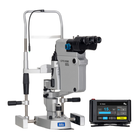
- Page 1 SLT Laser CITO Installation & Handling...
- Page 2 While every endeavour has been taken by the authors to ensure the information in this document is accurate and up to date. A.R.C. Laser shall not be liable for any personal damage or injury caused directly or indirectly, by solely using this document.
- Page 3 Service ........33 © A.R.C. Laser GmbH...
- Page 4 (at approx. 5cm dis- a trained personnel, undergone training tance) and observing the spot shape. by A.R.C. Laser or A.R.C. Laser approved 4. The device indicates when the laser is trainer. placed on “Ready“ mode. Any third per- 2.
- Page 5 7. Always switch off the laser from its „Ready“ mode when not in use; e. g. during long pauses or at the end of the procedure. © A.R.C. Laser GmbH © A.R.C. Laser GmbH...
- Page 6 LASER SAFETY LASER RADIATION & TEMPERATURE EFFECT TEMPERATURE EFFECT > 40° C Enzyme induction, membrane disaggregation, edema 45° – 65° C Tissue damage, irreversibility depends on irradiation time > 65° C Coagulation > 100° C Dehydration > 150° C Carbonisation Absorption is mainly derived by the laser radia- At low energy densities (large laser beam spot tion physical properties (wavelength).
- Page 7 LASER SAFETY BASIC LASER SAFETY INSTRUCTIONS Always switch off the laser from its „Ready“ mode when not in use; e. g. during long pauses or at the end of the procedure. READY-Screen © A.R.C. Laser GmbH...
- Page 8 UNPACKING 1. The laser packaging The CITO is shipped in three seperate boxes: The entire system includes the following parts, which can be ordered separately at any time. 1 CITO laser box 2 The slit-lamp, additional chin rest plus laser transmission and control unit.
- Page 9 UNPACKING 2. Unpacking the table ( box #3) The first layer contains the table legs and feet Layer 2 holds the table plate , that has to become joint to the legs. © A.R.C. Laser GmbH © A.R.C. Laser GmbH...
- Page 10 UNPACKING 3. Opening the table plate cover By removing the cover plates you will receive access to the table‘s plate. Inside shield 2 you have two pre installed cables The power socket that is fixed to the table needs to be removed to receive full acces to the mounting plate.
- Page 11 . At the same time make sure, that all the connectoers to power supplies are tightly + inserted Not inserting those connectors will lead to the loss of lifting ability of the table. © A.R.C. Laser GmbH © A.R.C. Laser GmbH...
- Page 12 UNPACKING 5. Mounting the feet Four screws are necessary to connect each foot to the table. Use one protector ring for each leg. Two rings are included in the package. Place the ring at the lowest end of the leg. Make sure to have the short side facing the short end of the table.
- Page 13 UNPACKING 6. Unpack the CITO laser box Open the carton - avoid cutting! Take out the cover matte, and take care for the fiber that is now visible inside the package. Take out the protective foam cover . Make sure not to bend the fiber.
- Page 14 UNPACKING Rotate the table now and put it onto its feet. Please check the position of the rubbers CIRCLE CIRCLE Open box number with the slit lamp inside.
- Page 15 4. Slit lamp +laser housing 5. Spare light bulb 6. Chin rest paper 7. Cover plugs (4pcs) 8. Screen + cable 9. Power cable, CITO 10. Tubus 11. Cable lifting table 12. Dust cover © A.R.C. Laser GmbH © A.R.C. Laser GmbH...
- Page 16 In box you will find the tubus. contains the slit lamp accessories for the CITO like Touch Screen and cables To lift the CITO out of the box please use both hands to lift the base and the slit lamp well.
- Page 17 Do not overstretch the screw. The slit lamp can be tested now me- chanically: moving it left / right or up and down to check its functionallity. © A.R.C. Laser GmbH © A.R.C. Laser GmbH...
- Page 18 SETUP THE LASER 2. Placing the cables und the housing The slit lamp cable has to go through the table placeholder as well as the laser fiber . You do not need to open the placeholder for that procedure. Take the big plate hand mount it to the table with 4 screws ( ) Please make sure that the cables will find space...
- Page 19 SETUP THE LASER 3. Placing the touch screen Place the screen onto the table and mount the monitor cable as displayed. Fix the connection with the attached screws. Do not overstretch them. © A.R.C. Laser GmbH © A.R.C. Laser GmbH...
- Page 20 SETUP THE LASER 4. Install the fiber Use a TORX screwdriver to open the small black and the large grey covers. Take away the grey cover plate to open the housing.
- Page 21 5. Insert the fiber Swing the slit lamp arm to the left side (full extent) as shown in Grab the fiber and put it through Hold the fiber and prepare yourself to insert it through © A.R.C. Laser GmbH © A.R.C. Laser GmbH...
- Page 22 SET UP THE LASER Insert the fiber Take the fiber and put it unter the arm into the housing You will need both hands for a safe installation. Now you have to screw the cap off the fiber. Store the cap at a safe place as you might need it again for service reasons.
- Page 23 Fasten the screw tightly - please work from the patient side for a better handling. ATTENTION You accidentally might break the fiber by swinging the arm back into the right side / middle. © A.R.C. Laser GmbH © A.R.C. Laser GmbH...
- Page 24 SETUP THE LASER 6. Fixate the laser fiber Use the TORX screwdriver to put on the black fiber holder. Don`t squeeze the fiber! Use the longer screw for Position 4 ATTENTION You accidentally might break the fiber by swinging the arm back into the right side / middle.
- Page 25 Close the screw as tight as possible without using too much of force. Adjust the arm handles for the patient. Our advice is an angled position. © A.R.C. Laser GmbH © A.R.C. Laser GmbH...
- Page 26 SETUP THE LASER 10. Cables for the slitlamp Make sure that the device is still without power. You will find all the necessary cables at the patient side of the system. Make sure you give them space for manouvring . The next step will be to join all the cables to supply the slit lamp and fixation light with power monitor power supply...
- Page 27 The control cable is joint to the cover plate. Please insert it to the highlighted socket at the rear of the laser box. In the end, connect the power supply for the laser box as displayed Check all the cables for tightness. © A.R.C. Laser GmbH...
- Page 28 HANDLING 1. Starting the laser For a stable stand, the table has to be put on a flat surface to avoid instability. 1. The height adjustment at the feet will help you setting up the table propperly. 2. Connect the cables to the socket, connect the mains to your wall mount.
- Page 29 Use the Energy selection button to change the values. The energy ranges from: • 0.2 mJ to 1.4 mJ, with steps of 0.1 mJ • 1.6 mJ to 2 mJ, with steps of 0.2 mJ File:Manual CITO GenII EN_0123_Rev1.0.docx © A.R.C. Laser GmbH © A.R.C. Laser GmbH...
- Page 30 HANDLING 3. Handling of slitlamp and laser Plese refer to the description below: Fixation LED Tubus: parallel or convergent Chin rest Light source Hight Display/ adjustment Interface Handle Hight level adjustment + release button Slit lamp brightness Optical lens Drum Rotator Prisma Slit color: white / Slit width...
- Page 31 HANDLING 5. Braking / Stopping Spots To losen or to fixate the slit lamp you can close (brake) or open (loosen) those three knobs by means of a small rotation. Turn clockwise to close. © A.R.C. Laser GmbH...
- Page 32 HANDLING 6. Changing the LED light Best is to open both of the light boxes. To replace the LED light only use A.R.C. Laser supplied light „bulbs“. Ask your A.R.C. representative for the proper spare parts. Unwire the LED and replace the light source as shown. Have a close look at the alignment - a flat side at the bulb will guide you.
- Page 33 SERVICE Adjustment Laser Power Cito You will need those tools: • laser power meter • PC with HyperTerminal and service cables (KB01005 Service cable serial, EL01368 USB Adapter) Step 1. Connect the PC with help of the service cable and USB Adapter with the laser.
- Page 34 SERVICE Step 3. Switch the Laser on then type Shift-S + ENTER to start service software (<S> is not displayed – can not be seen on the monitor) The screen appears Step 4. Enter menu 3 by pressing „3“ and open the shutter by pressing „a“...
- Page 35 SERVICE Step 5. Enter menu 4 Laser power by pressing „4“ The screen shows: Enter menu servo setting by pressing „l“ © A.R.C. Laser GmbH © A.R.C. Laser GmbH...
- Page 36 SERVICE • Put a laser powermeter in front of the slit lamp at the position of the laser aperture • set „c“ to 0.2mJ • set „a“ on • adjust with „d“ and „+-“ the servo position, so that the output energy is 0,2 mJ Note: When you adjust the servo motor, there is a reversal at a value of about 440.
- Page 37 . Put all the available cables and the laser fiber into it. Take care not to bend any of them. Mount the plate with its corresponding screws . Insert the plugs and switch on the laser © A.R.C. Laser GmbH © A.R.C. Laser GmbH...
- Page 38 Household Waste. please contact B2B Compliance on 01691 676124 (+44 1691 676124). 0088 EP59-70019 Issue A Home Back Next 18. Contact, packaging and disposal information A.R.C. Laser GmbH Manufacturer Scotland Sales Office USA Sales Bessemerstr. Keeler Limited Keeler Scotland Keeler USA...
- Page 39 NOTES © A.R.C. Laser GmbH...
- Page 40 SLT Laser CITO Distributor: A.R.C. Laser GmbH +49 (0) 911 217 79-0 Bessemerstraße 14 +49 (0) 911 217 79 99 D-90411 Nürnberg info@arclaser.de Germany www.arclaser.de...
Need help?
Do you have a question about the CITO and is the answer not in the manual?
Questions and answers