Table of Contents
Advertisement
Quick Links
Member of:
OWNER'S MANUAL
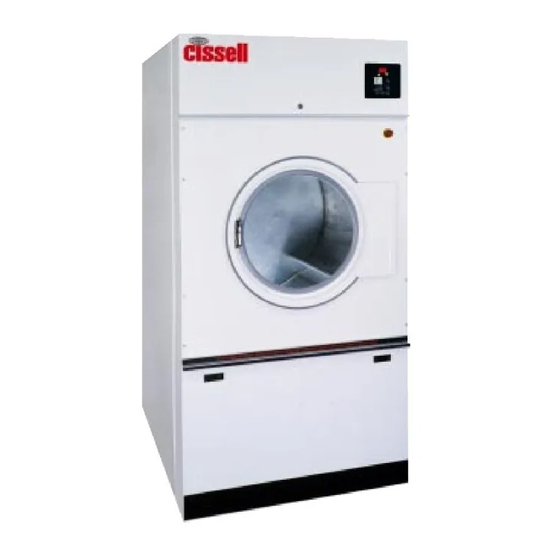
50 lb. HD LAUNDRY DRYER
Shown with manual double
timer control system
Technical specifications
Installation instructions
Operating instructions
Maintenance
Cissell Manufacturing Co.
HD50
831 S. First St. - P.O.Box 32270 - Louisville, Ky. - 40232-2270
Tel: (502) 587-1292 - Fax: (502) 585-2333 -
Sales Fax: (502) 585-3625 - Service/Parts Fax: (502) 681-1275
THIS MANUAL MUST BE GIVEN TO THE EQUIPMENT OWNER
MAN HD2050 (ECN
)
9/99
D0564
Advertisement
Table of Contents

Subscribe to Our Youtube Channel
Related Manuals for Cissell HD50


Summary of Contents for Cissell HD50
- Page 1 Technical specifications Installation instructions Operating instructions Maintenance Cissell Manufacturing Co. HD50 831 S. First St. - P.O.Box 32270 - Louisville, Ky. - 40232-2270 Tel: (502) 587-1292 - Fax: (502) 585-2333 - Sales Fax: (502) 585-3625 - Service/Parts Fax: (502) 681-1275...
-
Page 2: Safety Instructions
IMPORTANT NOTICES—PLEASE READ For optimum efficiency and safety, we recommend that you read the manual before operating the equipment. Store this manual in a file or binder and keep for future reference. WARNING: Purchaser must post the following notice in a prominent location: WARNING: For your safety, the information in this manual must be followed to minimize the risk of fire or explosion or to prevent property damage,... - Page 3 ATTENTION: L’ACHETEUR DOIT PLACER L’AVERTISSEMENT SUIVANT DANS UN ENDROIT CLAIR ET VISIBLE: AVERTISSEMENT. Assurez-vous de bien suivre les instructions donnees dans cette notice pour reduire au minimum le risque d’incendie ou d’explosion ou pour eviter tuot dommage materiel, toute blessure ou la mort. __ Ne pas entreposer ni utiliser d’essence ni d’autres vapeurs ou liquides inflammables dans le voisinage de cet appareil ou de tout autre...
- Page 4 WARNING: To avoid fire hazard, do not dry articles containing foam rubber or similar texture materials. Do not put into this dryer flammable items such as baby bed mattresses, throw rugs,undergarments (brassieres, etc.) and other items which use rubber as padding or backing. Rubber easily oxidizes causing excessive heat and possible fire.
-
Page 5: Cissell Dryer Warranty
(90) days from date of sale. The warranty period on each new replacement part furnished by Cissell in fulfillment of the warranty on new equipment or parts shall be for the unexpired portion of the original warranty period on the part replaced. -
Page 6: Table Of Contents
Contents Safety Instructions ................2-4 Cissell Dryer Warranty ................ 5 Table of Contents ................6 Symbols ....................7 Unpacking / General Installation ............8-9 Technical Data and Dimensions ............10-11 Electric Connections ................12 Gas Connections ................. 13 Gas Piping Installation ................ 14-15 Gas service Installation Instructions .......... -
Page 7: Symbols
SYMBOLS The following symbols are used in this manual and/or on the machine. S y m b o l D e s c r i p t i o n S y m b o l Rotation in two directions Rotation dans les deux sens NOTE! Drehbewigung in zwei... -
Page 8: Unpacking / General Installation
Unpacking/General Installation (All Dryers) Upon arrival of the equipment, any damage in shipment UNPACKING should be reported to the carrier immediately. Upon locating permanent location of a unit, care should be taken in movement and placement of equipment. See outline clearance diagrams for correct dimensions. Remove all packing material such as: tape, manuals, skid, Leveling: Use spirit level on top of dryer. - Page 9 Unpacking/General Installation (All Dryers) The dryer is so designed that when an operator opens the GENERAL dryer door, the basket and exhaust fan stop. You can INFORMATION expect fast drying from the laundry dryer. Hot, dry air is properly and effectively moved through the basket and exhausted through a lint trap to the atmosphere.
-
Page 10: Technical Data And Dimensions
50 lb. Dryer Dimensions - Standard Gas, Steam and Electric Heated " " " " " Page 10... - Page 11 HD50 Dryer Dimensions - Gas ( I l l u s t r a t i o n ) 34.87“ (880 mm) 49.5“(1260 mm) 12.2“(310 mm) Steam Ret. 9.25“(235 mm) Steam Conn. ELECTR IC BOX CON. Electric 9.1“(230 mm) Inlet Gas Conn.
-
Page 12: Electric Connections
Electric connection Dryers must be electrically grounded by a separate #14 or larger green wire from the grounding terminal within the Service Connection Box, to a cold water pipe. In all cases, the grounding method must comply with local electrical code requirements; or in the absence of local codes, with the National Electrical Code, ANSI/NFPA 70 or the Canadian Electrical Code, CA C22.1. -
Page 13: Gas Connections
Gas connection The gas supply pipe should be connected to the gas tap (I), which is on the right next to the wiring box on the back. It is very important to have the connections done by a qualified technician, in order to make sure that the installation is effected in accordance with the prevailing standards and instructions. -
Page 14: Gas Piping Installation
Gas Piping Installation 1. The installation must conform with local codes, or in PIPING the absence of local codes with the National Fuel INSTALLATION Gas Code as, ANSI Z223.1 or the CAN/CGA- B149, Installation Codes. 2. Check identification nameplate for type of gas for dryer. - Page 15 Gas Piping Installation (Illustrations) The dryer and it’s individual shutoff valve must be disconnected from the gas supply piping system during any pressure testing of that system at test pressures in excess of 1/2 psi (.04 bar). The dryer must be isolated from the gas supply piping system by closing it's individual manual shutoff valve during any pressure testing of the gas supply piping system at test pressures equal to or less than 1/2 psi (.04 bar).
-
Page 16: Gas Service Installation Instructions
Gas Service Installation Instructions The size of the gas service pipe is dependant upon many SERVICE variables, such as tees, lengths, etc. Specific pipe size INSTALLATION should be obtained from the gas supplier. Refer to the “Gas INSTRUCTIONS Pipe Size” chart in this manual for general gas pipe size information. -
Page 17: Gas Pipe Size Chart
Gas Pipe Size Chart TOTAL BTU/HR GAS PIPE SIZE FOR 1000 BTU (250 KCAL) NATURAL GAS (for LP Gas correct AT 7” (17.5 MM) W.C. PRESSURE TOTAL total BTU/HR below by KCAL multiplying by .6) In figuring total length of pipe, make allowance for tees and elbows. H O U R (25 ft.) (50 ft.) -
Page 18: Dryer Installation With Multiple Exhaust
Dryer Installation With Multiple Exhaust For Exhaust Duct less than 14 feet (5 m) and 2 elbows equivalent and less than 0.3 inches (8 mm) static pressure. DRYER EXHAUSTS Area of section “A-A” must be equal to the sum of dryer exhaust pipes entering multiple exhaust pipe. - Page 19 Dryer Installation with Multiple Exhaust For Exhaust Duct more than 14 feet (5 m) and 2 elbows equivalent DRYER INSTALLATION and more than 0.3 inches (8 mm) static pressure. WITH MULTIPLE (See illustration on page 21.) EXHAUST 1. Make-up air from outside building may enter enclosure from top or side walls.
-
Page 20: Dryer Make-Up Air Requirements
3000 5100 3716 HD20 HD30 13.6 1063 HD50 22.7 1190 HD75 1275 Notes: 1) The Model C 30 ST has 2 pockets per dryer, each pocket has the above listed characteristics; each pocket is exhausted separately with a 6" (153mm) duct. -
Page 21: Dryer Installation With Seperate Exhaust
Dryer Installation With Separate Exhaust (Preferred) For ductwork less than 14 feet (5 m) and 2 elbows equivalent DRYER INSTALLATION and less than 0.3 inches (8 mm) static pressure: WITH SEPARATE EXHAUST (PREFERRED) NEVER exhaust the dryer into a chimney. NEVER install wire mesh screen over the exhaust or make-up air area. -
Page 22: Exhaust And Venting
Exhaust and Venting DRYER AIR FLOW Nothing is more important than air flow for the proper operation of a INSTALLATION clothes dryer. A dryer is a pump which draws make-up air from the out- of-doors, through the heater, through the clothes and then forces the air through the exhaust duct back to the out-of-doors. -
Page 23: Rules For Safe Operation Of Dryer
Rules for Safe Operation of Dryer 1. Be sure your dryer is installed properly in accordance with the recommended instructions. 2. CAUTION Be safe—shut main electrical power supply and gas supply off externally before attempting service. 3. CAUTION Never use drycleaning solvents: gasoline, kerosene, or other flammable liquids in the dryer. -
Page 24: Direct-Spark Ignition Operation
Direct-Spark Ignition Operation NOTE: dryers manufactured are equipped with the DIRECT SPARK (direct spark ignition) modules. These are designed to increase dryer IGNITION efficiency and to reduce dryer operating costs. The main burner is OPERATION directly ignited from a spark electrode. A burning flame provides an electrical path for a small amount of sensing current to allow gas valve operation. - Page 25 DIRECT SPARK IGNITION OPERATION FLOW CHART The DSI module is powered by a 24 volts AC suppled by a step-down trans- former in series with eight safety interlocks: A. Timer switching device (1) B. Main door and lint door switches (2) C.
-
Page 26: General Maintenance
General Maintenance 1. Clean lint trap daily. Remove lint before or after GENERAL MAINTENANCE each day of operation. A clean lint trap will increase the efficiency of the dryer and the moisture-laden air will be exhausted outside more quickly. 2. Keep basket and sweep sheets clean. Clean as often as needed. - Page 27 General Maintenance 7. Periodically clean and examine exhaust system. GENERAL MAINTENANCE ( c o n t i n u e d ) 8. Keep dryer area clean and free of gasoline, combustible materials and other flammable liquids or vapors. 9. Do not obstruct the flow of combustion (make-up) air and ventilating air.
-
Page 28: Operating Instruction For Double Timer
OPERATING INSTRUCTION - DOUBLE TIMER OPERATING INSTRUCTIONS - DOUBLE TIMER MODELS 1. After loading the dryer with water washed clothes, close the loading door. 2. Turn the 60 minute drying (heat) timer to the desired time. 3. Turn the 60 minute cooling (air) to the desired time. 4. -
Page 29: Parts
FRONT VIEW Ref. Part No. Description Ref. Part No. Description CB36 Screw -hex 1/4-20 X 1/2" CSA50037WH Jacket fas/electric (white) TU2846 Lockwasher 1/4" medium CSA-50050WH Jacket steam (white) TU2847 Washer 1/4" TU7733 Screw self drilling 8-18 X 1/2" CA-10567-0 Lint frame CA-12073-0 Top panel CA-13033... -
Page 30: Control Door Assembly
CONTROL DOOR ASSEMBLY CSA-01423WH Complete control door assy. Note: Door rod assy. is not part of above complete assy. Ref. Part No. Description CSA-01424WH Control door assy. CA-00857-0 Trim - Control door CA-11941-0 Cam lock-Control door CA-00121-0 Lock - Control door CA-00119-0 Key - Control door CA-13098-0... -
Page 31: Front Panel Assembly
FRONT PANEL ASSEMBLY Ref. Part No. Description SB-00915-0 Screw self drilling #10-16 X 5/8 CSA-01566WH Front panel, welded assy.-Coin CSA-01565WH Front panel, welded assy-OPL TU3213 Pop Rivet PVD doorlocker TU2876 Latch strap CA-00676 Insulation SB-00924-0 Screw 4-40*3/8 taptite SB-00938-0 Washer 4 external tooth CA-00699-0 Bezel - Coin box ESA-00862-0... -
Page 32: Thermostat Assembly
THERMOSTAT ASSEMBLY NOTE: Items 1 thru 6 mounted in front wire box. Ref. Part No. Description Items 7 thru 12 are mounted under the basket EA-00607-0 Thermostat knob CA-13213-0 Thermostat bracket EA-00606-0 Thermostat CA-13215-0 Thermostat bracket adapter TU3624 Screw 6 - 32 X 1/4" TU7733 Screw - self drilling 8 - 18 X 1/2"... -
Page 33: Wire Box Assembly
WIRE BOX ASSEMBLY Ref. Part No. Description CSA-01608WH Wire box door assy complete TUT316 Light LED 24V EA-11614-0 Timer-manual 24V - 60 min. complete EA-00619-0 Switch - start CA-13170-0 Overlay- dual timer non-rev CSA-01608WH Wire box door assy. SB-00865-0 Screw-self drilling #6-20 X 12" EA-00210-0 Terminal block ESA-00967-0... -
Page 34: Door Assembly
DOOR ASSEMBLY Ref. Part No. Description MSD-00864WH Complete door assy (consists of items 1 thru 9 only) MD-00362-0 Door Glass - clear MD-00354-0 Gasket - door glass - straight TU3163 Catch Pin TU4840 Crown nut MD-00337-0 Magnet - read switch MD-00338-0 Gasket - door rim TU2874... -
Page 35: Lint Door Assembly
LINT DOOR ASSEMBLY For OPL models only. Ref. Part No. Description CSA-01430WH Complete Asm - WMC50 OPL CSA-01428WH Complete Asm - WMC50 Coin CSA-01099WH Lint door w/latch holes(white) OPL CSA-01429WH Lint door w/lock holes(white) Coin CSA-00838-0 Kickplate SB-00949-0 Fastener plastic kickplate CA-12029-0 Insulation lower frontpanel WMC50 SB-00915-0... -
Page 36: Basket & Spider Assembly
BASKET & SPIDER ASSEMBLY Ref. Part No. Description CSA-01541-0 Basket & Spyder Asm.WMC50 - S.S. CSA-01632-0 Basket & Spyder Asm.WMC50 - Galv. CSA-01540-0 Stainless steel basket assy. CSA-01631-0 Galvanized basket assy. CSA-00822-0 Spider assy. TU5439 Screw-cap 5/16-18 X 3/4" TU2814 Lock washer 5/16"... -
Page 37: Rear View
REAR VIEW Ref. Part No. Description CA-12073-0 Top panel TU7733 Screw self drilling 8-18*1/2" CA-11936-0 Cover plate CA-12016-0 Backpanel TU7733 Screw self drilling 8-18*1/2" Page 37... -
Page 38: Air Switch Assembly
AIR SWITCH ASSEMBLY Ref. Part No. Description CSA-01334-0 Sail switch assy. complete CA-11854-0 Bracket sailswitch SB-00955-0 Screw phillips #4 X 3/4" TU7733 Screw self drilling 8-18*1/2" CSA-01669-0 Sailswitch plate and rod assy. SB-00954-0 Clip-twin-Tinnerman EA-00618-0 Microswitch Page 38... - Page 39 BASKET BEARINGS, SUPPORT, AND SHEAVE Ref. Part No. Description Ref. Part No. Description DA-11912-0 Pulley - basket Part of pulley DA-11914-0 IB140 Washer 3/8" C249 Hex nut 5/16-18" IB139 Screw 3/8-16*1-1/4" SB-00876-0 Stud - 5/16 - 18" IB139 Screw 3/8-16*1-1/4" DSA-00728-0 Bearing box assy.
-
Page 40: Motor & Fan Assembly
MOTOR & FAN ASSEMBLY- NON-REVERSING Ref. Part No. Description DA-00494-0 Fan motor 1/2 HP 115/208/230/60/50/1 DA-00447-0 Fan motor 1/2 HP 220/380/60/50/3 TU2814 Lock washer 5/16" TU5439 Screw-cap 5/16-18 X 3/4" DSA-00782-0 Motor mount w/a - non-rev. SB-00842-0 Nut, grip, Tinnerman SB-00836-0 Screw, phillips, pancake head DSA-00773-0... -
Page 41: Idler Assembly
IDLER ASSEMBLY Ref. Part No. Description Ref. Part No. Description C249 Hex Nut 5/16-18" DA--11904-0 Idler pulley 11" TU2814 Lock Washer 5/16" DA-00917-0 Basket belt - non-reversing - AX70 VSB130 Washer 5/16" DA-00497-0 Basket belt -reversing - AX71 SB-00935-0 Screw 5/16"-18 X 3" FB124 Screw 5/16-18*1"... -
Page 42: Rear Control Panel Assembly
REAR CONTROL PANEL ASSEMBLY Ref. Part No. Description ESA-00966-0 Wire box assy, rear, gas - 115V - 2 timer ESA-00974-0 Wire box assy, rear, gas - 208/240V - 2 timer CA-11935-0 Rear wiring box Ref. Part No. Description SB-00868-0 Bushing, insulating 7/8" SB-00867-0 Bushing, insulating 1/2"... -
Page 43: Gas Heating Unit Assembly
GAS HEATING UNIT Ref. Part No. Description Ref. Part No. Description GSA-0778-0 Comp. assy. - Nat. gas OP314 Union (gas pipe) GSA-00255-0 Housing gas burner GSA-00508-0 Manifold assy. TU11613-0 Lock washer 10 external tooth TU7733 Screw self drilling 8-18X1/2" SB-00831-0 Screw 10-32*3/8"...
Need help?
Do you have a question about the HD50 and is the answer not in the manual?
Questions and answers