
Related Manuals for multicomp pro MP751061


Summary of Contents for multicomp pro MP751061
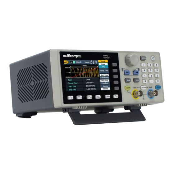
- Page 1 Dual-Channel Arbitrary Waveform Generator User Manual Part Number: MP751061 / MP751062 Newark.com/multicomp-pro Farnell.com/multicomp-pro sg.element14.com/b/multicomp-pro Page <1> 15/03/24 V1.0...
-
Page 2: Table Of Contents
Table of Content 1. General Safety Requirement ..............4 2. - Page 3 PSK (Phase Shift Keying) . . . . . . . . . . . . . . . . . . . . . . . . . . . . . . . . . . . . . . . . . . . . . . . . . . . . . . . . . . . . . . . . . . . . . 29 FSK (Frequency Shift Keying) .
-
Page 4: General Safety Requirement
1. General Safety Requirement Before any operations, please read the following safety precautions to avoid any possible bodily injury and prevent this product or any other products connected from damage. In order to avoid any contingent danger, this product is only used within the range specified. -
Page 5: General Inspection
3. General Inspection After you get a new generator, it is recommended that you should make a check on the instrument according to the following steps: 1. Check whether there is any damage caused by transportation. If it is found that the packaging carton or the foamed plastic protection cushion has suffered serious damage, do not throw it away first till the complete device and its accessories succeed in the electrical and mechanical property tests. -
Page 6: Rear Panel Overview
Operation key (Utility) set the utility function Power button Turn on/off the waveform generator. Number keypad Input the parameter On/Off button Turns the output of the CH2 channel on or off. When the output is turned on, the backlight of the button lights up. Out 2 Output CH2 signal CH1/CH2... -
Page 7: User Interface
User Interface Display channel name Display channel switch status Display load Current mode When the instrument detects the USB flash drive, it lights up the indicator Lights up the indicator when connected to the USB Host via the USB DEVICE interface. Buzzer Menu title Current waveform or mode setting menu. -
Page 8: Turn On/Off Channel Output
← → To edit parameter: Turn the knob to change the value of cursor position. Press 8 direction key to move the cursor. (The number keys can not be used to input.) Turn on/off channel output Press CH1 On/Off or CH2 On/Off on the front panel to turn on/off the corresponding channel output. The backlight of the button will light up when it is set to output. -
Page 9: Set The Frequency/Period
Set the frequency/period • Press CH1/CH2, Select Display CH1 channel. • Press the On/Off button on the CH1, enable channel CH1. • Press the Frequency/Period softkey, the selected menu item is highlighted in white, and a cursor will display on the corresponding parameter item in Parameter 1 . -
Page 10: Output Square Wave
Set the Phase Press the Phase softkey, the Phase menu item is highlighted. In Parameter 4 of Figure 5 2, cursor appears in the parameter value of Phase. Turn the knob to change the value directly, or use the numeric keypad to input the desired value and choose the unit. -
Page 11: Set The Symmetry
Set the symmetry Press the Symmetry softkey, the Symmetry menu item is highlighted. In Parameter 5 of Figure 5 5, cursor appears in the parameter value of symmetry. Turn the knob to change the value directly, or use the numeric keypad to input the desired value and choose the unit. -
Page 12: Set The Pulse Width/Duty Cycle
Set the pulse width/duty cycle Press the Width/DutyCyc softkey, the chosen menu item is highlighted. Press the Width/DutyCyc softkey to switch between Pulse Width and Duty Cycle. In Parameter 5 of Figure 5 7, cursor appears in the parameter value. Turn the knob to change the value directly, or use the numeric keypad to input the desired value and choose the unit. -
Page 13: Set The Rising Time
Set the rising time Press the Rise softkey, the chosen menu item is highlighted. Press the Rise softkey to switch between Rising Time and Falling Time . In Parameter 6 of Figure 5 7, cursor appears in the parameter value. Turn the knob to change the value directly, or use the numeric keypad to input the desired value and choose the unit. -
Page 14: Output Noise Wave
Output Noise Wave The noise wave which the generator output is white noise. Press , the screen displays the user interface of the noise wave. The Noise waveform parameters can be set by operating the Noise setting menu on the right. The noise wave has no frequency and periodic parameters and is Gaussian noise with a bandwidth of 20MHz4. -
Page 15: Select Build-In Wave (Including Dc)
Select build-in wave (including DC) There are 160 types of waveforms built in the generator, the number of waveform points is 8192 points, and the highest upper limit frequency is 10MHz. To select a built-in waveform, the steps are as follows: Arb wave button, then press the NextPage softkey to enter the nextpage menu. - Page 16 StairUD Stair upward/downward StairUp Stair upward Trapezia Trapezia Medical treatment Heart Heart Cardiac Cardiac LFPulse Low frequency pulse electrotherapy waveform Tens1 Neuroelectric stimulation therapy waveform 1 Tens2 Neuroelectric stimulation therapy waveform 2 Tens3 Neuroelectric stimulation therapy waveform 3 Electrooculogram Electroencephalogram Pulseilogram Ordinary pulse curve ResSpeed...
- Page 17 Laguerre Four Laguerre polynomials Laplace Laplace distribution Legend Five Legendre polynomials Gauss Gaussian distribution, also known as the normal distribution HaverSine Semi-positive function Base 10 logarithmic function LogNormal Lognormal distribution Lorentz Lorentz function Maxwell Maxwell distribution Rayleigh Rayleigh distribution Versiera Tongue line Weibull Weber distribution...
- Page 18 ACosH Inverse hyperbolic cosine function ACot Anti-cotangent function ACotCon Inverse cotangent function ACotPro Raised inverse cotangent function ACotH Inverse hyperbolic cotangent function ACotHCon Inverse hyperbolic cotangent function ACotHPro Raised inverse hyperbolic cotangent function Acsc Anti-cosecting function ACscCon Concave inverse cosecting function ACscPro Raised anti-cosecting function AcscH...
-
Page 19: Store
Engineering Window Butterworth Butterworth filter Combin Combined function CPulse C-Pulse signal CWPulse CW pulse signal RoundHalf Half-round wave BandLimited Band limited signal BlaseiWave Blasting vibration “time-vibration speed” curve Chebyshev1 Type I Chebyshev filter Chebyshev2 Type II Chebyshev filter DampedOsc Damped oscillation “time-displacement” curve DualTone Dual audio signal Gamma... -
Page 20: Generate Sweep (Sweep)
(3) Enter the “Waveform Editor” interface. (4) Select the required waveform on the instrument. (5) Under Waveform Editor software interface, click “Read Waveform Icon “ button, and the waveform will be read and displayed on the screen . Write and Recall waveform We can use the Line Draw, Hand Draw and Point Edit mode in the Waveform Editor to edit the required waveform, and save and display it on the instrument by writing. - Page 21 How to set the parameters of Sweep (1) When the output signal is Sine, Square, Ramp or Arbitrary wave (except DC), press the front panel Mode function key, then press the Sweep to enter the sweep mode . (2) Press , or to select the sweep waveform.
-
Page 22: Generate Burst (Burst)
Generate Burst (Burst) Press the Mode key on the front panel, then press the Burst to generate versatile waveforms in burst. Burst can last for certain times of waveform cycle (N-Cycle Burst), or to be controlled by external gated signals (Gated Burst). Burst can apply to Sine, Square, Ramp, Pulse and Arbitrary waveforms (except DC). -
Page 23: Set Gated Burst
Note: • If needed, Burst Period will increase to cater to the specific number of cycles. • For an infinite-cycle Burst, External or Manual Trigger is needed to activate burst. (4) Burst trigger source could be internal, external or manual. The generator will generate a burst output when a trigger signal is received and then wait for the next trigger. -
Page 24: Output The Modulated Waves
Output the Modulated Waves Supported modulation types include:AM(Amplitude Modulation), FM (Frequency Modulation), PM (Phase Modulation), PWM (Pulse Width Modulation), ASK (Amplitude Shift Keying), PSK (Phase Shift Keying), FSK). (Frequency Shift Keying), 3FSK (Ternary Frequency Shift Keying), 4FSK (Quadrature Frequency Shift Keying), BPSK (Biphase Phase Shift Keying), QPSK (Quadrature Phase Shift Keying), OSK (Oscillating Keying), SUM (Sum Modulation), DSBAM (Double-Sideband Amplitude Modulation). -
Page 25: Dsb-Am (Double-Sideband Am)
(7) Set modulation depth: Press the Depth softkey to set the modulation depth. The range is 0% - 100%. Glossary AM frequency The frequency of the modulating waveform. Modulation Depth The amplitude range of modulating waveform. In 0% modulation, the output amplitude is half of the specified value. In 100% modulation, the output amplitude is equal to the specified value. -
Page 26: Pm (Phase Modulation)
(6) Set modulating wave frequency: Press the AM Frequency softkey to set the modulating wave frequency. The range is 2 mHz – 100 kHz (for internal source only). (7) Set modulation depth: Press the Depth softkey to set the modulation depth. The range is 0% - 100%. PM (Phase Modulation) The modulated waveform consists of the carrier wave and the modulating wave. - Page 27 (7) Set frequency deviation: Frequency deviation is the deviation of the modulating wave frequency relative to the carrier wave frequency. Press the Deviation softkey to set the FM frequency deviation. Frequency deviation range: 1 uHz ≤ deviation < min (min is carrier frequency or carrier maximum frequency minus carrier frequency, the smaller of the two).
-
Page 28: Pwm (Pulse Width Modulation)
PWM (Pulse Width Modulation) The modulated waveform consists of the carrier wave and the modulating wave. For PWM, the pulse width of the carrier Pulse wave varies with the instantaneous voltage of the modulating wave. The PWM user interface is shown below. How to set the parameters of PWM (1) Set carrier wave shape: PWM can only be used to modulate pulse, so the carrier wave must be Pulse . -
Page 29: Psk (Phase Shift Keying)
How to set the parameters of ASK (1) Press the Mode function key, press the NextPage softkey,then press the ASK softkey to enter ASK user interface. (2) Select carrier wave shape: The carrier wave can be Sine, Square, Ramp, or Arbitrary wave (except DC). Press , or to select a desired carrier wave shape . -
Page 30: Fsk (Frequency Shift Keying)
How to set the parameters of PSK (1) Press the Mode function key, press the NextPage softkey twice more, then press the PSK softkey to enter PSK user interface. (2) Select carrier wave shape: The carrier wave can be Sine, Square, Ramp, or Arbitrary wave (except DC). Press , or to select a desired carrier wave shape . -
Page 31: 3Fsk (3 Frequency Shift Keying)
(4) Select wave source: Press the Source softkey to select Internal or External as the modulating wave source. If you select Internal, the modulating wave is set as a Square with 50% duty cycle. Press the FSK Rate softkey to set the FSK rate. -
Page 32: 4Fsk (4 Frequency Shift Keying)
4FSK (4 Frequency Shift Keying) 4 Frequency Shift Keying modulation is a modulation technique that shifts the output signal frequency among four preset frequencies: the carrier frequency and three hop frequencies. The shift frequency (4FSK rate) is determined by the internal signal level of the instrument. -
Page 33: Qpsk (Quadrature Phase Shift Keying)
How to set the parameters of BPSK (1) Press the Mode function key, press the NextPage softkey three more times,then press the BPSK softkey to enter BPSK user interface. (2) Select carrier wave shape: The carrier wave can be Sine, Square, Ramp, or Arbitrary wave (except DC). Press , or to select a desired carrier wave shape . -
Page 34: Osk (Oscillation Shift Keying)
How to set the parameters of QPSK (1) Press the Mode function key, press the NextPage softkey three more times, then press the QPSK softkey to enter QPSK user interface. (2) Select carrier wave shape: The carrier wave can be Sine, Square, Ramp, or Arbitrary wave (except DC). Press , or to select a desired carrier wave shape . -
Page 35: Sum (Sum Modulation)
(5) Set OSK rate: Press the OSK Rate softkey to set the OSK rate. The intermittence time and oscillate time of the output signal is determined by OSK rate (for internal source). The range is 2 mHz – 100 kHz. (6) Set oscillate time: Oscillate time is the oscillation period of internal crystal oscillator. -
Page 36: Utility Function Setting
Utility Function Setting Press the front panel Utility function key to enter the utility menu. You can set the parameters of the generator such as: display settings, CH1/2 settings, and system settings. Press Utility again to exit the utility menu. Display Settings Brightness Control (1) Press the front panel Utility function key, press the Display softkey. -
Page 37: Sync
Sync The generator can output the sync signals of basic waveforms (except noise), arbitrary waveforms (except DC), sweep signal, burst signal, and modulated signal from a single channel or two channels at the same time. The steps to enable or disable sync signal at the Sync/Ext Mod/Trig/FSK connector: (1) Press the Utility function key, press the CH1/2 Set softkey. -
Page 38: Restore To The Factory Setting
• PC: This is the internal communication protocol. Select this option when connecting to the Waveform Editor software via the USB Device interface . • USB TMC: Select this option when you need to use the USB TMC communication protocol standard. Restore to the factory setting (1) Press the front panel Utility function key, select System softkey, then press the Nextpage softkey. - Page 39 Frequency Deviation 100 Hz Modulation Source Internal Modulating Waveform Sine PM Frequency 100 Hz Phase Deviation 0° Modulation Source Internal Modulating Waveform Sine PWM Frequency 100.000 0 Hz Duty Cycle Deviation Modulation Source Internal ASK Rate 100.000 0 Hz Modulating Amplitude 1.000 Vpp Modulation Source Internal...
-
Page 40: Firmware Update
OSK Rate 1.000 000 kHz Oscillate Time 100.000 us Sweep Factory Setting Sweep Time 1 .000 000 s Sweep Type Linear Start Frequency 100.000 0 Hz Stop Frequency 1.000 000 kHz Center Frequency 550.000 0 Hz Frequency Span 900.000 0 Hz Trigger Source Internal Burst... -
Page 41: Counter
3. Visit the company’s website on the PC and select the required instrument firmware upgrade package for the corresponding model. Download the “ AG. upp “ file in the firmware upgrade package to the PC, and copy the firmware to the external disk that is displayed . -
Page 42: Specification
(20°C to 30°C) to meet these specifications; • The signal generator is in the calibration internal and has performed a self-calibration. In addition to the specifications marked with the word “Typical”, the specifications used are guaranteed. Waveforms Waveforms MP751061 30 MHz Bandwidth MP751062 60 MHz... -
Page 43: Amplitude Characteristics
Amplitude Characteristics (not specifically labeled, the load defaults to 50Ω) 2mVpp ~ 20Vpp (≤ 10MHz) High Z 2mVpp ~ 10Vpp (≤ 30MHz) High Z MP751061 1mVpp ~ 10Vpp (≤ 10MHz) 50 Ω 1mVpp ~ 5Vpp (≤ 30MHz) 50 Ω Output amplitude 2mVpp ~ 20Vpp (≤... -
Page 44: Modulation Characteristics
Ramp < 1% of peak output Linearity (typical 1 kHz, 1 Vpp, symmetry 50%) Symmetry 0% to 100% Pulse MP751061 67 ns to 1 Ms Period MP751062 50 ns to 1 Ms Pulse Width ≥ 24ns Rise and fall time ≥... - Page 45 DSBAM Carrier Sine wave, square wave, ramp wave,arbitrary wave (except DC) Modulated signal source Internal or external Internal modulation waveform Sine wave, square wave, ramp wave Internal amplitude modulation frequency 2 mHz to 100 kHz Depth 0% to 100% Carrier Sine wave, square wave, ramp wave, arbitrary wave (except DC) Modulated signal source Internal or external...
- Page 46 Carrier Sine wave, square wave, ramp wave, arbitrary wave(except DC) Modulated signal source Internal or external Internal modulation waveform 50% square wave FSK rate 2 mHz to 1MHz FSK hopfreq 2 mHz ≤ offset < maximum frequency of corresponding carrier 3FSK Carrier Sine wave, square wave, ramp wave, arbitrary wave(except DC)
-
Page 47: Sweep Characteristics
N-cycle trigger source Internal, external, manual Carrier frequency 1 μHz ≤ Offset ≤ Maximum frequency of corresponding carrier /2 MP751061 67 ns - 1 Ms (Min = Cycles * Period) N-cycle trigger cycle MP751062 34 ns - 1 Ms (Min = Cycles * Period) -
Page 48: General Specifications
Sync Output Level TTL-compatible Maximum frequency 1MHz General Specifications Display Display type 3.6-inch colour LCD display Display resolution 480 Horizontal × 272 Vertical pixels Display colour 65536 colours, 16 bits, TFT Power Voltage 100V AC to 240V AC, 50/60 Hz, CATII Power consumption Less than 20W Fuse... - Page 49 Group was aware of the possibility of such loss or damage arising) is excluded. This will not operate to limit or restrict the Group’s liability for death or personal injury resulting from its negligence. Multicomp Pro is the registered trademark of Premier Farnell Limited 2019.
Need help?
Do you have a question about the MP751061 and is the answer not in the manual?
Questions and answers