
Related Manuals for multicomp pro MP751059


Summary of Contents for multicomp pro MP751059
- Page 1 Dual-Channel Arbitrary Waveform Generator User Manual Part Number: MP751059 / MP751060 Newark.com/multicomp-pro Farnell.com/multicomp-pro sg.element14.com/b/multicomp-pro Page <1> 15/03/24 V1.0...
-
Page 2: Table Of Contents
Table of Content 1. General Safety Requirement ..............4 2. - Page 3 Separator . . . . . . . . . . . . . . . . . . . . . . . . . . . . . . . . . . . . . . . . . . . . . . . . . . . . . . . . . . . . . . . . . . . . . . . . . . . . . . . . . . 27 CH1/2 Settings .
-
Page 4: General Safety Requirement
1. General Safety Requirement 2. Safety Terms and Symbols Safety Terms Terms in this Manual. The following terms may appear in this manual: Warning: Warning indicates the conditions or practices that could result in injury or loss of life. Caution: Caution indicates the conditions or practices that could result in damage to this product or other property. Terms on the Product. -
Page 5: Quick Start
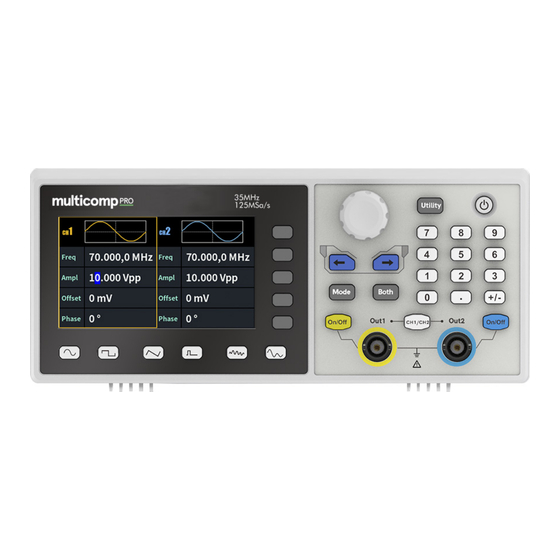
4. Quick Start Front Panel Overview Display the user interface Menu selection keys Includes 5 keys to activate the corresponding menu Operation keys Mode: output the modulated waveform Both: Display the editable parameters of both channels. Knob Change the currently selected value, also used to select the arbitrary waveform types and arb data file name. -
Page 6: Rear Panel Overview
Rear Panel Overview Air vents Power input connector DC power input connector Foot Stool Tilt the signal generator for easy operation . Used to connect a USB type B controller. Can be connected with PC, the signal USB Device interface generator can be controlled by the host computer software. -
Page 7: Panel Operation
Display channel name Display channel switch status Display load Current waveform mode Lights up the indicator when connected to the USB Host via the USB DEVICE interface Buzzer Menu title Current waveform or mode setting menu Start phase Offset / low level, depending on the right highlighted menu item Amplitude / high level, depending on the right highlighted menu item Frequency/Period, depending on the highlighted menu item on the right Display current waveform... -
Page 8: Waveform Setting
Waveform Setting Sine, square, ramp, pulse, noise or arbitrary waves can be set and output. Press the waveform selection button on the front panel: sine , square , ramp , pulse , noise , arbitrary wave , and enter the corresponding wave- form setting interface. -
Page 9: Set The Amplitude
Set the amplitude Press the Amplitude/High Level softkey to confirm whether the Amplitude menu item is highlighted; if not, press the Amplitude/High Level sofkey to switch to Amplitude . In Parameter 2 of Figure 5 2, a blinking cursor appears in the parameter value of amplitude. -
Page 10: Output Ramp Wave
Output Ramp Wave Press , the screen displays the user interface of the ramp wave. The Ramp waveform parameters can be set by operating the Ramp setting menu on the right. The ramp menu includes: Frequency/Period, Amplitude/High Level, Offset/Low Level, Phase, and Symmetry . To set the Frequency/Period, Amplitude/High Level, Offset/Low Level, Phase, please refer to Output Sine Wave. -
Page 11: Output Pulse Wave
Glossary Symmetry: Sets the percentage of the period during which the ramp waveform is rising. Output Pulse Wave Press , the screen displays the user interface of the pulse wave. The Pulse waveform parameters can be set by operating the Pulse setting menu on the right. The pulse wave menu includes: Frequency/Period, Amplitude/High Level, Offset/Low Level, Phase, Pulse Width/Duty Cycle, and RiseTime/FallTime . -
Page 12: Set The Pulse Width/Duty Cycle
Set the pulse width/duty cycle Press the Width/DutyCyc softkey, the chosen menu item is highlighted. Press the Width/DutyCyc softkey to switch between Pulse Width and Duty Cycle. In Parameter 5 of Figure 5 7, a blinking cursor appears in the parameter value. Turn the knob to change the value directly, or use the numeric keypad to input the desired value and choose the unit. -
Page 13: Set The Rising/Falling Time
Pulse/Duty Cycle The pulse width is defined as the time interval from the 50% threshold of the amplitude of the rising edge of the pulse to the 50% threshold of the amplitude of the next falling edge, as shown in the following figure. •... -
Page 14: Output Arbitrary Wave
Output Arbitrary Wave Press , the screen displays the user interface of the arbitrary wave. The Arbitrary waveform parameters can be set by operating the Arbitrary setting menu on the right. The arbitrary wave menu includes: Frequency/Period, Amplitude/High Level, Offset/Low Level, Phase, Built-in Waveform and Store . - Page 15 Built-in wave list Name Description Common Direct current AbsSine Absolute sine AbsSineHalf Absolute half-sine AmpALT Gain oscillation curve AttALT Attenuation oscillation curve GaussPulse Gauss pulse NegRamp Negative ramp NPulse Negative pluse PPulse Positive pluse SineTra Sine-Tra wave SineVer Sine-Ver wave StairDn Stair downward StairUD...
- Page 16 Sintering temperature release map Surge Surge signal Maths Airy Airy function Besselj Type I Bessel function Bessely Type II Bessel function Cauchy Cauchy distribution Cubic function Error function Erfc Remnant error function ErfcInv Anti-complement error function ErfInv Inverse error function Dirichlet Dirichlet function ExpFall...
- Page 17 Cosecant CscPro Raised cosecant CscH Hyperbolic cosecant CscHCon Depressed hyperbolic cosecant CscHPro Raised hyperbolic cosecant RecipCon Reciprocal of the depression RecipPro Raised countdown SecCon Depression secant SecPro Raised secant SecH Hyperbolic secant Sinc Sinc function SinH Hyperbolic sine Sqrt Square root function Tangent function TanH Hyperbolic tangent...
- Page 18 Blackman Blackman window BlackmanH BlackmanH window BohmanWin BohmanWin window Boxcar Rectangular window ChebWin Chebyshev window FlattopWin Flat top window Hamming Hamming window Hanning Hanning window Kaiser Kaiser window NuttallWin The smallest four Blackman-Harris windows ParzenWin Parzen window TaylorWin Taylaor window Triang Triangle window, also call Fejer window TukeyWin...
- Page 19 Segement Modulation Sinusoidal segmented AM wave Sinusoidal segmented FM wave Sinusoidal segmented PM wave Pulse width segmented PWM wave Fan test 64n/1024 Order adjustment (n is an integer, the range is 0 - 16) File Sore Syetem Supports communication with a computer via a USB port. Using the Waveform Editor software installed on the computer, the signal generator can be operated on the computer to control the output and write the file to the signal generator.
-
Page 20: Generate Sweep (Sweep)
Write and Recall waveform We can use the Line Draw, Hand Draw and Point Edit mode in the Waveform Editor to edit the required waveform, and save and display it on the instrument by writing. (1) Under Waveform Editor software interface, Click “Write waveform lcon” button. -
Page 21: Generate Burst (Burst)
How to set the parameters of Sweep (1) When the output signal is Sine, Square, Ramp or Arbitrary wave (except DC), press the front panel Mode function key, then press the Sweep to enter the sweep mode . (2) Press , or to select the sweep waveform. -
Page 22: Output The Modulated Waves
(1) When the output signal is Sine, Square, Ramp, Pulse or Arbitrary wave (except DC), press the front panel Mode function key ,then press the Burst to enter the burst mode. (2) Press , or to select the bust waveform. For example, when selecting a sine wave, press to display the burst waveform and parameters, and change the parameters. -
Page 23: Am (Amplitude Modulation)
Press the Mode function key, select the modulation type, to enter the setup menu. To turn off the modulation, press the Mode function button again. Note: The following output modulation waveform uses CH1 as an example. If you need to set CH2, please refer to CH1 operation . -
Page 24: Fm (Frequency Modulation)
FM (Frequency Modulation) The modulated waveform consists of the carrier wave and the modulating wave. For FM, the frequency of the carrier wave varies with the instantaneous voltage of the modulating wave. The FM user interface is shown below. How to set the parameters of FM (1) Press the Mode function key, then press the FM softkey to enter the FM user interface. - Page 25 How to set the parameters of PM (1) Press the Mode function key, press the NextPage softkey,then press the PM softkey to enter PM user interface. (2) Select carrier wave shape: The carrier wave can be Sine, Square, Ramp, or Arbitrary wave (except DC). Press , or to select a desired carrier wave shap .
-
Page 26: Utility Function Setting
How to set the parameters of FSK (1) Press the Mode function key, press the NextPage softkey,then press the PM softkey to enter FSK user interface. (2) Select carrier wave shape: The carrier wave can be Sine, Square, Ramp, or Arbitrary wave (except DC). Press , or to select a desired carrier wave shap . -
Page 27: Screen Saver
Screen Saver If there is no operation within the set screen saver time, the screen enters the protection mode (minimize screen brightness to protect the screen and save energy). Press any key (except the power button) to restore the brightness before entering the screen saver . -
Page 28: Usb Device Type
USB Device Type The user can set the communication protocol type of the USB Device interface at the rear panel. (1) Press the front panel Utility function key. (2) Press the USBDEV softkey to toggle between PC and USBTMC . •... -
Page 29: Firmware Update
Modulating Waveform Sine FM Frequency 100 Hz Frequency Deviation 100 Hz Modulating Waveform Sine PM Frequency 100 Hz Phase Deviation 0° FSK Rate 100 Hz Hop Frequency 100 Hz Sweep Factory Setting Sweep Time Sweep Type Linear Start Frequency 100 Hz Stop Frequency 1 kHz Center Frequency... -
Page 30: Troubleshooting
(20°C to 30°C) to meet these specifications; • The signal generator is in the calibration internal and has performed a self-calibration. In addition to the specifications marked with the word “Typical”, the specifications used are guaranteed. Waveforms Waveforms MP751059 35 MHz Bandwidth MP751060 70 MHz... -
Page 31: Frequency Characteristics
Frequency Characteristics Frequency Characteristics (Frequency resolution to 1 μHz) MP751059 1 μHz ~ 35MHz Sine wave MP751060 1 μHz ~ 70MHz MP751059 1 μHz ~ 15MHz Square wave MP751060 1 μHz ~ 20MHz MP751059 1 μHz ~ 15MHz Pulse wave MP751060 1 μHz ~ 20MHz... -
Page 32: Signal Characteristics
Ramp < 1% of peak output Linearity (typical 1 kHz, 1 Vpp, symmetry 50%) Symmetry 0% to 100% Pulse MP751059 67 ns to 1 Ms Period MP751060 50 ns to 1 Ms Pulse Width ≥ 24ns Rise and fall time ≥... -
Page 33: Modulation Characteristics
Modulation Characteristics Modulation Characteristics Modulation Type AM, FM, PM, FSK Carrier Sine wave, square wave, ramp wave, arbitrary wave (except DC) Modulated signal source Internal Internal modulation waveform Sine wave, square wave, ramp wave, white noise Internal amplitude modulation frequency 2 mHz to 100 kHz Depth 0.0% to 100.0%... -
Page 34: Burst Characteristics
N-cycle trigger source Internal, manual Carrier frequency 1 μHz ≤ Offset ≤ Maximum frequency of corresponding carrier /2 MP751059 58 ns - 1 Ms (Min = Cycles * Period) N-cycle trigger cycle MP751060 29 ns - 1 Ms (Min = Cycles * Period) -
Page 35: Appendix
Group was aware of the possibility of such loss or damage arising) is excluded. This will not operate to limit or restrict the Group’s liability for death or personal injury resulting from its negligence. Multicomp Pro is the registered trademark of Premier Farnell Limited 2019.
Need help?
Do you have a question about the MP751059 and is the answer not in the manual?
Questions and answers