Sign In
Upload
Download
Table of Contents
Contents
Add to my manuals
Delete from my manuals
Share
URL of this page:
HTML Link:
Bookmark this page
Add
Manual will be automatically added to "My Manuals"
Print this page
×
Bookmark added
×
Added to my manuals
Manuals
Brands
Omega Manuals
Test Equipment
BB700 Series
User manual
Omega BB700 Series User Manual
Very high temperature laboratory blackbody calibration source
Hide thumbs
1
2
Table Of Contents
3
4
5
6
7
8
9
10
11
12
13
14
15
16
17
18
19
20
21
22
23
24
25
26
page
of
26
Go
/
26
Contents
Table of Contents
Troubleshooting
Bookmarks
Table of Contents
Table of Contents
Section 1 Introduction
Precautions
Safety Warnings and IEC Symbols
General Description
Section 2 Installation
Unpacking and Inspection
Mounting
Ambient Temperature
Power Connection
Section 3 Operation
Front Panel Controls and Indicators
Heater Cavity and Aperture Plate
Rear Panel
Controller Settings
Changing the Temperature Setpoint
Changing the Controller Parameter Settings
Temperature Reference Meter Settings
Target Cavity Temperature Transition Table
Section 4 RS232 Communications
Section 5 Maintenance
Calibration
Cleaning
Main Body
Heater Cavity
Fan
Fuse Replacement
Section 6 Specifications
Section 7 Troubleshooting Guide
Section 8 Glossary of Terms Used in this Manual
Advertisement
Quick Links
Download this manual
User's Gui d e
TM
Shop online at
omega.com
e-mail: info@omega.com
For latest product manuals:
www.omegamanual.info
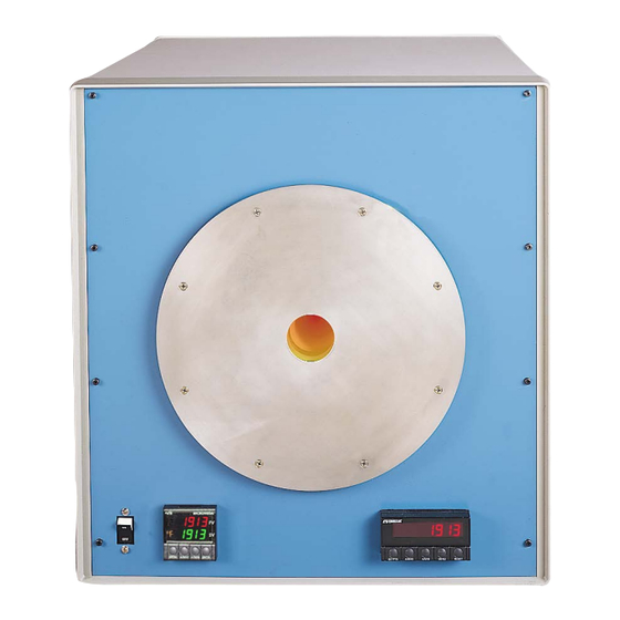
BB705
Very High Temperature
Laboratory Blackbody
Calibration Source
This datasheet has been downloaded from
http://www.digchip.com
at this
page
Table of
Contents
Previous
Page
Next
Page
1
2
3
4
5
Advertisement
Table of Contents
Need help?
Do you have a question about the BB700 Series and is the answer not in the manual?
Ask a question
Questions and answers
Related Manuals for Omega BB700 Series
Test Equipment Omega BB703 User Manual
Blackbody calibrator (20 pages)
Test Equipment omega BB-4A User Manual
(24 pages)
Test Equipment Omega BB-4A Quick Start
Blackbody calibrator (2 pages)
Test Equipment Omega BB701 User Manual
(26 pages)
Test Equipment Omega BB701 Quick Start Quide
Blackbody calibrator 230 vac model only (2 pages)
Test Equipment Omega BB702 User Manual
Blackbody calibrator (24 pages)
Test Equipment Omega BB705 User Manual
Very high temperature laboratory blackbody calibration source (26 pages)
Test Equipment Omega DPG4000 User Manual
Digital test gauge (21 pages)
Test Equipment Omega DRG-SC-FR Instruction Sheet
Frequency input, field configurable signal conditioner (2 pages)
Test Equipment Omega CL-355A User Manual
Dry-block calibrator (12 pages)
Test Equipment Omega CL3001 User Manual
Lab calibrator (104 pages)
Test Equipment Omega cl310 User Manual
M-4590/1107 (109 pages)
Test Equipment Omega CL300A User Manual
Precision thermocouple calibrator (14 pages)
Test Equipment Omega LAQ-XXXX 104 Instruction Sheet
Green label thinners temperature indicating liquids (2 pages)
Test Equipment Omega CL1600-120VAC Quick Start
Surface probe tester (2 pages)
Test Equipment Omega CL514-PLUS User Manual
Automated rtd calibrator (16 pages)
This manual is also suitable for:
Bb705
Bb705-230
Table of Contents
Print
Rename the bookmark
Delete bookmark?
Delete from my manuals?
Login
Sign In
OR
Sign in with Facebook
Sign in with Google
Upload manual
Upload from disk
Upload from URL


Need help?
Do you have a question about the BB700 Series and is the answer not in the manual?
Questions and answers