Table of Contents
Advertisement
Quick Links
Operator's Manual
Circulator
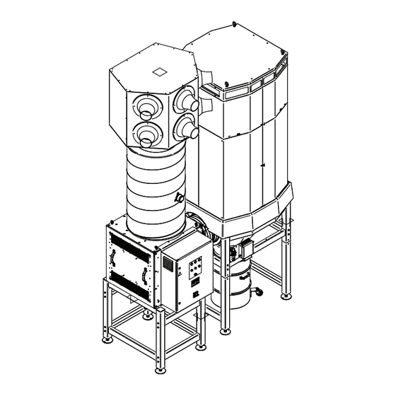
STANDARD (TALL HEIGHT)
OPTION-1 (MEDIUM HEIGHT)
Register your machine:
www.lincolnelectric.com/register
Authorized Service and Distributor Locator:
www.lincolnelectric.com/locator
Save for future reference
Date Purchased
Code: (ex: 10859)
Serial: (ex: U1060512345)
IM10518
| Issue D ate Nov-18
© Lincoln Global, Inc. All Rights Reserved.
®
OPTION-2 (SHORT HEIGHT)
For use with machines having Code Numbers:
AD1326-10
Need Help? Call 1.888.935.3877
to talk to a Service Representative
Hours of Operation:
8:00 AM to 6:00 PM (ET) Mon. thru Fri.
After hours?
Use "Ask the Experts" at lincolnelectric.com
A Lincoln Service Representative will contact you
no later than the following business day.
For Service outside the USA:
Email: globalservice@lincolnelectric.com
Advertisement
Table of Contents

Related Manuals for Lincoln Electric Circulator AD1326-10


Summary of Contents for Lincoln Electric Circulator AD1326-10
- Page 1 Operator’s Manual Circulator ® For use with machines having Code Numbers: AD1326-10 STANDARD (TALL HEIGHT) OPTION-1 (MEDIUM HEIGHT) OPTION-2 (SHORT HEIGHT) Need Help? Call 1.888.935.3877 Register your machine: to talk to a Service Representative www.lincolnelectric.com/register Authorized Service and Distributor Locator: Hours of Operation: www.lincolnelectric.com/locator 8:00 AM to 6:00 PM (ET) Mon.
- Page 2 THANK YOU FOR SELECTING A QUALITY PRODUCT BY KEEP YOUR HEAD OUT OF THE FUMES. DON’T get too close to the arc. LINCOLN ELEC TRIC. Use corrective lenses if necessary to stay a reasonable distance away from the arc. READ and obey the Safety Data PLEASE EXAMINE CARTON AND EQUIPMENT FOR Sheet (SDS) and the warning label DAMAGE IMMEDIATELY...
- Page 3 W117.2-1974. A Free copy of “Arc Welding Safety” booklet E205 is available from the Lincoln Electric Company, 2.d. All welders should use the following procedures in order to 22801 St. Clair Avenue, Cleveland, Ohio 44117-1199.
- Page 4 SAFETY ELECTRIC SHOCK ARC RAYS CAN BURN. CAN KILL. 3.a. The electrode and work (or ground) circuits are 4.a. Use a shield with the proper filter and cover plates to protect your electrically “hot” when the welder is on. Do eyes from sparks and the rays of the arc when welding or not touch these “hot”...
- Page 5 SAFETY WELDING AND CUTTING CYLINDER MAY EXPLODE IF SPARKS CAN CAUSE DAMAGED. FIRE OR EXPLOSION. 7.a. Use only compressed gas cylinders containing the correct shielding gas for the process used 6.a. Remove fire hazards from the welding area. If and properly operating regulators designed for this is not possible, cover them to prevent the welding sparks the gas and pressure used.
-
Page 6: Table Of Contents
CIRCULATOR ® INSTALLATION .............................SECTION A TECHNICAL SPECIFICATIONS ............................A-1 SELECT SUITABLE LOCATION.............................A-2 ENVIRONMENTAL AREA .............................A-2 STACKING ................................A-2 TILTING ................................A-2 LIFTING ................................A-2 GENERAL DESCRIPTION.............................A-2 UNCRATING ................................A-2 HARDWARE OVERVIEW: .............................A-3 TOOLS NEEDED .................................A-3 HARDWARE UNCRATING: ............................A-3 CONNECTION OF FILTER BASE TO FRAME .........................A-3 CONNECTING AIR INLET TO FILTER BASE........................A-3 FAN BASE ASSEMBLY..............................A-4 CONNECTION OF FAN UNIT TO THE LEG BASE. - Page 7 CIRCULATOR ® INSTALLATION TECHNICAL SPECIFICATIONS CIRCULATOR INPUT MAKE/MODEL DESCRIPTION INPUT VOLTAGE NOMINAL CURRENT +/- 10% (MAX.) AD1326-10 Circulator 380-480V/3~/50-60Hz 13.9A PHYSICAL DIMENSIONS HEIGHT WIDTH DEPTH WEIGHT 207.1 in. 86.4 in. 52.2 in. 1764 lbs. 5260 mm 2195 mm 1326 mm 800 kg.
-
Page 8: Installation
CIRCULATOR ® INSTALLATION INSTALLATION GENERAL DESCRIPTION Safety Precautions The CIRCULATOR is a free-standing general filtration system that Read entire installation section before starting prevents accumulation of welding fume by continuous filtration of installation. polluted air. It consists of a central filter unit, a fan in a sound absorbing case, an outlet unit with adjustable outlet nozzles, a WARNING silencer and a control panel with variable frequency drive and... -
Page 9: Hardware Overview
CIRCULATOR ® INSTALLATION HARDWARE OVERVIEW: TOOLS NEEDED A. Outlet unit with 6 adjustable nozzles 9/16" SOCKET WRENCH B. Duct 20 inches (508mm diameter) 9/16" OPEN END WRENCH C. Silencer #5/16 SOCKET WRENCH D. Fan Miscellaneous Hand Tools E. System Control Panel Ladder/Lift F. -
Page 10: Connecting Air Inlet To Filter Base
CIRCULATOR ® INSTALLATION CONNECTING AIR INLET TO FILTER BASE CONNECTION OF FAN UNIT TO THE LEG BASE. 1) Lift the air inlet module with the eye bolts using a crane, align & Carefully move the fan assembly including Silencer & Control place it above the filter housing. -
Page 11: Connecting Outlet Unit
CIRCULATOR ® INSTALLATION 3) Remove the straps & slowly drag down the bracket assembly, place the round piece sitting flush with Silencer top surface. See CONNECTING OUTLET UNIT Figure A.10 1) Carefully lift the assembled Outlet without cutting the Straps on FIGURE A.10 the Holding bracket. -
Page 12: Particulate Collection Drum
CIRCULATOR ® INSTALLATION INSTALL PRESSURE SENSOR AND PITOT TUBE PARTICULATE COLLECTION DRUM 1) Drill 1/4" inch hole in the duct pipe 2 - 3" above the Duct 1. Mount the flexible duct connector onto the drum flange and Bracket. tighten the adjustable clamps using a slot head screwdriver. See Figure A.13. -
Page 13: Option-1 (Medium Height) Installation
CIRCULATOR ® INSTALLATION OPTION-1 (MEDIUM HEIGHT) INSTALLATION INSTALL PRESSURE SENSOR AND PITOT TUBE 1) Follow the same installation procedure as mentioned in the 1) Drill 1/4" inch hole in the duct pipe 10-12" above the Silencer previous pages. 2) Insert Pitot tube & secure it with sheet metal screws (not shown) 2) Cut to length the 20”... -
Page 14: Option-2 (Short Height) Installation
CIRCULATOR ® INSTALLATION OPTION-2 (SHORT HEIGHT) INSTALLATION INSTALL PRESSURE SENSOR AND PITOT TUBE 1) Follow the same installation procedure as mentioned in the 1) Drill 1/4" inch hole in the duct pipe 4" above the Silencer previous pages. 2) Insert Pitot tube & secure it with sheet metal screws (not shown) 3) Install Differential Pressure Sensor on silencer 20"... -
Page 15: Operation
CIRCULATOR ® OPERATION OPERATION INPUT VOLTAGE GRAPHIC SYMBOLS THAT APPEAR INPUT CURRENT ON THIS MACHINE OR IN THIS MANUAL PROTECTIVE GROUND INPUT POWER WARNING or CAUTION Documentation must be con- sulted in all cases where this symbol is displayed. Explosion CIRCUIT BREAKER Dangerous Voltage INPUT POWER... -
Page 16: Controls / Indicator Lights
CIRCULATOR ® OPERATION TIME CONTROLLED OPERATION CONTROL 1. Turn on the main switch. See Figure B.1. The system is designed to run in automatic mode. In this time- controlled operation, the system will start and stop automatically 2. Wait approx. 10 seconds for the system to initialize. at the preset days and times. - Page 17 CIRCULATOR ® OPERATION ENGLISH SAFETY DISPLAY PLC 3A.1 Display WARNING The PLC display looks as follows. Prevent exposure of system control panel to welding or grinding sparks. DISPLAY SYSTEM CONTROL PANEL 2A.1 Display The display of the system control panel looks as follows. POWER ON SYSTEM FAILURE FAN RUNNING...
-
Page 18: Screen Display At Different Modes
CIRCULATOR ® OPERATION times and press ENTER or the ► key. Default timer settings of Monday through Friday ON at 7am OFF at SCREEN DISPLAy AT DIFFERENT MODES 5pm. NOTE: Default times are all dashes on Timer 2, 3 1) When the Unit is Off display will show the current and 4 representing no time is set &... -
Page 19: Offline Cleaning Set Point
CIRCULATOR ® OPERATION OFFLINE CLEANING SET POINT TIME ZONE SETTINGS 1. Unit will start off line cleaning when the filter differen- 1. From LOGO! Settings menu select Setup using ▼ keys and press ENTER or the ► key. tial pressure become greater that On Value and unit is off line for one and half hours. -
Page 20: Automatic System Start-Up
CIRCULATOR ® OPERATION AUTOMATIC SySTEM START-UP 1. Follow Set Weekly Timer procedure. ATTENTION • Do NOT turn off the main switch. • Make sure power supply and com- pressed air are available after working hours. OVERTIME SySTEM START-UP 1. Press MANUAL START. a. - Page 21 CIRCULATOR ® OPERATION * THIS OPERATION PARAMETERS ARE APPLICABLE ONLY FOR THE PANEL WITH LOGO! TD DISPLAY ENGLISH SAFETY DISPLAY PLC 3B.1 Display WARNING The PLC display looks as follows. Prevent exposure of system control panel to welding or grinding sparks. DISPLAY SYSTEM CONTROL PANEL 2B.1 Display The display of the system control panel looks as follows.
-
Page 22: Plc Start-Up Process - Logo! Td Only Menu
CIRCULATOR ® OPERATION The display shows: The display shows: Stop Set Param >Set.. Prg Name Press OK. 11 Press to select the applicable time zone. Press OK. On the Set menu, select ‘Menu Lang’: Press Press OK. The display shows (assuming you have set European time): Press to select the language of your choice. - Page 23 CIRCULATOR ® OPERATION MENU NAVIGATION PRESS DOWN ARROW AND ESC TO SETTINGS ->Stop Set Param Msg Config Stop Prg -> Stop ->No ->Yes ->Set Param Timer 1 2 Timer 1 3 Timer 1 4 Timer 1 1 D=MTWTF_ _ D=MTWTF_ _ Pulse ON/OFF D=MTWTF_ _ ON=08:00...
-
Page 24: Outlet Nozzles
CIRCULATOR ® OPERATION OUTLET NOZZLES To optimize system performance of the CIRCULATOR, position the nozzles and regulate the air flow as follows: • Direct the nozzles at the welding fume layer without obstruction. • Direct the nozzles to the section of the facility where the highest concentration of welding fume occurs. - Page 25 CIRCULATOR ® OPERATION FIGURE B.2 - ADJUSTABLE NOZZLE POSITIONING Welding fume is mixed Preferred at source, optimum dilution Concentration of welding Not Recommended fume instead of dilution Preferred Pref red Example position of two systems Dilution/filtration of a ✓ specific section of the facility Preferred B-11...
- Page 26 CIRCULATOR ® OPERATION FIGURE B.3 - VELOCITY GRAPH (m/s) (m/s) 0,25 V T = final velocity of throw V F = velocity of outlet nozzle L T = throw at VT q v = air volume per nozzle 7 8 1000 1500 2500 2000...
-
Page 27: Maintenance
MAINTENANCE MAINTENANCE SCHEDULE AUTOMATIC FILTER CLEANING NOTE: * REQUIRES Lincoln Electric factory autho- rized service technician. Each time the system is switched off after having been run for at least 1hr 30 min, an automatic cleaning cycle will take place. -
Page 28: Motor/Fan Housing
CIRCULATOR ® MAINTENANCE MOTOR/FAN HOUSING (Sound Absorbing Enclosure) • Check the integrity of the fan housing (sound absorbing box) and tighten all bolts and screws if necessary. • Verify unit is level and adjust if necessary. • Clean housing (sound absorbing enclosure) with a non- aggressive detergent. -
Page 29: Replacing The Filters
CIRCULATOR ® MAINTENANCE How To Replace Filters REPLACING THE FILTERS 1. Disconnect input power and the compressed air connection. 2. Using 9/16" nut driver remove the nuts securing the connecting WARNING Brackets 3. Using 9/16" nut driver Loosen the nuts at holding bracket side. •... -
Page 30: Troubleshooting
Service Facility. IIf you do not understand or are unable to perform the Recommended Course of Action safely, contact the Lincoln Electric Automation Division: 22221 St. Clair Ave. Cleveland, Ohio 44117-1199 U.S.A. Phone: 1-888-935-3878 option 4 If the equipment is used in a manner not specified by the manufacturer, the protection provided by the equipment may be impaired. - Page 31 CIRCULATOR ® TROUBLESHOOTING PROBLEM POSSIBLE AREAS OF RECOMMENDED COURSE OF ACTION (SYMPTOMS) MISADJUSTMENT(S) When the “Start Button” is 1. Make sure the correct input power is being pressed the system will not start. 2. Check if power light is ON (White Light). 3.
-
Page 32: Diagrams
CIRCULATOR ® DIAGRAMS FIGURE F.1 BLOCK LOGIC DIAGRAM 3 PHASE OUTLET CONTROL 20-60 HZ SILENCER DUCT MOTOR/ UNIT PANEL AIR FILTER 24 VAC SIGNAL SOLENOID FILTER PRESSURE CONTROL AIR FILTER PRESSURE TRANSMITTER DIFFERENTIAL LINES INLET MONITOR EXTERNAL COMPRESSED AIR SUPPLY... - Page 33 FLA: 14A SHORT CIRCUIT CURRENT : 50kA RMS SYMMETRICAL, 480V MAXIMUM CONNECTION E SOLENOID CONNECTION D THE LINCOLN ELECTRIC COMPANY World's Leader in Welding and Cutting Products A.03 Sales and Service through Subsidiaries and Distributors Worldwide Cleveland, Ohio 44117-1199 U.S.A. S31228-234PRINT...
- Page 34 CIRCULATOR ® DIAGRAMS...
- Page 35 CIRCULATOR ® DIAGRAMS...
- Page 36 CIRCULATOR ® DIAGRAMS...
- Page 37 CIRCULATOR ® DIAGRAMS...
- Page 38 CIRCULATOR ® DIAGRAMS...
- Page 39 CIRCULATOR ® DIAGRAMS...
- Page 40 CIRCULATOR ® DIAGRAMS...
- Page 41 CIRCULATOR ® DIAGRAMS (86.37) 52.16 207.11 139.80 78.99 STANDARD (TALL HEIGHT) E-10...
- Page 42 CIRCULATOR ® DIAGRAMS 86.37 52.16 172.24 139.80 78.99 OPTION-1 (MEDIUM HEIGHT) E-11...
- Page 43 CIRCULATOR ® DIAGRAMS 96.55 52.16 156.80 139.80 89.20 OPTION-2 (SHORT HEIGHT) E-12...
- Page 44 This page intentionally left blank.
- Page 45 This page intentionally left blank.
- Page 46 WARNING Do not touch electrically live parts or Keep flammable materials away. Wear eye, ear and body protection. electrode with skin or wet clothing. Insulate yourself from work and AVISO DE ground. Spanish PRECAuCION No toque las partes o los electrodos Mantenga el material combustible Protéjase los ojos, los oídos y el bajo carga con la piel o ropa moja-...
- Page 47 WARNING Keep your head out of fumes. Turn power off before servicing. Do not operate with panel open or Use ventilation or exhaust to guards off. remove fumes from breathing zone. AVISO DE Spanish PRECAuCION Los humos fuera de la zona de res- Desconectar el cable de ali- No operar con panel abierto o piración.
- Page 48 TLV limits. Lincoln Electric is not in a position to warrant or guarantee such advice, and assumes no liability, with respect to such information or advice. We expressly disclaim any warranty of any kind, including any warranty of fitness for any customer’s particular...
Need help?
Do you have a question about the Circulator AD1326-10 and is the answer not in the manual?
Questions and answers