
Subscribe to Our Youtube Channel
Related Manuals for SOLINTEG INTEG O OGS-1.5K


Summary of Contents for SOLINTEG INTEG O OGS-1.5K
- Page 1 I nteg On-GRID I nverter S ol int e g OGS- 1.5 / 2.5 / 3 .3 K Quick Installation Guide EN GL ISH VE R SION...
-
Page 2: Installation Location
Monitoring device (1pcs) User Manual PE terminal (1pcs) User guide Solinteg RMK with 1 CT (1pcs) or 1CT (1pcs)** *There are two versions of the COM2 connector, please select the appropriate version according to the order requirements. **Optional Installation Location... -
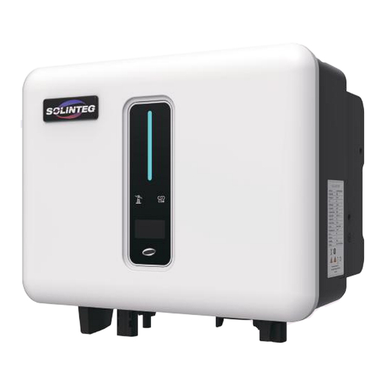
Page 3: Mounting Inverter
Part 1 Installation Mark the Position and Drill Holes Fix Wall Bracket Mounting Inverter Grounding Terminal Connection 2 Electrical Connection Electrical Wiring Diagram LOADS UTILITY GRID UTILITY METER 002456 FOR BILLING PURPOSES Electrical Wiring Diagram... - Page 4 LOADS UTILITY GRID 002456 UTILITY METER FOR BILLING PURPOSES SOLINTEG CT Electrical wiring diagram of export limit LOADS UTILITY GRID SOLINTEG UTILITY METER 002456 FOR BILLING PURPOSES Electrical wiring diagram of export limit & 24 hours load consumption AC Connection...
- Page 5 ② ③ ④ Monitoring Device Installation If the inverter is connected to the Solinteg Datalogger and RMK, the Monitoring Device does not need to be connected, and refer to the Datalogger or RMK manual to connect it to the internet.
- Page 6 Communicate with inverter RS485-2 Reserved RMK terminals definition Communication connection (Basic version) Definition Function Location hole RS485-A1 RS485-A2 Communicate with Solinteg RMK or Datalogger. RS485-A1 RS485-A2 Reserved Wire Diameter 7~11mm Cross-sectional Area 0.5~1.5mm 20mm Cable Gland Threaded Sleeve Threaded Sleeve Terminal Head ①...
- Page 7 ④ ⑤ Communication connection (Extended version) Function RS 485 A2 RS 485 B2 Fast stop + Fast stop - Dipswitch-1 DRED resistor dipswitch between15(COM D/0) and 16(REF D/0) Dipswitch-2 120Ω terminating resistor dipswitch between RS 485 A1 and RS 485 B1 CT-S1 CT-S2 RS 485 A1...
- Page 8 Wire Diameter 3.5~6mm Cross-sectional Area 0.5~1.5mm 55mm ③ ④ ⑤ ⑥ Click ⑦ ⑧ CT installation (Optional) S1(Red) S2(Yellow) The direction of the arrow is consistent with Click the direction of the arrow ⑨ inside the CT.
- Page 9 2 WiFi Module Configuration Guide Prepare a laptop or Searching for the Smartphone and turn corresponding WLAN on the WLAN in the WLAN connection. connection list “WIFI-AP********” (*represents the last 8 numbers of the inverter SN), and tap connect. Open the browser and Tap“Scan”,A list of enter 10.10.100.254.
- Page 10 If connected successfully “Connec- tion succeeded” will displayed. After successful configure, the indicator status of WIFI module will be steady on. 3 LAN Module Configuration Guide If DHCP is enabled on the router, the LAN module does not need to be configured. Otherwise, the LAN module will need to be configured on inverter screen.
- Page 11 Grid Indicator Always on Green Always on Communica- mally. tion Indicator Green Flashing or Solinteg RMK through RS485. Display Button 5.2 Monitoring Device Indicator Status Description Connection abnormal Communicate with the server normally Always On Slow flashing The monitoring device is not connected to the router or is not connected to the base station.
- Page 12 w w w.s ol integ .com...
Need help?
Do you have a question about the INTEG O OGS-1.5K and is the answer not in the manual?
Questions and answers