
Subscribe to Our Youtube Channel
Related Manuals for Speco H40HR


Summary of Contents for Speco H40HR
- Page 1 H40HR (40 Channel) User Manual Version 1.0 Features and specifications are subject to change, please check www.specotech.com for firmware updates.
-
Page 2: Table Of Contents
Notes& Contents DVR User Manual Notes Please read this user manual carefully to ensure that you can use the device correctly and safely. There may be several technical or printing errors in this manual. The contents of this manual are subject to change without notice. ... - Page 3 Notes& Contents DVR User Manual 6.2 Preset Setting ........................................26 6.3 Cruise Setting ........................................27 6.4 PTZ Protocol Settings ....................................... 28 Record & Disk Management ..................................29 7.1 Record Configuration ....................................... 29 7.1.1 Mode Configuration ..................................... 29 7.1.2 Schedule Settings ....................................30 7.1.3 Advanced Configuration ..................................
- Page 4 Notes& Contents DVR User Manual 10.3.2 Edit Permission Group ..................................58 10.4 Block and Allow List ....................................... 58 10.5 Preview On Logout ......................................58 10.6 Password Security ......................................59 10.7 View Online User ......................................59 Device Management ....................................60 11.1 Network Configuration ....................................60 11.1.1 TCP/IP Configuration ..................................
-
Page 5: Introduction
Introduction DVR User Manual 1 Introduction 1.1 Welcome Thank you for purchasing this DVR. If technical assistance is needed, please contact Speco Technologies Technical Support. Phone: 1-800-645-5516 option 3 Email: techsupport@specotech.com 1.2 Features Basic Functions Supports network device access including IP camera/dome and the third-party IP cameras ... - Page 6 Introduction DVR User Manual Record Playback Supports time scale operation in quick playback and the playback date and time can be set randomly by scrolling the mouse; the time interval of the time scale can be zoomed Supports record searching by time slice/time/event/tag ...
-
Page 7: Front Panel Descriptions
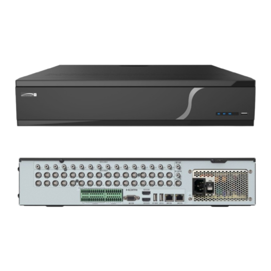
1.4 Rear Panel Descriptions To quickly get started, connect the following to your recorder in the following order, please refer to Figure 1-2 (H40HR shown for reference). 1. Connect analog cameras to the video input ports (BNC) of the recorder. -
Page 8: Basic Operation Guide
Basic Operation Guide DVR User Manual 2 Basic Operation Guide 2.1 Startup & Shutdown Please make sure all the connections are done properly before you power on the unit. Proper startup and shutdown are crucial to extend the life of your device. -
Page 9: Mouse Control
Basic Operation Guide DVR User Manual Button Function Switch off—to stop the device Power Button Record Button To start recording -/-- /0-9 Input number or choose camera Fn1 Button Unavailable temporarily Multi Button To choose multi-screen display mode Next Button To switch the live image To go to sequence view mode Audio... -
Page 10: Common Button Operation
Basic Operation Guide DVR User Manual The system includes two input boxes. Refer to the above pictures. The left box is the number input box, and the right box is the input box which provides inputs of numbers, letters, and punctuation characters. The introductions of keys on the input boxes are shown below. Button Meaning Button... -
Page 11: Ez Setup & Main Interface
EZ Setup & Main Interface DVR User Manual 3 EZ Setup & Main Interface 3.1 EZ Setup The disk icons will be shown on the top of the startup interface. You can view the number and status of each disk quickly and conveniently through these icons ( : no disk;... - Page 12 EZ Setup & Main Interface DVR User Manual ③ Network Settings. Check “Obtain an IP address automatically” and “Obtain DNS automatically” to get the IP address and DNS automatically (the DHCP function of the router in the same LAN should also be enabled), or manually enter them. Enter the HTTP port, RTSP port and Server port (please see Port Configuration for details).
- Page 13 EZ Setup & Main Interface DVR User Manual Click to edit the searched IP camera as shown on the below left. Enter the new IP address, subnet mask, gateway, username, and the password of the camera. You can check “Sync to IPC” to modify the IP address of the IPC via different network segments for being in the same network segment with the DVR.
-
Page 14: Main Interface
⑨ QRCode. Enable the NAT function in the interface or set it in the network configuration after exiting the wizard (please refer to NAT Configuration for details). You can scan the QRCode through the Speco Blue App available for iOS and Android to view your cameras easily and securely. -
Page 15: Setup Panel
EZ Setup & Main Interface DVR User Manual Button Meaning Click to set the default playback time before starting instant playback (Instant Playback) or going to the playback interface for playback operations (Playback Interface Introduction); click to go to the playback interface. For instance, if you choose “5 minutes ago”... -
Page 16: Main Functions
EZ Setup & Main Interface DVR User Manual The setup panel includes seven modules. Each module provides some function entries with links for convenient operation. Here we take Camera module as an example. The Camera module provides convenient links such as “Add Camera”, “Edit Camera”, “Image Settings”, “Motion”, “Intelligent Analytics”... - Page 17 EZ Setup & Main Interface DVR User Manual The module covers the functions such as TCP/IP, DDNS, Port, E-mail, and Network Status and so on. Please see Network Configuration for details. Account and Authority The module covers the functions such as Account Management (see Account Management for details) and Permission Management (see Permission Management for details) and so on.
-
Page 18: Camera Management
Camera Management DVR User Manual 4 Camera Management 4.1 Camera Signal Click StartSettingsCameraManage CameraCamera Signal to go to the interface as shown below. This product supports analog signal switching to IP signal, which means decreasing (or increasing) the number of analog channels, accordingly increasing (or decreasing) the number of IP channels with the total channels unchanged. -
Page 19: Edit Camera
Camera Management DVR User Manual Quickly Add Check the cameras and then click “Add” to add cameras. Click to edit the camera’s IP address, username, and password and so on. Click “Default Password” to set the default username and password of each camera. Add Manually ... - Page 20 Camera Management DVR User Manual passwords can be modified at the same time). Click to upgrade an online IPC ( or click in the “Upgrade” header line and then click “IPC Batch Upgrade” to upgrade a batch of IPCs), select the device which stores the upgrade file in the “Device Name” item of the popup window and the upgrade file in the list(you should select the upgrade IPC model in the window if a batch of IPCs’...
-
Page 21: Live View Introduction
Live View Introduction DVR User Manual 5 Live View Introduction 5.1 Live View Interface Introduction The connected analog camera will be added automatically in the live view interface for previewing. You should add camera first after logging on to the system (see Add Camera for details). Refer to the interface as shown below, drag one camera in the preview window to another window for camera window exchanging. -
Page 22: View Mode
Live View Introduction DVR User Manual 5.2 View Mode 5.2.1 Display Mode Set different screen modes and cameras’ display sequences as needed and then save the display modes classified by surveillance areas, priorities and so on. Refer to the picture below. Double click one display mode in the display mode list to view the live images in this mode. Add Display Mode ... -
Page 23: Quick Sequence View
Live View Introduction DVR User Manual Click “Customize Display Modes” tab in the live preview interface and then select one display mode in the list. Click to edit the display mode name; click to delete the display mode. 5.2.2 Quick Sequence View You can start quick sequence view if the scheme has not been created. -
Page 24: Image Configuration
Live View Introduction DVR User Manual dwell time and click “Apply” to start playing the schemes in sequence in output 2. 5.3 Image Configuration 5.3.1 OSD Settings Click StartSettingsCameraImageOSD Settings to go to the interface as shown below. Select the camera, enter the camera name (or double click the camera name in the camera list to change the camera name), enable or disable the name and time OSDs (if enabled, drag the red name and time OSDs directly in the image view area to change the OSDs’... -
Page 25: Water Mark Settings
Live View Introduction DVR User Manual 5.3.4 Water Mark Settings Click StartSettingsCameraImageWater Mark Settings to go to the interface as shown below. Select the camera and enable water mark and then enter the water mark information. Click “Apply” to save the settings. 5.3.5 Image Adjustment Go to the live view interface and then click button on the tool bar under the camera window to go to the image adjustment interface. - Page 26 Live View Introduction DVR User Manual Select the camera and then click “Image Adjustment” to go to the image adjustment tab. Refer to the above picture. Drag the slider to set the camera’s brightness, contrast, saturation, and hue value. Check sharpens, wide dynamic and denoise and then drag the slider to set the value. Click “Default”...
- Page 27 Live View Introduction DVR User Manual Button/Parameter Meaning Click to focus instantly. Day/night mode If checked, the lens will focus automatically when the camera is switching switch autofocus day/night mode. It is the time interval when camera lens is auto-focusing. The interval can Time Interval be set in the drop-down list.
-
Page 28: Ptz
DVR User Manual 6 PTZ 6.1 PTZ Control Interface Introduction You can control the IP dome or PTZ which connects to the IP camera for PTZ control. Click on the tool bar at the bottom of the live preview window to go to the PTZ control interface as shown below. Introductions of the buttons on the bottom right of the interface: Button Meaning... - Page 29 DVR User Manual Refer to the picture as shown below. Drag the mouse from C to D to get a green rectangle and the rectangle area will be zoomed out. Advanced 3D Control Double click the left button of the mouse on any area of the camera image and then the image size will be doubled and centered on the clicked point.
-
Page 30: Preset Setting
DVR User Manual Button Meaning Click to change the menu mode or increase the menu value. Click to go to the previous menu. Click to go to the next menu. Preset Setting Click “Preset” to go to preset operation tab and then click “Add” button to display a window as shown below. Select the preset and then enter the preset name in the window;... -
Page 31: Cruise Setting
DVR User Manual Add preset Select camera and then click “Add” button to add preset; or click in the camera list on the right side of the interface to display the preset information of the dome and then click to add preset. -
Page 32: Ptz Protocol Settings
DVR User Manual to add preset to the cruise. Click to edit the preset. Click to delete the preset from the cruise. Click one preset in the preset list and then click to move down the preset and click to move up the preset. Click to start the cruise and click to stop it. -
Page 33: Record & Disk Management
Record & Disk Management DVR User Manual 7 Record & Disk Management 7.1 Record Configuration 7.1.1 Mode Configuration Please format the HDDs before recording (refer to Disk Management for details). Click StartSettingsRecordMode Settings to go to the mode settings interface. You can set the record time under the “Manual Record Settings” and then click “Apply” to save the settings. There are two record modes: auto mode and scheduled mode. -
Page 34: Schedule Settings
Record & Disk Management DVR User Manual Video Encode: the available options will be H.265 and H.264 if the connected IP camera supports H.265, or the option will be H.264 only. Resolution: the higher the resolution is, the clearer the image is. FPS: the higher the frame rate is, the more fluent the video is. - Page 35 Record & Disk Management DVR User Manual Click “Add” to add a new schedule. Refer to the picture below. Set the schedule name and schedule time and then click “Add” to save the schedule. You can set a day schedule or week schedule. : add button;...
-
Page 36: Advanced Configuration
Record & Disk Management DVR User Manual Click “All” to set all week recording; click “Reverse” to swap the selected and unselected time in a week; click “Clear All” to clear all the selected area in a week. 7.1.3 Advanced Configuration Click StartSettingsRecordAdvanced to go to the following interface. -
Page 37: Record Mode
Record & Disk Management DVR User Manual 7.3 Record Mode 7.3.1 Manual Recording Method One: Click on the tool bar at the bottom of the live view interface to enable recording of the camera. Method Two: Go to the live view interface and then click the right-click menu “Manually Record On” in the camera window or click on the tool bar under the camera window to start recording. - Page 38 Record & Disk Management DVR User Manual ① Click “Change Encrypt”. ② Enter the username and password used to log in the DVR. This user shall have permission to access disk management. ③ Check the disk you want to decrypt and then empty the password. ④...
-
Page 39: Storage Mode Configuration
Record & Disk Management DVR User Manual e. Select a hot spare. In the physical disk interface, select the disk that is not in the array and click as shown in the following pictures. RAID Rebuilding If one of your disks is broken, the disk indicator on the front panel will turn red. Of course, a warning tip will pop up if the relevant HDD exception alarm is set. -
Page 40: View Disk And S.m.a.r.t. Information
Record & Disk Management DVR User Manual Each group can add disks and cameras from other groups. Each disk and camera can only be added into one group. Select a disk group and then click in the disk or camera row to pop up a window. Check the disks or cameras in the window and then click “Add”. Note: Each HDD can only exist in one group. -
Page 41: Playback & Backup
General Event Management DVR User Manual 8 Playback & Backup 8.1 Instant Playback Click on the tool bar at the bottom of the preview camera window to play back the record (click on the tool bar at the bottom of the live view interface to set the default playback time). - Page 42 General Event Management DVR User Manual The added cameras will playback their records in the playback interface automatically. You can also add the playback camera manually. Click in the playback window to pop up the “Add Camera” window. Check the cameras in the window and then click “Add” to add playback camera. The system supports a maximum of 16 synchronous playback cameras.
-
Page 43: Smart Playback
General Event Management DVR User Manual Move tool. Click to move the tool bar anywhere. Click to enable audio. You can listen to the camera audio by Enable Audio enabling audio. Snapshot Click to snap. Click to go to the zoom in interface. The zoom in interface is like that of the camera window in the live view interface. -
Page 44: Record Search, Playback &Export
General Event Management DVR User Manual Smart Playback by Drawing Rectangle Click and draw a rectangle in the desired area. Then the system will automatically search the record files of this area. The cyan blocks indicate that there are intelligent recording files. Move the cursor to such block and click to play the record. Smart Playback by Drawing Line ... -
Page 45: Ez Search
“Record Backup” window as shown below. Select the device name, backup format and path and then click “Export” button to start the backup. Speco Blue Player Note: If you back up the record in private format, the system will back up a Speco Blue Player to USB device automatically. The private format record can be played by Speco Blue Player only. -
Page 46: Museum Search
General Event Management DVR User Manual Time Slice Search: Method One: Click “Year”, “Month” or “Day” button under the record time scale to select the time slice mode. In “Day” mode, click on the left/right side of the time scale to view the record of the last/next day; click “Minute” in the “Picture” option under the time scale to select “Minute”... -
Page 47: Event Search
General Event Management DVR User Manual 8.4.4 Event Search ① Click StartSearch and ExportEvent Search to go to “Event Search” tab as shown below. ② Check the event type in the interface as required. ③ Click to set the start time and end time on the top left of the interface. ④... -
Page 48: Snapshots
General Event Management DVR User Manual Click in the interface to play the record. Click to edit the tag name. Click to delete the tag. 8.4.6 Snapshots Click StartSearch and ExportSnapshots to go to “Snapshots” tab. The system will display all the captured images automatically in the list. Click to delete the image. -
Page 49: Motion Alarm
General Event Management DVR User Manual ② Select schedule and the alarm type (NO or NC) according to trigger type of the sensor. ③ Enable the sensor alarm of each camera. ④ Check the “Duration”, “Record”, “Snapshot”, “Push”, “Alarm-out” and “Preset” and enable or disable the “Buzzer”, “Pop-up Video”, “Pop-up Message Box”... -
Page 50: Motion Configuration
General Event Management DVR User Manual 9.2.1 Motion Configuration ① Click StartSettingsCameraMotion to go to the following interface. ② Select the camera, enable the motion, and set the sensitivity and duration of the camera. Sensitivity: the higher the value is, the more sensitive it is to motion. You should adjust the value according to the practical conditions since the sensitivity is influenced by color and time (day or night). -
Page 51: Tampering
General Event Management DVR User Manual Missing object: Alarms will be triggered if there are articles missing in the detection area drawn by the users. ③ Select the alarm area. A maximum of 4 alarm areas can be set. ④ Draw the alarm area of the object detection. Refer to the interface as shown above. Check “Draw Area” and then click around the area where you want to set as the alarm area in the image (the alarm area should be a closed area). -
Page 52: Tripwire
General Event Management DVR User Manual ② Select the camera and enable the relevant detection as needed. Scene Change: Alarms will be triggered if the scene of the monitor video has changed. Video Blurred: Alarms will be triggered if the video becomes blurry. Video Color Cast: Alarms will be triggered if the video becomes obscured. -
Page 53: Intrusion Detection
General Event Management DVR User Manual ① Click StartSettingsAlarmIntelligence AlarmTripwire to go to the following interface. ② Enable or disable “Snapshot”, “Push”, “Alarm-out”, “Preset”, “Buzzer”, “Pop-up Video” and “E-mail”. The alarm handling setting of line crossing alarm is like that of the sensor alarm (see Sensor Alarm for details). ③... -
Page 54: Exception Alarm
General Event Management DVR User Manual ② Enable or disable “Snapshot”, “Push”, “Alarm-out”, “Preset”, “Buzzer”, “Pop-up Video” and “E-mail”. The alarm handling setting of intrusion detection alarm is like that of the sensor alarm (see Sensor Alarm for details). ③ Click “Apply” to save the settings. You can click “Intrusion Config” to go to the intrusion detection configuration interface. 9.4 Exception Alarm 9.4.1 IPC Offline Settings ①... -
Page 55: Warning Handling Settings
General Event Management DVR User Manual 9.4.3 Warning Handling Settings ① Click StartSettingsAlarmExceptionWarning Handling Settings to go to the interface as shown below. ② Enable or disable “Push”, “Alarm-out”, “Buzzer”, “Pop-up Message Box” and “E-mail”. The exception handling settings are like that of the sensor alarm (see Sensor Alarm for details). -
Page 56: Buzzer
General Event Management DVR User Manual 9.5.4 Buzzer Click StartSettingsAlarmEvent NotificationBuzzer to go to the buzzer configuration interface. Set the delay time of the buzzer and then click “Apply” to save the setting. You can click “Test” to test the buzzer. 9.5.5 Push Message Click StartSettings... -
Page 57: View Alarm Status
General Event Management DVR User Manual 9.7 View Alarm Status Click StartSettingsAlarmAlarm Status or click on the tool bar at the bottom of the live preview interface to view the alarm status. Click “Clear” to stop the buzzer when the buzzer alarm happens. Click to view the detail information as shown below. - Page 58 General Event Management DVR User Manual If the exception information is more than one page, you can enter the number in the box and then click to jump to the specified page. Click to view the exception alarm information in the previous/next page.
-
Page 59: Account & Permission Management
Account & Permission Management DVR User Manual 10 Account & Permission Management 10.1 Account Management Click StartSettingsAccount and AuthorityAccountEdit User to go to the interface as shown below. Area ① displays the user permissions. Area ② displays the user list. Click the user in the list to display its user permissions in area ①. There are three default permission groups (“Administrator”, “Advanced”... -
Page 60: Edit User
Account & Permission Management DVR User Manual 10.1.2 Edit User Click StartSettingsAccount and AuthorityAccountEdit User and then click in the user list or double click the user to edit the user information. Click to delete the user (the user admin cannot be deleted). Edit Security Question ... -
Page 61: User Login & Logout
Account & Permission Management DVR User Manual 10.2 User Login & Logout Login: Click StartLogin or directly click the preview interface and then select username and enter the password in the popup window. Click “Login” button to log in the system. Logout: Click StartLogout or click StartShutdown to pop up the “Shutdown”... -
Page 62: Edit Permission Group
Account & Permission Management DVR User Manual 10.3.2 Edit Permission Group Go to “Edit Permission Group” interface and then click in the group list to edit the permission group (the operations of the “Edit Permission Group” are like that of the “Add Permission Group”, please see Add Permission Group for details). Click to save the group as another group. -
Page 63: Password Security
Account & Permission Management DVR User Manual 10.6 Password Security Click StartSettingsAccount and AuthoritySecurityPassword Security to go to the following interface. In this interface, you can set the level and expiration time of the password. 10.7 View Online User Click StartSettingsAccount and AuthorityUser Status to view the online user information (you can view the online username, login type, IP address and login time;... -
Page 64: Device Management
Device Management DVR User Manual 11 Device Management 11.1 Network Configuration 11.1.1 TCP/IP Configuration Click StartSettingsNetworkTCP/IP to go to the following interface. Check “Obtain an IPv4 address automatically”, “Obtain an IPv6 address automatically” and “Obtain DNS automatically” to get the network addresses automatically, or manually enter the network addresses. You can modify the MTU value according to the network condition (MTU, Maximum Transmission Unit, can be modified according to network condition for higher network transmission efficiency). - Page 65 Device Management DVR User Manual If you want to access the DVR through a web browser, you should enter IP address plus HTTP port in the address bar of the web browser like http://192.168.11.61:81. HTTPS Port: the default HTTPs port of the DVR is 443. HTTPs provides authentication of the web site and protects user privacy.
-
Page 66: Pppoe Configuration
11.1.4 DDNS Configuration The DDNS is used to control the dynamic IP address through domain name. Speco Technologies provides free DDNS service with US-based servers. You can access the DVR easily if the DDNS is enabled and configured. Click StartSettingsNetworkDDNS to go to the interface as shown below. The default DDNS type will be “specoddns.net”. -
Page 67: Upnp Configuration
Device Management DVR User Manual Click “Edit Recipient” to go to the following interface. Click “Add” and then enter the recipient’s e-mail address and select the schedule (if a schedule is selected, the system will send the alarm email and the recipient will receive it only in the selected schedule time) in the popup window. Click “Add” in the window to add the recipient. You can also change the recipient’s receiving schedule by clicking in the “Schedule”... -
Page 68: 802.1X
QR code number under the QR code. Via Internet Explorer, go to connect.specotech.cloud, input the QR code number, your username and password to login. You can also scan the QRcode through Speco Blue App which is installed on a mobile phone or tablet to log in to the mobile client instantly. 11.1.9 View Network Status Click StartSettingsNetwork... -
Page 69: Date And Time Configuration
Device Management DVR User Manual Device Name: The name of the device. It may display on the client end or CMS that help user to recognize the device remotely. Video Format: Two modes: PAL and NTSC. Select the video format according to the camera. Sequence Automatically: Check it and set “wait time”. -
Page 70: Backup And Restore
Device Management DVR User Manual Note: The file system of the USB mobile device which is used for upgrading, backing up and restoring should be FAT32 format. Flash Upgrade The upgrade steps are as follows: ① Copy the flash upgrade files into the USB storage device. ②... -
Page 71: View System Information
Device Management DVR User Manual Choose the log file in the list and then click “Export” button to export the log file. Click on the “Content” title bar to pop up a menu list. Check contents in the menu list and then the log list will show the checked log contents only. Click to play the video log. -
Page 72: Remote Surveillance
① Enable NAT in the DVR. Refer to NAT Configuration for details. ② Scan the QRCode through the Speco Blue App available for iOS and Android to view your cameras easily and securely. ③ Run the Speco Blue App, go to the “Add Device” interface and then click to scan the QRCode of the DVR (Go to StartSettingsSystemInformationBasic to view the QRCode of the DVR). -
Page 73: Web Remote Control
DVR User Manual PPPoE Access ① Click StartSettingsNetworkPPPoE to go to the “PPPoE” interface. Check “Enable” in the “PPPoE settings” and then enter the username and password you get from your ISP. Click “Apply” to save the settings. ② Click StartSettingsNetworkNetwork Status to view the IP address of the DVR. ③... - Page 74 DVR User Manual Start Preview Select a window in the preview area and then click one online camera on the left panel to preview the camera in the window. You can click the tool bar to view all the cameras. Left Panel Introduction ...
- Page 75 DVR User Manual Right Panel Introduction Click on the right panel to show the panel and click to hide the panel. Click at the bottom of the panel to go to “PTZ” panel. Click to go to “Lens Control”. Click to go to “Operation”...
- Page 76 DVR User Manual Button Meaning Click to view the cruise list and then click the corresponding buttons in the list to start or stop the cruise. Click to play the cruise; click to stop cruise. Plug-in Free Live View Only 4-screen display can be supported for the plug-in free live view.
-
Page 77: Remote Playback
DVR User Manual Click one camera window in the preview area and then click to set the camera’s live view stream and record stream to main stream in manual record mode; click to set the camera’s live view stream and record stream to sub stream. In the sub stream tab, set the resolution, FPS and bitrate and then click “Apply”... -
Page 78: Remote Export
DVR User Manual ① Check the record event types and cameras on the left panel. Set the record date on the calendar beside the time scale. ② Click to search the record data and then click or directly click the time scale to play the record. The operation of the playback time scale is like that of the time scale in the main program of the DVR. -
Page 79: Appendix A Faq
DVR User Manual Appendix A FAQ Q1. Why can’t I find the HDD? Please check the power and SATA data cables of the HDD to make sure they are well connected. For some DVRs with the 1U or small 1U case, the power of the adapter may be not enough for operating them. Please use the power adaptor supplied along with the DVR. - Page 80 with the record data. Uncompress the “Speco Blue Player zip” and then click “Speco Blue Player .exe” to set up Speco Blue Player. After the setup is completed, open Speco Blue player and then click “Open Folder” button in the middle of the interface to select the record data. Refer to Fig 9-1.
- Page 81 DVR User Manual If you select the AVI format when backing up a record by DVR, the record backup data can be played by the video player which supports this format. Record backed up through web. The record can only be backed up with AVI format through the web. The record can be backed up to PC and played by the video player which supports this format.
-
Page 82: Appendix B Calculate Recording Capacity
Calculate Recording Capacity DVR User Manual Appendix B Calculate Recording Capacity The recording capacity is mainly up to the record resolution, record stream and bitrate. Different image quality parameters decide different disk capacity occupation in equal times. The bigger the record resolution, record stream and record bitrate is, the more disk capacity is taken up in equal times. - Page 83 Model: H40HR Federal Communications Commission (FCC) Statements This device complies with Part 15 of the FCC Rules. Operation is subject to the following two conditions: (1) This device may not cause harmful interference, and (2) This device must accept any interference received, including interference that may cause undesired operation.
Need help?
Do you have a question about the H40HR and is the answer not in the manual?
Questions and answers