Table of Contents
Advertisement
Quick Links
Speco Technologies
4 Channel H.264 Mobile DVR
User Manual
Speco Technologies is constantly developing product improvements
We reserve the right to modify product design and specifications without notice and without incurring any obligation
Rev. 3/17/10
Speco Technologies
200 New Highway, Amityville, NY 11701
1-800-645-5516
www.specotech.com
Advertisement
Table of Contents

Subscribe to Our Youtube Channel
Related Manuals for Speco DVRM42


Summary of Contents for Speco DVRM42
-
Page 1: User Manual
Speco Technologies 4 Channel H.264 Mobile DVR User Manual Speco Technologies is constantly developing product improvements We reserve the right to modify product design and specifications without notice and without incurring any obligation Rev. 3/17/10 Speco Technologies 200 New Highway, Amityville, NY 11701 1-800-645-5516 www.specotech.com... -
Page 2: Table Of Contents
Contents FEATURES AND SPECIFICATIONS ........................4 Features ................................4 Specifications..............................5 OVERVIEW & CONTROLS ..........................8 Front Panel ..............................8 Rear View ................................ 9 Remote Control ............................. 10 MAIN SCREEN ..............................11 MAIN MENU ............................... 12 Quick Setup Menu ............................12 4.1.1 Quick Setup .............................. - Page 3 4.4.3 Event Check ............................. 23 4.4.4 Event indication ............................24 4.4.5 Sensor Input Select ..........................24 4.4.6 Relay Output ............................24 4.4.7 GPS ................................25 SYSTEM ................................. 26 4.5.1 Storage ..............................26 4.5.1.1 Storage Configuration ..........................27 4.5.1.2 SD Card Initialize ............................. 27 4.5.2 Clock ................................
- Page 4 WIRELESS ............................... 48 INSTALLATION ..............................48 DVR ................................48 Media Viewer ..............................48 Mobile Manager ............................. 48 DVR SETTING ..............................48 Front Panel ..............................48 Air Card Connection ............................. 48 Operation ............................... 49 7.3.1 DVR Menu Setting ..........................49 7.3.1.1 Auto/Manual .............................
-
Page 5: Features And Specifications
FEATURES AND SPECIFICATIONS Features • H.264 Compression algorithm • Max 120 FPS (CIF) /60 FPS (D1) recording in NTSC • Pentaplex Operation • SD Card Storage • Expandable up to 4 SD memory cards • 1 Channel Synchronized Audio • 4 Levels of image quality settings •... -
Page 6: Specifications
Specifications VIDEO Speco Technologies Mobile DVR Video Input 4CH (BNC/RCA) Input Level 1.0Vp-p±10% Composite, 75Ω Balanced Loop Through Output Not supported Video Standard NTSC, PAL, AUTO 1.0 Vp-p Composite, 75Ω Balanced Main Monitor Output Analog Spot Monitor Output 1.0 Vp-p Composite, 75Ω Balanced Camera Name Max. - Page 7 Internal Storage SD CARD { SD Card } SD Bay Interface 4 SD card EXT Bay (Optional) Searching & Playback Searching Method Time, Calendar, Event,(Copied)File, Text , Block Playback(Reverse) 1, 2, 4, 16, 32, 64, 128 velocity 1/2, 1/4, 1/16, 1/32, 1/64, 1/128 COPY DEVICE Not supported...
- Page 8 CONNECTOR Video Input 4CH (BNC/RCA) Loop Though Not Supported Output Main Monitor Output Composite Supported VGA Output Supported S-Video Not Supported Spot Monitor Output Not Supported Audio Input ( Line) 1CH (RCA) Audio Output ( Line) 1CH Line Output (RCA) HDD Bay Connection Not Supported External Control ( RS-232C)
-
Page 9: Overview & Controls
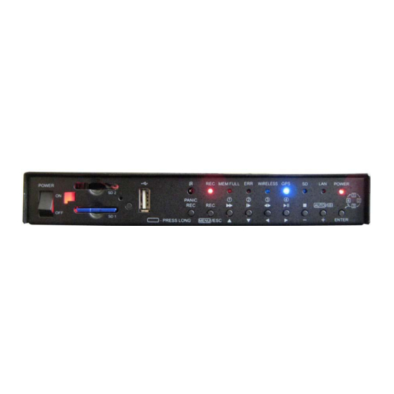
OVERVIEW & CONTROLS Front Panel Power ON/OFF Button 1 USB 2.0 Port Button 2 IR Sensor Button 3 Press this button for Full Frame Recording @1/2 D1 Real-time Button 4 Accesses the Main Menu & go back to the previous menu. Button 5 Fast Forward Button 6... -
Page 10: Rear View
Rear View 1 (CAMERA INPUT) RCA Connectors for Composite Video Signal Input RCA Connectors for connecting the Audio Input. 2 (AUDIO INPUT) 3(AUDIO & VIDEO OUT) RCA Connectors for connecting the Audio & Video Output. 4 (VGA OUTPUT) D-sub 15-pin Connector for connecting the PC Monitor. -
Page 11: Remote Control
Remote Control ○ Button Name Description ○ REMOTE REMOTE CONTROLLER ID in the system CONTROLLER ID setup Iris close and open of PTZ / ○ (IRIS-/+) Frame by Frame(field by field) playback ○ (ZOOM-/+) Zoom in and out of PTZ ○... -
Page 12: Main Screen
MAIN SCREEN A) Front Door B) Rear Door C) Turn Right D) Turn Left E) Braking F) Warning Light G) Emergency H) Shock I) High Speed J) Excessive Braking K) Excessive Speeding L) Lengthy Stop M) Stop w/o W-Light. NOTE: When an event is happening, the icon will glow... -
Page 13: Main Menu
MAIN MENU Before operating the DVR, please make sure that you have properly connected all the cables and HDD’s. Pressing the Menu button on the DVR or from the Remote will open the main menu. Quick Setup Menu Pressing the Quick button will open the Quick Setup page. Select the desired item by pressing ▲, ▼... -
Page 14: Image Size
4.1.2 Image Size Select the desired IMAGE SIZE for recording by pressing the button from the remote. a) 360 X 240 b) 720 X 240 c) 720 X 480 4.1.3 Record Frame Select the desired frame rate for normal recording using the button of the remote. -
Page 15: Screen
SCREEN Select SCREEN Menu by pressing the Enter button from the remote. Select the desired item by pressing ▲,▼ button from the remote controller. 4.2.1 Auto Sequence ▲,▼ Move the cursor to the AUTO SEQUENCE using buttons. ▲,▼ Move the cursor to each single or split channel using the buttons. -
Page 16: Display
4.2.2 Display This menu allows you to select which items will be displayed on the monitoring screen. 4.2.2.1 HDD Free Space button to choose “ON” or “OFF”. Press The default is “ON”. If turned ON the remaining capacity of the fixed (not backup) HDDs will be displayed on the screen. 4.2.2.2 HDD Free Space Mode button to choose “PERCENT”... -
Page 17: Date & Time Mode
4.2.2.5 Date & Time Mode button to choose “YY/MM/DD” or “MM/DD/YY” or “DD/MM/YY”. Use the The default is “YY/MM/DD”. YY/MM/DD : All date and time will be displayed in numbers. Ex. 2005/01/01 00:00:00 MM/DD/YY : the month section will be displayed in character. Ex. -
Page 18: Title
4.2.3 Title ◀,▶ Use the buttons to see the next page. ▲,▼ Press the ENTER button after selecting desired channel using the buttons. ◀,▶ ▲,▼, Select the character using the buttons and then press the ENTER button. To exit this CHARACTER TABLE screen, press the ESC button. CHANNEL TITLE MODE: There are “TEXT”... -
Page 19: Camera
▲,▼ Move the cursor and select the desired item using the buttons. buttons to choose “ON” or “OFF”. Use the ◀,▶ Use the buttons to see the next page. ON: Selected channel will be displayed in black screen (Covert). SELECT: Select among “LIVE&PLAYBACK&NETWORK”, “PLAYBACK&NETWORK”, “LIVE&NETWORK”, “LIVE&PLAYBACK”, “NETWORK”, “PLAYBACK”... -
Page 20: Record
RECORD To set up the RECORD menu, ◀,▶ Move the cursor to the RECORD icon using the in the MENU screen. Press the ENTER button when the cursor is on the RECORD icon and the following items appear. ▲,▼ User can select any item using button from the remote. -
Page 21: Record Program
Move the cursor to choose the desired time using the ▲,▼,◀, ▶ buttons. Select the desired program among PROGRAM 0~9 using the button. Press the ESC button to exit this RECORD SETUP menu or press the ENTER button to enter the RECORD PROGRAM menu. -
Page 22: Audio Record
Select the desired RECORD QUALITY using the button. You will see the size of each image quality and how long you can record with the installed HDDs. To exit this PREVIEW QUALITY menu, press the ESC button. You have to turn the recording “off” to see Image Quality Screen. RECORD TIME: A period how long you can record in free space of installed HDD(s) by setting frame rate. -
Page 23: Holiday
4.3.6 Holiday Set up “ON” or “OFF” of HOLIDAY RECORD using the buttons. ▲,▼ Move the cursor using buttons and set up the value using the buttons . To exit this HOLIDAY menu, press the ESC button. NOTE: DVR will record like SUNDAY recording program on setting HOLIDAY. 4.3.7 Record Limit You can select the Record Limit either “ON”... -
Page 24: Sensitivity
4.4.1.2 Sensitivity ▲,▼ At the MOTION DETECTION menu, move the cursor to SENSITIVITY using buttons. Select the sensitivity level using the buttons. SENSITIVITY: The higher the number, the more sensitive. 1(lowest) ~ 5(highest) 4.4.1.3 Area Setup ▲,▼ At the MOTION DETECTION menu, move the cursor to AREA SETUP using buttons. -
Page 25: Event Indication
4.4.4 Event indication ▲,▼ At the EVENT menu, move the cursor to the EVENT INDICATION using buttons. Select “ON‟ or “OFF” using the buttons to set the event indication. 4.4.5 Sensor Input Select ▲,▼ At the EVENT menu, move the cursor to the SENSOR INPUT SELECT using the buttons. -
Page 26: Gps
◀,▶ Press the button to see the next page. To exit this screen, press the “ESC” button. NOTE - You can set the RELAY OUTPUT of each channel for the event type. - Relay output is from 1 to 4 seconds. You can set the period of the relay output. <RELAY 4 SELECT>... -
Page 27: System
SYSTEM To set up the SYSTEM menu, ▲,▼ Move the cursor to the SYSTEM icon using the in the MENU screen. Press the ENTER button when the cursor is on the SYSTEM icon and the following items appear. 4.5.1 Storage ▲,▼... -
Page 28: Storage Configuration
4.5.1.1 Storage Configuration ▲,▼ At the STORAGE menu, move the cursor to STORAGE CONFIGURATION using the buttons. You can set the SDCARD Memory stick either to Record or Backup Mode. 1) REC: Normal and Event recording. 2) BACKUP: Only for backup. Move the Cursor to EXTERNAL SDCARD to see the below screen. -
Page 29: Clock
If you want to initialize (format) the SD CARD, move the cursor to “YES” and then press the “ENTER” button. If not, move the cursor to “NO” and press the “ENTER” button. To exit this screen, press the ESC button. To exit this HDD menu, press the “ESC”... -
Page 30: Video Standard
▲,▼ At the CLOCK menu, move the cursor to the TIME ADJUST using the buttons. Press the ENTER button when the cursor is on the TIME ADJUST. Select “ON” or “OFF” using the buttons when the cursor is on “INTERNET TIME ADJUST”. If the INTERNET TIME ADJUST is “ON”, the time of DVR will be adjusted to the time offered by an NTP server. -
Page 31: Password Check
To exit this ADVANCED SETUP menu, press the ESC button NOTE: In case that the PASSWORD CHECK is on, only ADMIN can enter the ADVANCED SETUP MENU. 4.5.5.1 Password Check ▲,▼ At the ADVANCED SETUP menu, move the cursor to the PASSWORD CHECK using the buttons. -
Page 32: User Authority
The default of ADMIN is 11111111, USER1 is 22222222, USER2 is 33333333, USER3 is 44444444, USRE4 is 55555555. If you forget the admin password, please contact Speco Technologies. CAUTION: Change the password after purchasing for security reasons. NOTE: You can use only 0~9 number buttons to setup the PASSWORD. -
Page 33: Firmware Upgrade
4.5.6 Firmware Upgrade ▲,▼ At the SYSTEM menu, move the cursor to FIRMWARE UPGRADE using the , buttons. If you want to update firmware using the USB port, move the cursor to “YES” and then press ENTER. If not move the cursor to “NO” and then press the ENTER button. To exit this FIRMWARE UPGRADE screen, press the ESC button. -
Page 34: Dhcp
4.6.1.1 DHCP ▲,▼ At the NETWORK menu, move the cursor to the DHCP using the buttons. Select “OFF” using the button. 4.6.1.2 IP Address ▲,▼ At the NETWORK menu, move the cursor to the IP ADDRESS using the buttons. ◀,▶ Select the desired position using the buttons and set the data value using the buttons. -
Page 35: Dynamic Ip Server
◀,▶ Select the desired position using the buttons and set the data value using the buttons . NOTE: Port setting on DVR and client viewer software must be matched. 4.6.1.7 Dynamic IP Server ▲,▼ At the NETWORK menu, move the cursor to the DHCP using the buttons. -
Page 36: Ptz
▲,▼ Use the buttons to choose the item and use the buttons to set the data value. To exit this RS485 menu, press the ESC button. 4.6.3 ▲,▼ At the SCREEN menu, move the cursor to the PTZ using buttons. Press the ENTER button when the cursor is on the PTZ and the following screen appears. -
Page 37: Send E-Mail
4.6.4.1 Send E-mail ▲,▼ buttons and select “ON” using At the E-MAIL menu, move the cursor to the SEND E-MAIL using the buttons to send e-mails when an event happens. 4.6.4.2 SMTP Server ▲,▼ At the E-MAIL menu, move the cursor to the SMTP SERVER using the buttons to input the e-mail sever address to be used by DVR. -
Page 38: Dvr Location
◀,▶ ▲,▼ Select the character using the buttons and then press the ENTER button. To exit this CHARACTER TABLE screen, press the ESC button. 4.6.6 DVR Location ▲,▼ At the E-MAIL menu, move the cursor to the DVR LOCATION using the buttons . -
Page 39: Wireless
Please note then when using the WIRELESS function, lowering your bandwidth may improve your transmission. To exit, press the ESC button. 4.6.8 Wireless ▲,▼ Move the cursor to WIRELESS screen using the buttons. You can change the WIRELESS mode from “Auto” to “Manual”. If using Auto, WIRELESS will turn on as soon as the DVR is powered up. -
Page 40: Search & Copy
Calendar search provides a quick overview of the year, month, day and hours of the day so that the data can be accessed relatively quickly. Press the SEARCH button to access the search screen. Highlight CALENDAR SEARCH and press the ENTER button to access the CALENDAR SEARCH screen. It will start searching for the data automatically The dates that contain recorded data will be displayed in clear font, whereas dates without data will be in white. -
Page 41: Event Search
Time search provides an overview of the recorded data from the earliest available recording to the latest available recording. 4.7.4 Event Search ▲,▼ Move the cursor to the EVENT SEARCH icon using the in the MENU screen. Press the ENTER button when the cursor is on it and the following screen appears. Event search provides an overview of the all event related recordings so that a specific event can be quickly pinpointed and accessed. -
Page 42: File Search
Block search has the capability to retrieve the recorded data even from hard drives that may have failed during the operation. Block search reads the logical block addressing (LBA) of the hard disk drives where the recorded data are associated chronologically with the actual location of the files. In other words, even if the hard drives are damaged, it may be possible to retrieve data from the hard disk drives. -
Page 43: Log File
4.7.8 Log File The log file keeps a list of the important events that happened to the DVR. The log file can be saved to a USB flash memory as a text file so that it can be viewed and archived to a computer. The following are what the DVR keeps in its log file: ... -
Page 44: Copy Status
Select the desired MEDIA using the buttons. ▲,▼ Move the cursor to HDD ID using the buttons and select the desired HDD to copy among HDD IDs using the buttons . ◀,▶ ▲,▼, Move the cursor to the desired position of COPY START TIME/ COPY END TIME using the buttons. -
Page 45: Media Format
Press the ESC button to exit this menu. 4.8.3 Media Format ▲,▼ At the COPY menu, move the cursor to MEDIA FORMAT using the buttons. Press the ENTER button and the following screen appears. Select the media using the button. Move the cursor to MEDIA FORMAT and then press the “ENTER”... -
Page 46: Dvr Status
4.9.1 DVR Status Move the Cursor to the DVR STATUS icon using ▲,▼ on the remote & press the Enter button to get the below Screen. The status screen displays the basic information about the DVR. Press the STATUS button to access the information screen. -
Page 47: Network Status
4.9.2 Network Status Move the cursor to the Network Status using ▲,▼ button from the remote & then click on it using the Enter button to see the screen below. DHCP (DYNAMIC Displays the status of the DHCP application. IP ADDRESS Displays currently assigned IP address. -
Page 48: Recording Bitrate
4.9.3 Recording Bitrate Move the cursor to the RECORDING STATUS icon and press the ENTER button to see the below Screen. 4.10 EXIT At the MENU screen, Move the cursor to the EXIT icon using the ◀,▶ buttons. Press the ENTER button when the cursor is on the EXIT icon and the following items appear. ▲,▼... -
Page 49: Wireless
WIRELESS INTRODUCTION With an Air Card, the mobile DVR can connect the network wirelessly. The information of DVR status, location, live image, recording image will transmitted to Software (Media viewer or Mobile Manager). INSTALLATION Install the DVR without ETHERNET connection. Media Viewer Install the program on a PC. -
Page 50: Operation
Insert the Air Card into front of DVR. Air card must be USB type. Operation Press the button for about two seconds. 7.3.1 DVR Menu Setting Enter the Menu, select the LINK. Select the WIRELESS. 7.3.1.1 Auto/Manual Select the WIRELESS MODE between AUTO and MANUAL. * AUTO: When the DVR is POWER ON, wireless connection will work automatically. -
Page 51: Verification
Verification 7.4.1 DVR Status Enter DVR STATUS, select the NETWORK STATUS. The IP ADDRESS will be changed if wireless connection is success. 7.4.2 DVR Screen The Monitor screen will display “Connected” and the Wireless LED of the DVR will be on if the wireless connection is a success. -
Page 52: Verification
Verification The DVR is connected. MOBILE MANAGER Connection Execute the Mobile Manager on PC. If MOBILE SERVER SETTING is correct, the list of mobile DVR‟s will display on Mobile Manger automatically. -
Page 53: Mobile Server Setting
Select the list of mobile DVR (image A), and press „Connect‟ button (image B). The DVR is connected. The location on the MAP and LIVE image and DVR information will display. 9.1.1 Mobile Server Setting Enter the MENU, select the LINK and WIRELESS. Insert the SERVER IP address. -
Page 54: Verification
If the PC uses firewall or common router, this PC can‟t be DVR SERVER. If it is behind a router, make the PC port to “12313”. Verification The DVR is now connected.
Need help?
Do you have a question about the DVRM42 and is the answer not in the manual?
Questions and answers