Advertisement
Quick Links
Authorised Distributors:-
Intech Systems Chennai Pvt. Ltd, Chennai-600 032
Ph: 4353 8888 Mob: 99 4353 8888 Fax: 044 4353 7888
E-mail: info@intechchennai.com Website: www.intechchennai.com
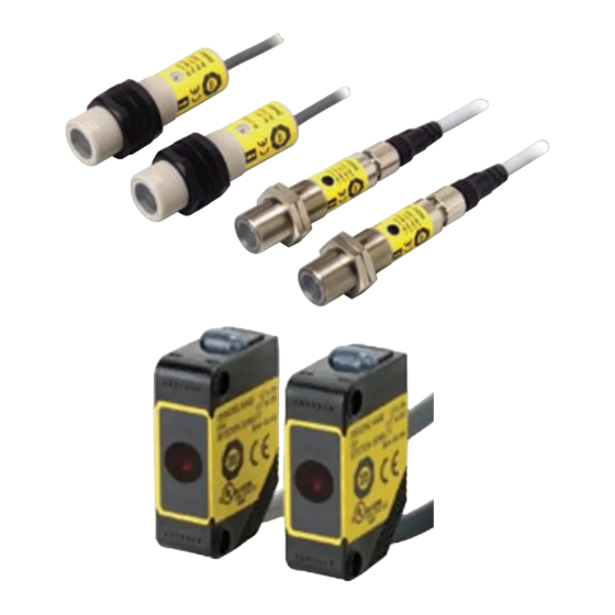
Single-beam Safety Sensor
E3ZS/E3FS
Detects Intrusions into Hazardous
Areas with a Single Beam and
Complies with International Safety
Standards.
Be sure to read the "Safety Precautions" on page 15
and the "Precautions for All Safety Sensors"
Features
Connect up to 4 sets of E3ZS/E3FS per
Connect to a B1 Module for F3SX to Create a Type 2 Safety Sensor
Note: The B1 Module is designed specifically for E3ZS/E3FS input of t
error occurs with one or more of the E3ZS/E3FS Sensors connected to the B1 Module.
E 3ZS
E 3F S
Connect s s imply and ea s ily u s in g a wide ran ge of acce ss orie s .
For unus ed E 3ZS /E 3F S S ens or connector s
With Right- angle Connector s
.
B1 Module for F3SX
he F3SX. The safety output turns OFF when light is interrupted o
E 3F S
Dummy plug
F 3S X-EB1 s hown
E 3F S -10B4-M1-M
E3FS
Safety Controller
E 3F S -10B4 2M
With Right- angle Connector s
CSM_E3ZS_E3FS_DS_E_2_1
E3ZS
r when an
B1 Mod ule for the F 3S X
(F 3S X-EB1 s hown here)
E 3ZS -T81A
1
Advertisement

Subscribe to Our Youtube Channel
Related Manuals for Omron E3ZS


Summary of Contents for Omron E3ZS
- Page 1 F3SX. The safety output turns OFF when light is interrupted o r when an error occurs with one or more of the E3ZS/E3FS Sensors connected to the B1 Module. B1 Mod ule for the F 3S X (F 3S X-EB1 s hown here)
- Page 2 Note: Test Input Use this function to enable the emitter of E3ZS to be turned ON/OFF from outside. It is possible to detect a number of E3ZS errors by monitoring the status of the test input and the E3ZS output signal.
- Page 3 Brass E3FS-10B4-M1-M 10 m connector Controller Instant Breaking Models F3SX-N-@@@R (with Relay Safety Output) Input types Model Width (W) Weight E3ZS/E3FS Safety F3SJ/F3SN/F3SH Emergency Stop Door Switches Sensors Safety Light Curtains Switches 4 sets 1 set F3SX-N-B1R 90.0 mm Approx. 0.5 kg...
- Page 4 The F3SX-series Safety Controller is a multiple input, single output Controller. This is useful for individual control over the safety output when using multiple safety input devices. Custom models are also available. Refer to the F3SX, and consult with your OMRON representative.
- Page 5 Overall cable length for both an E3FS Receiver connected to an F3SX and the Emitter connected to the F3SX must be within 50 m. • Overall cable length for both an E3ZS Receiver connected to an F3SX and the Emitter connected to the F3SX must be within 100 m. Cables with Connector (Socket) on One End...
- Page 6 E3ZS/E3FS Accessory Connection Example Emitter Receiver (E3FS-10B4-M1-M) Branch Connector for the E3FS Cable with Connectors on Both Ends Cable with Connectors on Both Ends (F39-CN3) (XS2W-D42@-@81-@) (XS2W-D42@-@81-@) Single-beam Safety Sensor First Sensor Connector Cable with Connectors on Both Ends for Single-beam Safety Sensor Branch...
- Page 7 Diameter 6.7 mm / diameter 9 mm Sensing distance 0.2 to 3 m 0 to 10 m Response time (under stable light incident 1.0 ms (E3ZS only) *1 2.0 ms (E3FS only) *1 condition) Startup waiting time 100 ms Power supply voltage (Vs) 12 to 24 VDC±10% (ripple p-p 10% max.) *2...
- Page 8 E3ZS/E3FS Connections Circuit Diagram Example F3SX-EB1 (Manual Reset) Single-beam Safety Sensor 1 E3ZS-T81A/E3FS-10B4@@@ Emitter Receiver Circuit diagram example without an E3FS-10B4@@@ Single-beam Safety Sensor installed. Single-beam Safety Sensor 2 E3ZS-T81A/E3FS-10B4@@@ Emitter Receiver 24 VDC Fuses T11 T12 T21 T22 Control circuits...
- Page 9 *2. Make sure to connect the pink wire (mode selection input 2) to 24 VDC. *3. Make sure to connect to the 0V terminal when the E3ZS is not connected to an F3SX and the test input is not used.
- Page 10 E3ZS/E3FS Engineering Data E3ZS Parallel Operating Range Mutual Interference Range Excess Gain Ratio Emitter Emitter Receiver Receiver −50 −50 −100 −100 −150 −150 −200 −200 Distance X (m) Distance (m) Distance X (m) E3FS Parallel Operating Range Mutual Interference Range...
- Page 11 E3ZS/E3FS Dimensions (Unit: mm) Sensors Pre-wired Cable with ABS Resin Case 10.8 10.4 3.54 E3ZS-T81A Operation indicator (Receiver only) Emitting indicator (Emitter only) Stability indicator (Receiver only) 6.7 dia. Lens Beam 25.4 15.5 2-M3 Vinyl-insulated round cord with four Receiver conductors and three Emitter conductors, 4 dia.
- Page 12 Dummy Plug Sensor Mounting Bracket (for E3FS) F39-CN4 Y92E-B18 32±0.2 17 max. 47 max. Material: Plastic 18 dia. Hexagonal bolt: M5 x 32 Sensor Mounting Bracket (for E3ZS) R1.7 R1.7 3.4 E39-L104 14° 12.5 (13.7) R3.5 R25.4 (39) 37.8 Material: Stainless steel (SUS304) R1.6...
- Page 13 E3ZS/E3FS Cables with Connectors on Both Ends for Branch Connection F39-JF1S F39-JF2S F39-JF5S 30±10 F39-JF10S 14.9 dia. Model L (mm) 40.7 +150 F39-JF1S 1,000 Vinyl-insulated round cord, 6 dia. (gray), * Dimensions will vary with the model as shown in the table on the left.
- Page 14 E3ZS/E3FS Cables with Connector (Socket) on One End XS2F-D421-C80-A (L=1m) 6 dia. XS2F-D421-D80-A (L=2m) XS2F-D421-G80-A (L=5m) 14.9 dia. XS2F-D421-J80-A (L=10m) XS2F-D421-C80-R (L=1m) 40.7 XS2F-D421-D80-R (L=2m) 45° 45° XS2F-D421-G80-R (L=5m) 5 dia. 5 dia. XS2F-D421-J80-R (L=10m) XS2F-D422-C80-A (L=1m) 25.3 XS2F-D422-D80-A (L=2m) 6 dia.
- Page 15 E3ZS-T81A/E3FS-10B4 Leave ade quate space between the Sensors during installation. 2). Normal operation may not be possi ble if another (Refer to the instruction manuals for the E3ZS/E3FS and the Single- beam Sensor Controller is used. F3SN/F3SH.) The Sensor cannot be used as part of a safety system Use baffle plates to separate Sensors.
Need help?
Do you have a question about the E3ZS and is the answer not in the manual?
Questions and answers