Table of Contents
Advertisement
Quick Links
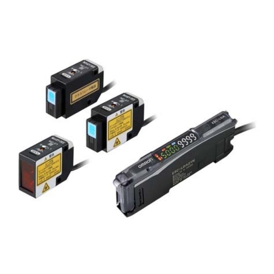
Photoelectric Sensor with Separate Digital Amplifier (Laser-type)
E3C-LDA@N
Variable Laser Beam for Spot, Line, or
Area Detection
• Long-distance detection (diffuse reflective: 1 m,
retro-reflective: 7 m).
• Beam shape selectable from spot, line, and
area types to match various applications.
• Adjustable spot diameter.
• Adjustable optical axis.
Refer to Safety Precautions on page 8.
Features
■ Provide ample long-distance detection of 1,000 mm.
Diffuse Reflective
Model
Three beam types means a wider variety of applications.
■Spot, Line, and Area Types
Suitable for various applications.
Mount Beam Units to a Spot Type Sensor to
convert to Line or Area Type.
Spot Type
E3C-LD11N
Line Type
E3C-LD11N
+ E39-P11
Area Type
E3C-LD11N
+ E39-P21
■ Easy Sensor Installation and Sensing Characteristics
Coaxial Retroreflective
Model
Equivalent to Through-beam Sensors.
Optical axis alignment range:
Approximately r1 to1.5q
At 1 m: Minimum spot diameter of 0.8 mm
E39-R13
■Optical Axis Adjustment Mechanism
The sensor detection point can be easily changed.
8 mm - 0.2 mm - 3.5 mm
(VR minimum) (VR median) (VR maximum)
■Variable Focal Point Mechanism
■Spot, Line, and Area Types
■Coaxial Optical System
The coaxial optical system and laser beam allow high-precision detection.
The built-in MSR Function inhibits the effect of reflected light from the workpiece.
For the most recent information on models that have been certified for
safety standards, refer to your OMRON website.
At 1,000 mm: Minimum spot diameter of 950 µm
Optical axis alignment range:
Approximately ±2°
At distance of 150 mm
7 mm - 28.5 mm - 33 mm
(VR minimum) (VR median) (VR maximum)
5 to 15 mm
(VR minimum) (VR maximum)
At distance of 150 mm
5 to 33 mm
(VR minimum)(VR maximum)
■Optical Axis Adjustment Mechanism
Sensing
distance of
1 m.
■Variable Focal Point Mechanism
Spot diameter can be adjusted to
enable ultra-high-precision
positioning.
Sensing
distance of
7 m.
Spot Type
E3C-LR11N
1
Advertisement
Table of Contents

Related Manuals for Omron E3C-LDA-N Series


Summary of Contents for Omron E3C-LDA-N Series
- Page 1 • Adjustable optical axis. Refer to Safety Precautions on page 8. For the most recent information on models that have been certified for safety standards, refer to your OMRON website. Features ■ Provide ample long-distance detection of 1,000 mm. Diffuse Reflective...
-
Page 2: Ordering Information
Model length conductors PFP-M Master E3X-CN21 Connector Note: Refer to PFP-@N/-M/-S on your OMRON website for details. Reflectors (Required when using retro-reflective models) Slave E3X-CN22 A Reflector is not provided with the Sensor head. Be sure to Connector order a Reflector separately. -
Page 3: Ratings And Specifications
E3C-LDA@N Ratings and Specifications Sensor Heads Type Diffuse-reflective Coaxial Retro-reflective (with MSR function) E3C-LD11N + E3C-LD11N + E3C-LR11N + E3C-LR11N + Item Model E3C-LD11N E3C-LR11N E3C-LR12N E39-P11 E39-P21 E39-P31 E39-P41 1 mW max. Red semiconductor laser diode (650 nm), Red semiconductor laser diode (650 nm), (JIS Class 1, Light source 3 mW max. - Page 4 E3C-LDA@N Amplifier Units NPN output E3C-LDA21N E3C-LDA6N E3C-LDA7N Model PNP output E3C-LDA51N E3C-LDA8N E3C-LDA9N Connection method Pre-wired Wire-saving Connector Applicable Amplifier Unit E3C-L@@@N Outputs 2 outputs 2 outputs 1 output External input 1 input 1 input Supply voltage 12 to 24 VDC ±10%, ripple (p-p) 10% max. Power consumption Power consumption: 1080 mW max.
-
Page 5: Engineering Data (Reference Value)
E3C-LDA@N Engineering Data (Reference Value) Minimum Beam Diameter vs. Sensing Distance E3C-LD11N E3C-LR11N E3C-LR12N 1000 Y direction X direction Y direction X direction 700 800 1000 Distance (mm) Distance (m) Distance (m) Beam Shape vs. Sensing Distance E3C-LD11N + E39-P11 E3C-LD11N + E39-P21 X direction X direction... -
Page 6: I/O Circuit Diagrams
E3C-LDA@N I/O Circuit Diagrams NPN Output Operation Model Timing chart L/D indicator Output circuit mode ch1/ Incident light No incident light OUT indicator (orange) Not lit Light-ON Output OUT2 indicator lit. Display transistor (orange) Brown Operate Load Load (e.g., relay) Reset Black (Between brown and... - Page 7 E3C-LDA@N PNP Output Operation Model Timing chart L/D indicator Output circuit mode ch1/ Incident light No incident light OUT indicator (orange) Not lit Light-ON Output lit. OUT2 indicator (orange) Display transistor Brown Load Operate External (e.g., relay) Reset OUT1 Pink input (Between blue and indicator...
-
Page 8: Safety Precautions
[OUT1 Selection Indicator/OUT2 Selection Indicator] The indicator for the selected output channel is lit. Used to fine-tune the threshold. Safety Precautions Be sure to read the precautions for all models in the website at: http://www.ia.omron.com/. Warning Indications Meaning of Product Safety Symbols Warning level... -
Page 9: Precautions For Safe Use
E3C-LDA@N Sensor Heads Precautions for Correct Use Please observe the following precautions to prevent failure to WARNING operate, malfunctions, or undesirable effects on product performance. This product is not designed or rated for ensuring 1. Do not install the product in locations subjected to the following safety of persons either directly or indirectly. - Page 10 • Confirm that the operation lever has reset and that the cladding is in the insertion opening. (Pull lightly on the line. If you feel resistance, then the connection is okay.) Refer to XN2 on your OMRON website for details of connecting the connector.
-
Page 11: Laser Safety
• When exporting to Europe, labels fall under EU standard The E3C-LD11N/E3C-LR@@N are classified as a class-II laser by the EN60825-1. FDA, and it has already been registered with the CDRH (Center for Devices and Radiological Health). Ask your OMRON representative for details. - Page 12 E3C-LDA@N Amplifier Units Precautions for Correct Use 1. Do not miswire such as the polarity of the power supply. WARNING 2. Be sure to mount the unit to the DIN track until it clicks. 3. When using a connector type product, place a protective label This product is not designed or rated for ensuring (provided with the E3X-CN series) on the power supply connecting safety of persons either directly or indirectly.
- Page 13 E3C-LDA@N Mounting Mounting, Removing and Joining Amplifier Units (Mounting on DIN Track) Mounting and removing the sensor head 1. Let the hook on the Amplifier Unit's Sensor Head connection side 1. Open the protective cover. catch the track. 2. With the locking lever on the sensor head connector facing up, 2.
- Page 14 E3C-LDA@N (Unit: mm) Dimensions Tolerance class IT16 applies to dimensions in this data sheet unless otherwise specified. Sensor Heads E3C-LD11N 12.7 LD ON indicator 18.5 Mounting Holes Operation indicator ±0.1 13.2 13.2 12.8 18.8 ±0.1 2.7 dia. Two, M3 Optical axis alignment screw Two, 3.2 dia holes 4.75 27.7...
- Page 15 E3C-LDA@N E3C-LR11N E3C-LR12N 24.5 LD ON indicator Mounting Holes 18.7 Operation indicator ±0.1 13.2 13.2 12.8 18.8 ±0.1 2.7 dia. Two, M3 Optical axis alignment screw 33.8 Two, 3.2 dia holes Emitter Optical axis center FOCUS Adjustment Screw R4.8 (E3C-LR11N only) 3 dia.
- Page 16 E3C-LDA@N Amplifier Units Pre-wired Amplifier Units E3C-LDA21N E3C-LDA51N Side B 30.2 27.8 * The Mounting Bracket can also be used on side B. 0.25 32.1 36.7 57.7 83.4 83.4 Mounted to DIN Track 167.8 167.8 (max. value with Protective cover open) (max.
- Page 17 E3C-LDA@N Amplifier Units with Wire-saving Connectors E3C-LDA6N E3C-LDA7N E3C-LDA6N/LDA8N E3C-LDA7N/LDA9N E3C-LDA8N Side B *1 *1 The Mounting Bracket E3C-LDA9N 30.2 27.8 30.9 27.1 can also be used on side B. 0.25 32.1 36.7 57.7 83.4 83.4 13 *3 Mounted to DIN Track 167.8 167.8 (max.
-
Page 18: Accessories (Sold Separately)
E3C-LDA@N Accessories (Sold Separately) Wire-saving Connectors Master Connector E3X-CN21 2,000 Edge of Amplifier Unit Cable * Cable: 4-dia. cable with 4 conductors, Standard cable length: 2 m (Conductor cross-section: 0.2 mm (AWG24), Insulator diameter: 1.1 mm) Slave Connector E3X-CN22 2,000 Edge of Amplifier Unit Cable * Cable: 4-dia. -
Page 19: Terms And Conditions Agreement
Return of any Products by Buyer must be approved in writing by Omron before shipment. Omron Companies shall not be liable for the suitability or unsuitability or the results from the use of Products in combination with any electrical or electronic components, circuits, system assemblies or any other materials or substances or environments. - Page 20 The Netherlands Hoffman Estates, IL 60169 U.S.A. Tel: (1) 847-843-7900/Fax: (1) 847-843-7787 Tel: (31)2356-81-300/Fax: (31)2356-81-388 © OMRON Corporation 2022 All Rights Reserved. OMRON (CHINA) CO., LTD. OMRON ASIA PACIFIC PTE. LTD. In the interest of product improvement, Room 2211, Bank of China Tower, No.
Need help?
Do you have a question about the E3C-LDA-N Series and is the answer not in the manual?
Questions and answers