Table of Contents
Advertisement
Quick Links
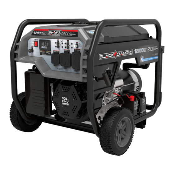
OPERATOR'S MANUAL
MODEL #BD201306
9500W ELEcTRic START GENERATOR
SERIAL NO.
Register your product at:
championpowerequipment.com
1-888-376-7375
or visit black-diamond.com
SAVE THESE iNSTRUcTiONS. This manual contains important safety precautions which should be read and understood before operating the product. Failure to do
so could result in serious injury. This manual should remain with the product.
Specifications, descriptions and illustrations in this manual are as accurate as known at the time of publication, but are subject to change without notice.
This product meets the requirements of the PGMA (Portable Generator Manufacturers' Association) standard ANSI/PGMA G300-2018 (Safety and Performance of
Portable Generators).
Covered by one or more of the following U.S. Patent Numbers: 10,862,414 and other U.S. and foreign patents pending.
EN
4605-M-OP REV 20240320
Mid-States Distributing, LLC., 2800 Meacham Blvd., Fort Worth, TX 76137 USA
Advertisement
Table of Contents

Related Manuals for Black Diamond Equipment BD201306


Summary of Contents for Black Diamond Equipment BD201306
- Page 1 OPERATOR’S MANUAL MODEL #BD201306 9500W ELEcTRic START GENERATOR SERIAL NO. Register your product at: championpowerequipment.com 1-888-376-7375 or visit black-diamond.com SAVE THESE iNSTRUcTiONS. This manual contains important safety precautions which should be read and understood before operating the product. Failure to do so could result in serious injury.
- Page 2 CARBON MONOXIDE SAFETY: THE BIG PICTURE As the only safe way to use a portable generator, taking your generator outside is absolutely mandatory to keep your family safe from carbon monoxide. But there’s even more you can do. By educating yourself about all carbon monoxide risks, you’ll be better prepared to protect CARBON MONOXIDE K ILLS your family from this colorless, oderless threat.
-
Page 3: Table Of Contents
TABLE Of cONTENTS introduction Maintenance ....................Cleaning the Generator .......... Safety Definitions .......... Changing the Engine Oil ......... -
Page 4: Introduction
(e.g., messages relating to property damage). model and serial numbers of your product. Transcribe the information found on your product’s dataplate label to the table below BLACK DIAMOND TECHNICAL SUPPORT TEAM 1-888-376-7375 MODEL NUMBER BD201306 SERIAL NUMBER DATE OF PURCHASE PURCHASE LOCATION... -
Page 5: Important Safety Instructions
iMPORTANT SAfETY iNSTRUcTiONS WARNiNG DANGER Cancer and Reproductive Harm – www.P65Warnings.ca.gov Operate equipment with guards in place. Rotating parts can entangle hands, feet, hair, clothing and/or accessories. Traumatic amputation or severe laceration can DANGER result. Generator exhaust contains carbon monoxide, a colorless, Keep hands and feet away from rotating parts. - Page 6 iMPORTANT SAfETY iNSTRUcTiONS WARNiNG cAUTiON Spark from removed spark plug wire can result in fire or Start the generator and allow the engine to stabilize before electrical shock. connecting electrical loads. Connect electrical equipment in the off position, and then turn When servicing the generator: them on for operation.
-
Page 7: Fuel Safety
iMPORTANT SAfETY iNSTRUcTiONS fuel Safety WARNiNG DANGER When starting the generator: Do not attempt to start a damaged generator. GASOLINE AND GASOLINE VAPORS ARE HIGHLY FLAMMABLE AND EXPLOSIVE. Always check that the gasoline cap, air filter, spark plug, fuel lines and exhaust system are properly in place. -
Page 8: Safety And Dataplate Labels
PHASE WATTS D'ESSENCE D: Change size to 260 x 36 MODEL BD201306 POWER FACTOR MODÈLE This artwork belongs to Champion Power Equipment. The contents are confidential and privileged and shall not be disclosed to or used by or for FACTEUR DE outside parties without the explicit consent of Champion Power Equipment. -
Page 9: Safety Symbols
iMPORTANT SAfETY iNSTRUcTiONS Safety Symbols Some of the following symbols may be used on this product. Please study them and learn their meaning. Proper interpretation of these symbols will allow you to more safely operate the product. SYMBOL MEANING Read Operator’s Manual. To reduce the risk of injury, user must read and understand operator’s manual before using this product. -
Page 10: Operation Symbols
iMPORTANT SAfETY iNSTRUcTiONS Operation Symbols Some of the following symbols may be used on this product. Please study them and learn their meaning. Proper interpretation of these symbols will allow you to more safely operate the product. SYMBOL MEANING SYMBOL MEANING Choke Run time... -
Page 11: Quick Start Label Symbols
iMPORTANT SAfETY iNSTRUcTiONS Quick Start Label Symbols Some of the following symbols may be used on this product. Please study them and learn their meaning. Proper interpretation of these symbols will allow you to more safely operate the product. 5W-30 4601-L-OP-A Starting the Engine - Manual Start Stopping the Engine... -
Page 12: Controls And Features
cONTROLS AND fEATURES Read this operator’s manual before operating your generator. Familiarize yourself with the location and function of the controls and features. Save this manual for future reference. Generator 1. Gasoline Tank – 8.5 gal. (32 L) 8. Ground Terminal – Consult an electrician for local grounding regulations. -
Page 13: Control Panel
cONTROLS AND fEATURES control Panel 1. Choke Knob – Used to start a cold engine. RECEPTACLES 2. Ignition Switch – Used to START or STOP the generator. 120/240V AC, 30A Locking (NEMA L14-30R) 3. Intelligauge – See Intelligauge section. May be used to supply electrical power for operation of 120/240 Volt AC, 30 Amp, single 4. -
Page 14: Intelligauge With Co Shield
cONTROLS AND fEATURES intelligauge with cO Shield ® Four mode digital meter for displaying voltage, frequency, session run time, and total run time. A. CO Shield LED – The CO Shield technology monitors ® ® for accumulation of poisonous carbon monoxide (CO) gas produced by engine exhaust when the generator is running. -
Page 15: Industry Canada: Can Ices-002/Nmb-002
cONTROLS AND fEATURES industry canada: cAN icES-002/NMB-002 Assembly Parts Wheels * Applicable in Canada only. 9.5 in. (24.1 cm) Never Flat Wheel (A) ......This device complies with Industry Canada license - exempt RSS standard(s). Roll Pin (B) ............Large R-clip (C) .......... -
Page 16: Assembly
ASSEMBLY Install the Support Leg Your generator requires some assembly. This unit ships from our factory without oil. It must be properly serviced with fuel and oil 1. Attach the support leg (D) to the generator frame with flange before operation. bolts (E) . -
Page 17: Add Engine Oil
ASSEMBLY Add Engine Oil 4. Check engine oil level at every use and add as needed. WARNiNG DO NOT attempt to crank or start the engine before it has been properly filled with the recommended type and amount of oil. OIL DIP STICK Damage to the generator as a result of failing to follow these instructions will void your warranty. -
Page 18: Add Fuel
ASSEMBLY Add fuel 4. Screw on the gasoline cap and wipe away any spilled fuel. cAUTiON DANGER Use unleaded gasoline with a minimum octane rating of 87 Gasoline vapors are highly flammable and extremely explosive. and an ethanol content of 10% or less by volume. DO NOT light or smoke cigarettes. -
Page 19: Grounding
ASSEMBLY Grounding Your generator must be properly connected to an appropriate ground to help prevent electric shock. WARNiNG Failure to properly ground the generator can result in electric shock. A ground terminal connected to the frame of the generator has been provided (see Controls and Features for terminal location). -
Page 20: Operation
OPERATiON cO Shield - carbon Monoxide (cO) Detection ® Move the generator far away to an open, outdoor area and point the exhaust away from people and buildings. Once relocated and Auto-shutoff System to a safe area, the generator can be restarted, and the proper CO Shield technology monitors the accumulation of carbon ®... -
Page 21: Generator Location
OPERATiON Generator Location WARNiNG WARNiNG Do not expose to rain or use in damp locations. Keep all objects a minimum of 5 feet (1.5m) away from the NEVER operate the generator inside any building, garage, generator at all times. Heat from the muffler surface and basement, crawlspace, shed, enclosure or compartment, exhaust gas stream can ignite combustible materials. - Page 22 OPERATiON Electric Start Manual Start 2. Pull choke knob out to the full “CHOKE” position. 2. Push the ignition switch to the “ON” position. 2a. For restarting a warm engine, pull the choke knob out to 75% of the full “CHOKE” position. 3.
-
Page 23: Battery
OPERATiON connecting Electrical Loads NOTicE Let the engine stabilize and warm up for a few minutes after Keep choke knob in “CHOKE” position for only 1 pull of the starting. recoil cord. After first pull, press the choke knob in to the Plug in and turn on the desired 120 or 240 (if applicable) Volt AC “RUN”... -
Page 24: Do Not Overload Generator
OPERATiON Do Not Overload Generator To ensure proper operation of the GFCI duplex, perform this test monthly: Capacity 1. With the generator running, plug a lamp into the GFCI Follow these simple steps to calculate the running and starting receptacle. Turn the lamp on. watts necessary for your purposes: 2. -
Page 25: Stopping The Engine
OPERATiON Stopping the Engine WARNiNG 1. Turn off and unplug all connected electrical loads. Never start The folding handle is not long enough to hold and walk with a or stop the generator with electrical devices plugged in or full stride when moving the generator. - Page 26 OPERATiON Carb. Code High Alt. Jet Part Number Min. Altitude 3000-6000 ft. 16161-000054 (914-1829 m) 16100- 000006 6000-8000 ft. 16161-000009 (1829-2438 m) WARNiNG Operation using the alternative main jet at elevations lower than the recommended minimum altitude can damage the engine.
-
Page 27: Maintenance
MAiNTENANcE changing the Engine Oil Make certain that the generator is kept clean and stored properly. Only operate the unit on a flat, level surface in a clean, dry Change oil when the engine is warm. Refer to the oil specification operating environment. -
Page 28: Cleaning And Adjusting The Spark Plug
MAiNTENANcE cleaning and Adjusting the Spark Plug 5. Squeeze in a clean, absorbent cloth to remove all excess oil. 6. Place the filter in the assembly. 1. Remove the spark plug cable from the spark plug. 7. Reattach the air filter cover and snap in place. 2. -
Page 29: Adjusting The Governor
MAiNTENANcE Adjusting the Governor Maintenance Schedule Follow the service intervals indicated in the following maintenance WARNiNG schedule. Tampering with the factory set governor will void your Service your generator more frequently when operating in adverse warranty. conditions. Contact our Technical Support Team at 1-888-376-7375 to locate The air-fuel mixture is not adjustable. -
Page 30: Storage
STORAGE 5d. When gasoline stops flowing from the carburetor, replace WARNiNG and tighten the carburetor drain bolt and be sure to properly dispose of the drained gasoline according to To avoid accidental or unintended ignition of your generator local regulations or guidelines. during periods of storage, the following precautions should be followed: 6. -
Page 31: Removing From Storage
STORAGE Removing from Storage NOTicE If the generator has been improperly stored for a period longer than 30 days with ethanol blended gasoline in the gasoline tank and/or carburetor, all fuel must be drained and the carburetor must be thoroughly cleaned of ethanol build up. -
Page 32: Specifications
Generator Model ........BD201306 Use unleaded gasoline with a minimum octane rating of 87 and an ethanol content of 10% or less by volume. DO NOT USE E15 or Start Type . -
Page 33: Troubleshooting
TROUBLESHOOTiNG Problem Cause Solution No fuel. Add fuel. Faulty spark plug. Clean and adjust spark plug or replace. Fill crankcase to the proper level. Low oil level. Place generator on a flat, level surface. Spark plug wire loose. Attach wire to spark plug. Engine will not start. - Page 34 TROUBLESHOOTiNG Problem Cause Solution Move generator to an open, outdoor area. Point exhaust away from people and buildings. Move to fresh air and get medical help if sick, dizzy, or weak. Make sure there are no objects creating obstructions within 5 feet of the generator. Obstructions in the vicinity of the generator may trap carbon monoxide emissions near the If equipped, when CO Shield...
- Page 35 TROUBLESHOOTiNG Problem Cause Solution Review load and adjust. See “Connecting Overload. Electrical Loads.” Repeated circuit breaker tripping. Check for damaged, bare or frayed wires. Replace Faulty power cords or device. defective device. Circuit breaker still too hot. Let unit sit for 5 mins. For other issues and technical support: Technical Support Team Toll Free 1-888-376-7375...
-
Page 36: Warranty
WARRANTY Other Exclusions CHAMPION POWER EQUIPMENT 3 YEAR LIMITED WARRANTY This warranty excludes: – Cosmetic defects such as paint, decals, etc. Warranty Qualifications – Wear items such as filter elements, o-rings, etc. To register your product for warranty please visit: –... - Page 37 CHAMPION POWER EQUIPMENT, INC. (CPE) AND THE UNITED STATES ENVIRONMENTAL PROTECTION AGENCY (U.S. EPA) EMISSION CONTROL SYSTEM WARRANTY Your Champion Power Equipment (CPE) engine complies with U.S. EPA emissions regulations. YOUR WARRANTY RIGHTS AND OBLIGATIONS: The US EPA and CPE are pleased to explain the Federal Emission Control Systems Warranty on your 2024 small off-road engine (SORE) and engine powered equipment.
- Page 38 EMISSION CONTROL SYSTEM WARRANTY The following are specific provisions relative to your Emission Control System (ECS) Warranty Coverage. 1. APPLICABILITY: This warranty shall apply to 1997 and later model year small off-road engines (SORE). The ECS Warranty Period shall begin on the date the new engine or equipment is delivered to its original, end-use purchaser, and shall continue for 24 consecutive months thereafter.
- Page 39 EMISSION-RELATED PARTS INCLUDE THE FOLLOWING: (using those portions of the list applicable to the engine) Systems covered by this Parts Description warranty Fuel Metering System Fuel regulator, Carburetor and internal parts Air Induction System Air cleaner, Intake manifold Ignition System Spark plug and parts, Magneto ignition system Exhaust System Exhaust manifold, catalytic converter...
Need help?
Do you have a question about the BD201306 and is the answer not in the manual?
Questions and answers