Panasonic FX-501 Series Instructions Manual
Digital fiber sensor amplifier
Hide thumbs
Also See for FX-501 Series:
- Instruction manual (9 pages) ,
- Instruction manual (4 pages) ,
- Instruction manual (4 pages)
Advertisement
Digital Fiber Sensor Amplifier
FX-501□, FX-502□, FX-505□-C2 Series
Thank you for purchasing products from Panasonic Electric Works SUNX
Co., Ltd. Please read this Instruction Manual carefully and thoroughly for
the correct and optimum use of this product. Kindly keep this manual in a
convenient place for quick reference.
● Never use this product as a sensing device for personnel protection.
● In case of using sensing devices for personnel protection, use prod‑
ucts which meet laws and standards, such as OSHA, ANSI or IEC
etc., for personnel protection applicable in each region or country.
Compliance with standards
1
This product complies with the following standards and
regulations.
● For the EU: EMC Directive 2004/108/EC
● For the US and Canada:
ANSI/UL60947‑5‑2, CAN/CSA C22.2 No.14
● For Korea: S1‑G‑1‑2009, S2‑W‑5‑2009
*
In case you require a UL listing mark or C-UL
listing mark, use a class 2 power supply unit.
2
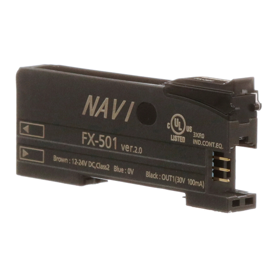
Part description
FX-501□
1
2
9
1
Operation indicator for sensing output (orange)
2
Digital display (green/red)
3
UP key (+)
Functions:
● Teach
4
DOWN key (–)
● Fine adjustment of the threshold value
● Select settings
5
MODE key
Functions:
● Select modes
● Cancel
6
SET key
Functions:
● Teach
● Save selected settings
7
Mode indicator PRO mode (yellow), see page 6
8
Mode indicator CUST (custom) mode (yellow), see page 5
9
Mode indicator L /D (Light‑ON/Dark‑ON) mode (yellow)
FX-502□ and FX-505□-C2
1 2
3
0
1,
Sensing output 1 (lit if output is active)
● Orange: Sensing output is operating
2
Sensing output 2 (lit if output is active)
● Orange: Sensing output is operating
3
Digital display (green/red)
InstructIons
WARNING
3
4
8
7
6
5
4
5
9
8
7
6
4
UP key (+)
Functions:
5
DOWN key (–)
6
MODE key
Functions:
7
SET key
Functions:
8
Mode indicator PRO mode (yellow)
9
Mode indicator CUST (custom) mode (yellow)
0
Mode indicator L /D (Light‑ON/Dark‑ON) mode (yellow)
*
To toggle the key lock function ON/OFF, press the SET and the
MODE key together for 3 seconds.
3
Mounting
Installation to a DIN rail
1. Attach the railing on the rear of the ampli‑
fier to the DIN rail.
2. Push the amplifier in the direction of the
arrow as illustrated so that it attaches
securely.
Removal from a DIN rail
1. Push the amplifier forward.
2. Lift the front part of the amplifier up.
Connecting the fiber cable
*
The attachments to the fiber cables need to be fitted BEFORE
you insert the fibers into the amplifier. For details, refer to the
instruction manual enclosed with the fibers.
1. Snap the fiber lock lever 1 down as
far as it will go.
2. Insert the fiber cables slowly into the
inlets until they stop (see note).
3. Return the fiber lock lever to the
original position.
*
With the coaxial reflective type fiber, such as FD-G4 or FD-FM2,
insert the single core fiber cable into the inlet for the emitter 2
(inlet on the amplifier is labeled "P") and the multi-core fiber
cable into the inlet for the receiver 3. If they are inserted the
wrong way round, the sensing performance will deteriorate.
1
● Teach
● Fine adjustment of the threshold value
● Select settings
● Select modes
● Cancel
● Teach
● Save selected settings
2.
2.
3.
1.
2.
2
3
1.
1.
1
Advertisement
Table of Contents

Related Manuals for Panasonic FX-501 Series


Summary of Contents for Panasonic FX-501 Series
- Page 1 MODE key Functions: FX-501□, FX-502□, FX-505□-C2 Series ● Select modes ● Cancel Thank you for purchasing products from Panasonic Electric Works SUNX SET key Functions: ● Teach Co., Ltd. Please read this Instruction Manual carefully and thoroughly for ● Save selected settings the correct and optimum use of this product.
- Page 2 FX-502 (NPN type) Cascading amplifiers of the connector type Brown, +V (see note) Cascading is not available for FX-505□-C2. White, sensing output 2 / Load external input ● You can only cascade amplifiers of the connector type, i.e. FX-501□ 12–24V DC –...
-
Page 3: Operation Procedure
2-point teaching Operation procedure The basic teaching method when the sensing object is present is 2-point teaching. ● If you change settings, press the SET key before you turn the power OFF. Otherwise your changes will be lost. Thru-beam type Reflective type ●... - Page 4 3-point teaching in window comparator and hysteresis mode Display when stable sensing is possible. With this method, you set the threshold range by performing teaching with Display when stable sensing is not possible. three sensing objects with different incident light intensities (P‑1, P‑2, and P‑3).
-
Page 5: Key Lock Function
Threshold value fine adjustment function Sensing output operation mode (L/D) ● The fine adjustment of the threshold value can be set in RUN mode, When the mode indicator L /D (yellow) is ON, you can switch from Light‑ON mode to Dark‑ON mode and vice versa. forced ON output mode and forced OFF output mode. - Page 6 Pro2 menu items PRO mode (PRO) Teaching lock <PRO2> setting Lock OFF Lock ON +, - ● When the mode indicator PRO (yellow) is ON, you can scroll through the PRO menu (Pro1 to Pro7) and make advanced settings. +, - ●...
- Page 7 Pro4 menu items Pro5 menu items Good <PRO5> Code setting <PRO4> Copy setting Automatic +, - 2 turns +, - +, - Automatic Display Target setting Display Copy action Display adjustment setting (note) +, - +, - adjustment setting Display copy adjustment OFF +, - +, -...
- Page 8 Details on the menu items 3. If you are using differential mode, combine threshold values and hysteresis set‑ , set a threshold value of ≥20. If the tings as follows: If the hysteresis setting is , set a threshold value of ≥80. Pro1 menu hysteresis setting is to 4.
- Page 9 Pro4 menu Pro6 menu Default Default Menu item Description Menu item Description setting setting With optical communication it is possible to copy Set the mode for sensing output 1 and 2. settings from the main amplifier to all sub amplifiers Normal mode.
- Page 10 Code setting tables Pro7 menu Default Menu item Description setting The code tables list the codes for the green and the red display for each sensor type. Note that the digit on the right side is always the first digit. The Select how two signals should be logically con‑...
-
Page 11: Optical Communication
Red digital display Optical communication Second Forth digit Third digit First digit digit It is possible to use optical communication for the following functions. Sensing Hys‑ Setting items Response Copy lock Backup output ● Data bank loading/saving (use FX-502□ or FX-505□-C2 as the main teresis in the digital time set‑... -
Page 12: Interference Prevention Function
Interference prevention function Error codes and troubleshooting There are 2 options available for interference prevention: The following error codes may appear in the digital display ● Interference prevention by optical communication ( Error , default). Description Remedy code ● Interference prevention by different emitting frequency. EEPROM is broken or reached For the setting procedure, see “Pro5 menu items”... -
Page 13: Specifications
Specifications Standard type 2-output type Cable type Type FX-502 FX-505-C2 NPN output FX-501 Model number FX-502P FX-505P-C2 PNP output FX-501P Supply voltage 12 to 24V DC % (+10%/‑10%), ripple P‑P10% or less Normal operation: 960mW or less (current consumption 40mA or less at 24V supply voltage) Power consumption Eco mode: 680mW or less (current consumption 28mA or less at 24V supply voltage) NPN open-collector transistor...
Need help?
Do you have a question about the FX-501 Series and is the answer not in the manual?
Questions and answers