Panasonic FZ-10 Series Instruction Manual
Color detection fiber sensor amplifier
Hide thumbs
Also See for FZ-10 Series:
- Service manual (40 pages) ,
- Operating instructions manual (21 pages) ,
- Operating instructions manual (20 pages)
Advertisement
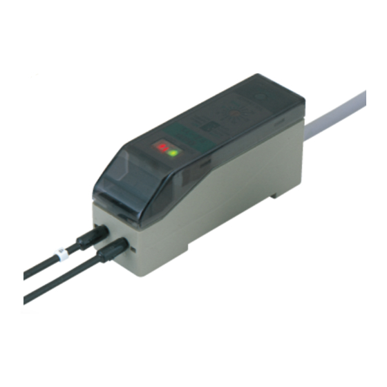
Color Detection Fiber Sensor Amplifier
FZ-10 Series
1
FUNCTIONAL DESCRIPTION
Fiber lock lever
POWER
OUT
Power indicator
(Green)
FZÐ11
LOCK
SET
AUTO
MANUAL
INVERSE
NORMAL
OFD
NON
8
10
6
12
4
14
FINE
TOLERANCE
Tolerance adjuster
TEACH
JAPAN
Description
Fiber lock lever
Locks or unlocks fiber cables.
Lights up when the power is ON,
Power indicator (Green)
blinks during auto-teaching.
Operation indicator (Red)
Lights up when the output is ON.
The teaching button is ineffective if the switch is set on 'LOCK',
Teaching protect switch
but is effective if the switch is set on 'SET'.
Manual-teaching is selected if the switch is set on 'MANUAL'.
Setting mode selection switch
Auto-teaching is selected if the switch is set on 'AUTO'.
Coincident-ON is selected if the switch is set on 'NORMAL'.
Output operation mode switch
Incoincident-ON is selected if the switch is set on 'INVERSE'.
The OFF-delay timer is ineffective if the switch is set on 'NON',
Timer operation mode switch
but is effective if the switch is set on 'OFD'.
Determines the tolerance of equivalence, with respect to the
Tolerance adjuster
reference color that the sensor has been taught, in 16 grades.
Teaches the sensor the target color as the criterion (reference
color.)
Teaching button
While the button is held, the sensor emits blue, red, and
green beams one after the other.
2
MOUNTING
How to mount the amplifier
Fit the rear part of the amplifier on the attached
amplifier mounting bracket (MS-DIN-3) or a
35mm width DIN rail.
Press down the front part of the amplifier on the
amplifier mounting bracket (MS-DIN-3) or the
35mm width DIN rail to fit it.
How to remove the amplifier
Push the amplifier forward.
Lift up the front part of the amplifier to remove it.
Note: Please take care that if the front part is lifted without pushing the amplifier for-
wards, the hooks on the rear portion of the mounting section are likely to break.
How to connect the fiber cables
Unlock the fiber lock lever by lower-
ing it.
Insert the beam-emitting fiber cable
tagged with the mark ' ' into the
beam-emitting part 'P', and the
beam-receiving fiber cable into the
beam-receiving part 'D'. They should
be inserted gradually until the posi-
tion where they stop. If the emitting
fiber cable and the receiving fiber
cable are reversely inserted, proper
operation cannot be obtained.
Lock the fiber lock lever to the origi-
nal position.
Notes: 1)
The fiber heads of the FD-L51 and / or the FD-L52 and / or the FD-L53 and
/ or the FD-L54 can be closely mounted together as long as their spots do
not overlap each other.
2)
Refer to the fiber's Instruction Manual for the fiber tip fitting method.
SEN TRONIC
AG
INSTRUCTION MANUAL
Operation indicator (Red)
Teaching protect
switch
Setting mode
selection switch
LOCK
SET
AUTO
MANUAL
INVERSE
NORMAL
Output operation
mode switch
OFD
NON
Timer operation
mode switch
Teaching button
Function
Both blink alternately
when a manual-teaching
error occurs.
Both blink simultaneous-
ly when the output is
short-circuited.
Fiber lock
lever
Beam-
emitting
part
Beam-receiving part
Fiber cable
Tag mark
Rugghölzli 2
CH - 5453 Busslingen
Produkte, Support und Service
Thank you very much for purchasing Panasonic products. Read this Instruc-
tion Manual carefully and thoroughly for the correct and optimum use of this
product. Kindly keep this manual in a convenient place for quick reference.
Never use this product as a sensing device for personnel pro-
tection.
In case of using sensing devices for personnel protection, use
products which meet laws and standards, such as OSHA, AN-
WARNING
SI or IEC etc., for personnel protection applicable in each re-
gion or country.
3
I/O CIRCUIT DIAGRAMS
NPN output type / FZ-11
Color code
D
T
r
100mA max.
Z
D
Internal circuit
Users' circuit
Symbols ... D
: Reverse supply polarity protection diode
Z
: Surge absorption zener diode
D
T
: NPN output transistor
r
PNP output type / FZ-11P
Color code
T
Z
r
D
100mA max.
D
Internal circuit
Users' circuit
Symbols ... D
: Reverse supply polarity protection diode
Z
: Surge absorption zener diode
D
T
: PNP output transistor
r
4
SETTING
During teaching, the FZ-10 series resolves the color projected by the
spot into red, green, and blue components which are processed as nu-
merical values and stored into the EEPROM memory. If, during teaching,
the spot area is not filled by one uniform color, such as
when the target objects are smaller than the spot area,
or are partly projected upon, then colors other than the
one you want to detect may also be sensed. Make sure
that objects fill the whole spot area during teaching, as
well as, sensing.
The taught data is saved in the EEPROM even when the sensor power
supply is switched off. However, the guaranteed rewrite operations are
limited to 100,000 times because of its lifetime.
To manipulate the DIP switches, use a pair of tweezers, etc., with a tip
width of 0.8mm approx.
Procedure
1
2
Setting reference
Setting output
color
operation
INVERSE
NORMAL
1. Setting reference color
Prepare a sample object bearing the target color you want to detect.
Choose manual teaching or auto-teaching.
Setting by manual-teaching
Teaching the reference color on a stationary object.
Set the tolerance adjuster at the 16th grade
(
mark) with the adjusting screwdriver.
Set the teaching protect switch on 'SET'.
Set the setting mode selection switch on
'MANUAL'.
Tel. +41 (0)56 222 38 18
Fax +41 (0)56 222 10 12
+
12 to 24V DC
10%
-
+
12 to 24V DC
10%
-
Emitting spot
Workpiece
3
4
Setting timer
operation
8
10
6
12
4
OFD
NON
14
FINE
8
10
6
12
4
FINE
14
Teaching protect
switch
LOCK
SET
AUTO
MANUAL
Setting mode
selection switch
mailbox@sentronic.com
www.sentronic.com
Advertisement
Table of Contents

Related Manuals for Panasonic FZ-10 Series


Summary of Contents for Panasonic FZ-10 Series
- Page 1 Teaches the sensor the target color as the criterion (reference color.) Teaching button During teaching, the FZ-10 series resolves the color projected by the While the button is held, the sensor emits blue, red, and green beams one after the other.
- Page 2 (Green) 3. Setting timer operation the reference color The FZ-10 series is incorporated with an OFF-delay timer fixed for 40ms * In case teaching is not properly done. approx. The OFF-delay timer operates when the timer operation mode The operation indicator (red) and the power indicator (green) blink alternately.
- Page 3 SPECIFICATIONS Type NPN output PNP output Item Model No. FZ-11 FZ-11P Applicable fibers FD-L51 (Note 1), FD-L52, FD-L53, FD-L54 Opaque or translucent object larger than the spot diameter of the Sensing object applicable fiber Supply voltage 12 to 24V DC 10% Ripple P-P 10% or less Current consumption 45mA or less NPN open-collector transistor...
Need help?
Do you have a question about the FZ-10 Series and is the answer not in the manual?
Questions and answers