Panasonic FX-502 Instruction Manual
Digital fiber sensor amplifier
Hide thumbs
Also See for FX-502:
- Instruction manual (4 pages) ,
- Instructions manual (13 pages) ,
- Instruction manual (9 pages)
Advertisement
Quick Links
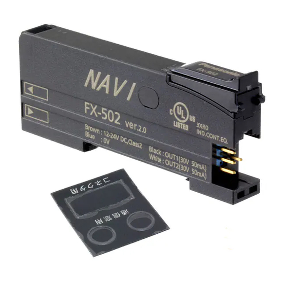
Digital Fiber Sensor Amplifier FX-502□
Thank you very much for purchasing Panasonic products.
Please read this Instruction Manual carefully and thoroughly for the correct and
optimum use of this product.
Kindly keep this manual in a convenient place for quick reference.
● Never use this product as a sensing device for personnel protection.
● In case of using sensing devices for personnel protection, use products which
meet laws and standards, such as OSHA, ANSI or IEC etc., for personnel
protection applicable in each region or country.
INTENDED PRODUCTS FOR CE MARKING
1
● This product complies with the following standards / regulations.
<EU Directive>
EMC Directive 2004/108/EC
<Standards in US / Canada>
ANSI/UL 60947-5-2, CAN/CSA C22.2 No.14
<Regulations in Korea>
S1-G-1-2009, S2-W-5-2009
● Caution about UL recognition
In case requiring conformity of UL listing mark or C-UL listing mark, USe class
2 power supply unit.
2
PART DESCRIPTION
Sensing output 2
UP key
selection indicator
• Teaching
(Yellow)
• Threshold value
Sensing output 1
fine adjustment
selection indicator
• Select setting items
(Yellow)
Sensing output 1
Digital display
operation indicator
(Green / Red)
(Orange)
MODE indicator: L / D (Yellow)
Sensing output 2
MODE indicator: CUST (Yellow)
operation indicator
(Orange)
MODE indicator: PRO (Yellow)
<Reference>
Pressing down SET key + MODE key for 3 sec: Set key lock or release key lock
3
MOUNTING
How to connect
1. Fit the rear part of the mounting sec-
tion of the amplifier on a DIN rail.
2. Press down the rear part of the
mounting section of the unit on the
DIN rail and fit the front part of the
mounting section to the DIN rail.
How to remove
1. Push the controller forward.
2. Lift up the front part of the amplifier
to remove it.
How to connect the fiber cable
Be sure to fit the attachment to the fibers first before inserting the fibers to the
amplifier. For details, refer to the instruction manual enclosed with the fibers.
1. Snap the fiber lock lever down till it
stops completely.
2. Insert the fiber cables slowly into the
inlets until they stops. (Note)
3. Return the fiber lock lever to the
original position till it stops.
Note: With the coaxial reflective type fiber, such as, FD-G4
or FD-FM2, insert the single core fiber cable into the
beam-emitting inlet "P" and the multi-core fiber cable
into the beam-receiving inlet. If they are inserted in
reverse, the sensing performance will deteriorate.
INSTALL MORE AMPLIFIER OF SERIES CONNECTION TYPE
4
● Make sure that the power supply is OFF while adding or removing the series connection type.
● In case 2 or more the series connection types are connected in cascade, make
sure to mount them on a DIN rail.
● 11 the series connection types using sub cables can be added to an amplifier
using a main connection cable.
● When connecting 2 or more the series connection types in cascade, use the
sub cable (optional) for the second series connection type onwards.
INSTRUCTION MANUAL
MJE-FX502 No.0015-33V
WARNING
SET key
DOWN key
• Teaching
• Teaching
• C o n f i r m s e t t i n g
• Threshold value fine
contents
adjustment
• Select setting items
MODE key
• Select Modes
• Cancel during setting
• Select sensing output 1/2
by pressing long
2. Press down
35mm width DIN rail
1. Push forward
2. Lift up
3. Return
1. Snap
Fiber lock lever
Fiber for emitter
2. Insert
Fiber for
receiver
For mounting and removing the amplifier, refer to "
How to cascade
1. Mount the amplifiers, one by one,
on the DIN rail.
2. Slide the amplifiers next to each
other, and connect the quick-
connection cables.
3. Mount the end plates MS-DIN-E
(optional) at both the ends to hold
the amplifiers between their flat
sides.
4. Tighten the screws to fix the end
plates.
How to Remove
1. Loosen the screws of the end
plates.
2. Remove the end plates.
3. Slide the amplifiers and remove
them one by one.
5
I/O CIRCUIT DIAGRAMS
<FX-502>
<FX-502P>
Note: The quick-connection sub cable does not incorporate +V (brown) and 0V (blue). The power is supplied from
the connector of the main cable.
<Terminal arrangement>
1
2
3
OPERATION PROCEDURE
6
● The sensing output can be switched to sensing output 1 or sensing output 2
by holding down the mode key.
● The changed settings are not stored if turning the power OFF while setting.
1. Fit
Therefore, confirm the settings by pressing the SET key before turning the
power OFF.
● When turning ON the power, RUN mode is displayed and the digital display
shows the threshold value (green) and the incident light intensity (red).
<RUN mode>
<Sensing output operation mode>
<CUSTOM mode>
<PRO mode>
<RUN mode>
End plate
MS-DIN-E (Optional)
(Brown) +V (Note)
(White) Sensing output 2 / External input
(Black) Sensing output 1
(Blue) 0V (Note)
(Brown) +V (Note)
(Black) Sensing output 1
(White) Sensing output 2 / External input
(Blue) 0V (Note)
Terminal No.
Terminal name
1
+V
2
Sensing output 1
4
3
Sensing output 2 / External input
4
0V
• Displays threshold value (green) and incident light intensity (red).
• Teaching, threshold value fine adjustment and key lock function can be set.
• For setting method of each function, refer to "
MODE," "
THRESHOLD VALUE FINE ADJUSTMENT FUNC-
TION," or "
KEY LOCK FUNCTION."
• Select either Light-ON or Dark-ON.
• For the setting, refer to "
MODE."
• The default setting is "
• An item set in CUSTOM mode (Response time setting, Emission
power setting and Hysteresis setting) is displayed.
• For details, refer to "
• The default setting is "
• Advanced setting can be done.
• For the setting, refer to "
MOUNTING."
Sub cable
(Optional)
Communication
window
Slide
Main cable
(Optional)
End plate
MS-DIN-E
(Optional)
Slide
Load
+
12 to 24V DC
%
-
+
12 to 24V DC
%
-
Load
TEACHING
SENSING OUTPUT OPERATION
" (Light-ON).
CUSTOM MODE."
" (response time setting).
PRO MODE."
Advertisement

Related Manuals for Panasonic FX-502


Summary of Contents for Panasonic FX-502
-
Page 1: Operation Procedure
MJE-FX502 No.0015-33V 2. Slide the amplifiers next to each other, and connect the quick- Communication Thank you very much for purchasing Panasonic products. window connection cables. Please read this Instruction Manual carefully and thoroughly for the correct and End plate 3. - Page 2 TEACHING MODE 1-point teaching [Window comparator mode (except sensing output 2) / Hysteresis mode] ● Be sure that detection may become unstable depending on the use environ- ● This is method to set the shift amount to the desired value and to set the ment in teaching if less margin is applied.
- Page 3 THRESHOLD VALUE FINE ADJUSTMENT FUNCTION PRO MODE ● Set fine adjustment of threshold value in RUN mode. ● When MODE indicator: PRO (yellow) lights up, PRO mode can be set. ● Also, the threshold value fine adjustment function can be used in forced ON ●...
-
Page 4: Error Indication
Description Remedy right side to the main amplifier as follows. indication However, in case using data bank loading / saving, use FX-502□ or FX-505□-C2 EEPROM is broken or reached the end of its working life. Please contact our office. as main amplifier.
Need help?
Do you have a question about the FX-502 and is the answer not in the manual?
Questions and answers