
Subscribe to Our Youtube Channel
Related Manuals for Deye SUN-60K-G01P3-EU-AM8-LV


Summary of Contents for Deye SUN-60K-G01P3-EU-AM8-LV
- Page 1 Grid-connected PV Inverter SUN-��K-G��P�-EU-AM�-LV SUN-��K-G��P�-EU-AM�-LV SUN-��K-G��P�-EU-AM�-LV User Manual...
-
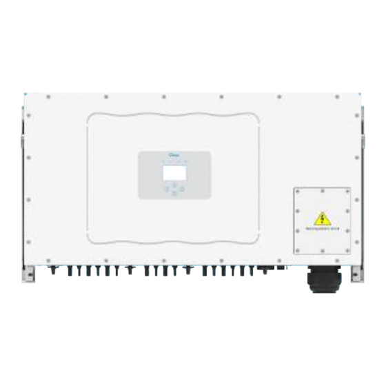
Page 2: Appearance Introduction
�. Introduction ���������������������� - 1 - 1.1 Appearance Introduction �������������������� - 1 - 1.2 Labels description ������������������������ - 1 - 1.3 Parts list �������������������� - 2 - 1.4 Product handling requirements ���������������� - 3 - �. Safety warnings and instructions ���������������... -
Page 3: Statistics Information
�. Zero-export function via energy meter ����������� - 19 - 7.1 Multiple strings and parallel connection meters ��������� - 29 - 7.2 How to browse the load power of your PV grid-tieplant on monitoring platform? - 39 - �. General Operation �����������������... -
Page 4: About This Manual
Documents must be stored carefully and be available at all times. Contents may be periodically updated or revised due to product development. The information in this manual is subject to The latest manual can be acquired via service@deye.com.cn change without notice. �. Introduction �.�... - Page 5 �.� Parts list Please check the following table, to see whether all the parts are included in the package: Mounting stainless steel screws M4×12 Grid-tied PV String Inverter Wall mounting bracket x 1 x 11 DC+/DC- Plug connectors Stainless steel anti-collision including metal terminal bolt M12×60 Wrench x 2...
- Page 6 �.� Product handling requirements Lift the inverter out of the packing box and transport it to designated installation location. transport CAUTION: Improper handling may cause personal injury! • Arrange an appropriate number of personnel to carry the inverter according to its weight, and installation personnel should wear protective equipment such as anti-impact shoes and gloves.
-
Page 7: Safety Instructions
�.� Safety instructions Warning: Electrical installation of the inverter must conform to the safety operation rules of the country or local area. Warning: Inverter adopts non-isolated topology structure, hence must insure DC input and AC output are electrical isolated before operating the inverter. Shock Hazard: Prohibit disassembling inverter case, there existing shock hazard, which may cause serious injury or death, please ask qualified person to repair. - Page 8 �. Operation Interface �.� Interface View Pic 3.1 Front panel display �.� Status Indicator The inverter panel has 4 indicators, the left one is dc output indicators, green indicates normal DC input. Beside is the AC indicator, green indicating normal ac connection. Beside the AC indicator is the operating indicator, green indicating normal output.
- Page 9 �.� Buttons There are four buttons on the inverter panel:Above is Up and increase button(UP), Below is down and decrease button(DOWN), Left is ESC button(ESC), Right is Enter button(ENTER). Achieving below functions by the four buttons: Page turning (use UP and DOWN button) ●...
- Page 10 �. Product installation �.� Select installation location To select a location for the inverter, the following criteria should be considered: WARNING: Risk of fire Do not install the inverter in areas containing highly flammable materials or gases. ● Do not install the inverter in potentially explosive atmospheres. ●...
- Page 11 Install on a wall or strong structure capable of bearing the weight. ● Install vertically with a maximum incline of +15°. If the mounted inverter is tilted to an ● angle greater than the maximum noted, heat dissipation can be inhibited, and may result in less than expected output power.
- Page 12 ≥500mm ≥500mm Pic 4.3 Installation Gap �.� Mounting bracket of inverter Pic 4.4 Mounting bracket dimensions - 09 -...
-
Page 13: Inverter Installation
�.� Installations Tools Installation tools can refer to the following recommended ones. Also, use other auxiliary tools on site. table 4-1 Tool specification Protective goggles Earplugs Anti-dust mask Work gloves Work shoes Utlity Knife Slotted screwdriver Cross screwdriver Percussion drill Pliers Marker Level... - Page 14 �. Electrical Connection �.� DC input terminal connection 1. Switch the Grid Supply Main Switch(AC)OFF. 2. Switch the DC lsolator OFF. 3. Assemble PV input connector to the inverter. Warning: When using PV modules, please ensure the PV+ & PV- of solar panel is not connected to the system ground bar.
- Page 15 The steps to assemble the DC connectors are listed as follows: a) Strip off the DC wire about 7mm, disassemble the connector cap nut (see picture 5.3). Pic 5.3 Disassemble the connector cap nut b) Crimping metal terminals with crimping pliers as shown in picture 5.4. Pic 5.4 Crimp the contact pin to the wire c) Insert the contact pin to the top part of the connector and screw up the cap nut to the top part of the connector.
- Page 16 Please use its own DC power connector from the inverter accessories. Do not interconnect the connectors of different manufacturers.Max. DC input current should be 20A. if exceeds, it may damage the inverter and it is not covered by Deye warranty. �.� AC terminal connection Torque...
- Page 17 AC wire installation method: 1) Remove the 10 screws on the inverter junction box and remove the junction box cover in Pic 5.7. After removing the junction box, you can see the terminals of the inverter. The default is 4 digits as shown in Pic 5.8.
- Page 18 3) Screw the AC connection cover back to the shell and tighten all the screws to tighten the waterproof protection connector, as shown in Pic 5.11 Pic 5.11 Tighten the AC junction box �.�.� Recommended current protector specifications Inverter Rated voltage Rated output power (...
- Page 19 The installation of the shell ground wire is shown as Pic 5.12. Pic 5.12 The installation of the shell ground wire Recommend Wire Size Cable(mm²) Model Torque value(max) copper cable SUN-60K-G01P3-EU-AM8-LV 25mm² 25mm² 2AWG 16.9Nm SUN-70K-G01P3-EU-AM8-LV 1AWG 35mm² 35mm²...
- Page 20 �.� Inverter monitoring connection Inverter has the function of wireless remote monitoring inverter. The inverter has Wifi function and Wifi Plug in the accessories is used to realize the connection between the inverter and the network. The operation, installation, networking, APP download are detailed in the WIFI PLUG instructions.
-
Page 21: Start Up The Inverter
�.�.� Configuration of datalogger For the configuration of datalogger, please refer to illustrations of the datalogger. �. Start up and Shut off Ensure that the inverter meets the following conditions before starting the inverter, otherwise it may cause fire or damage to the inverter without quality assurance, at the same time the situation on our company does not undertake any responsibility. - Page 22 �. Zero-export function via energy meter There're four kinds of energy meters for this series inverter. First type is Eastron SDM630-Mod- bus V2 which is able to measure the Max. 200A current directly. More details please refer to Pic 7.1 & 7.4. For the Eastron SDM630 MCT 40mA, it needs external CT to measure the current. The CT power range is from 5A-2000A.
- Page 23 1 2 3 4 5 6 7 8 Eastron (�,�,�,�) (�,�,�,�) B A G RS ��� RS 485 B RS 485 A Eastron SDM630-Modbus V2 Pic 7.1 Eastron meter Inverter Solar Panel array AC Breaker RS 485 Male connector Home load VCC_5V 485_B N L3 L2 L1...
- Page 24 1 2 3 4 5 6 7 8 Eastron (�,�,�,�) (�,�,�,�) B A G RS ��� RS 485 B RS 485 A Eastron SDM630-Modbus V2 Pic 7.3 Eastron meter Inverter Solar Panel array AC Breaker RS 485 Male connector Home load VCC_5V 485_B N L3 L2 L1...
- Page 25 9 1 0 11 1 2 1 3 1 4 1 5 1 6 1 7 1 8 1 9 2 0 Eastron 1 2 3 4 15 16 17 18 19 20 Grid voltage Auxiliary Current inputs sampling power supply ��...
- Page 26 9 1 0 11 1 2 1 3 1 4 1 5 1 6 1 7 1 8 1 9 2 0 Eastron 1 2 3 4 15 16 17 18 19 20 Grid voltage Auxiliary Current inputs sampling power supply ��...
- Page 27 (�,�,�,��) (�,�,�,��) Three-Phase Smart Meter RS ��� CHNT DTSU666 Pic 7.9 CHNT meter Solar Panel array Inverter AC Breaker RS 485 Male connector Home load L1 L2 L3 N VCC_5V 485_B RS 485 Female connector Three-Phase Smart Meter meter 485_A L1 L2 L3 N 485_A 485_B...
- Page 28 (�,�,�,��) (�,�,�,��) Three-Phase Smart Meter RS ��� CHNT DTSU666 Pic 7.11 CHNT meter Solar Panel array Inverter AC Breaker RS 485 Male connector L1 L2 L3 N Home load VCC_5V 485_B RS 485 Female connector Three-Phase Smart Meter meter 485_A L1 L2 L3 N 485_A 485_B...
- Page 29 6 9 10 1314 16171921 Three-Phase Smart Meter 230/400V, 3~100A/40mA 50/60Hz 24 25 Phase A current =5.000A 13 14 16 17 19 21 RS485 CHNT DTSU666 Phase B current =5.001A 3x230/400V 100A/40mA Pic 7.13 CHINT meter Phase C current =5.002A Solar Panel array Inverter AC Breaker...
- Page 30 6 9 10 1314 16171921 Three-Phase Smart Meter 230/400V, 3~100A/40mA 50/60Hz 24 25 Phase A current =5.000A 13 14 16 17 19 21 RS485 CHNT DTSU666 Phase B current =5.001A 3x230/400V Pic 7.15 CHINT meter Phase C current =5.002A Inverter Solar Panel array AC Breaker RS 485...
- Page 31 1. Press Enter button on the LCD panel in the main interface into the menu options, select [parameter setting] to enter setup submenu, and then select [run param], at this time please input the default password 1234 through pressing the button [up down, enter], enter the operation parameter setting interface, shown as picture 7.17.
-
Page 32: Menu Setting
�.� Multiple strings and parallel connection meters This application is that when the string inverters work in parallel, there is only one power grid and one load, and only one meter can be connected to prevent reverse current, so only this many-to-one anti-reverse current connection can be connected. - Page 33 Name Description Range AVG: Average power of three phase is zero exported. AVG/MIN Exp_Mode MIN: Phase with minimum load power is zero exported, while the other two phase may be in purchase mode. CT ratio of power grid side meter when extern 1-1000 CT_Ratio CT is applied.
- Page 34 1 2 3 4 5 6 7 8 Eastron (�,�,�,�) (5,6,7,8) B A G RS 485 RS 485 B RS 485 A Eastron SDM���-Modbus V� Pic �.�� Eastron meter Master(Mst) Grid L1 L2 L3 N RS��� 485_B 485_A VCC_5V 485_B RS 485 Slave2(Slv2) Female connector...
- Page 35 1 2 3 4 5 6 7 8 Eastron (�,�,�,�) (5,6,7,8) B A G RS 485 RS 485 B RS 485 A Eastron SDM���-Modbus V� Pic �.�� Eastron meter Generator Master(Mst) L1 L2 L3 N RS��� 485_B 485_A VCC_5V 485_B RS 485 Slave2(Slv2) Female connector...
- Page 36 9 1 0 11 1 2 1 3 1 4 1 5 1 6 1 7 1 8 1 9 2 0 Eastron 1 2 3 4 15 16 17 18 19 20 Grid voltage Auxiliary Current inputs sampling power supply ��...
- Page 37 9 1 0 11 1 2 1 3 1 4 1 5 1 6 1 7 1 8 1 9 2 0 Eastron 1 2 3 4 15 16 17 18 19 20 Grid voltage Auxiliary Current inputs sampling power supply ��...
- Page 38 (�,�,�,��) (�,�,�,��) Three-Phase Smart Meter RS ��� CHNT DTSU666 Pic �.�� CHNT meter Master(Mst) AC Breaker Solar Panel array Slave1(Slv1) AC Breaker Solar Panel array Slave2(Slv2) AC Breaker Solar Panel array AC Breaker load VCC_�V ���_B RS ��� Female connector ���_A Master(Mst) RS���...
- Page 39 (�,�,�,��) (�,�,�,��) Three-Phase Smart Meter RS ��� CHNT DTSU666 Pic �.�� CHNT meter Master(Mst) AC Breaker Solar Panel array Slave1(Slv1) AC Breaker Solar Panel array Slave2(Slv2) AC Breaker Solar Panel array AC Breaker load VCC_�V ���_B RS ��� Female connector ���_A Master(Mst) RS���...
- Page 40 6 9 10 1314 16171921 Three-Phase Smart Meter 230/400V, 3~100A/40mA 50/60Hz 24 25 Phase A current =5.000A 13 14 16 17 19 21 RS485 CHNT DTSU666 Phase B current =5.001A 3x230/400V Pic �.�� CHINT meter Phase C current =5.002A Master(Mst) AC Breaker Solar Panel array Slave1(Slv1)
- Page 41 6 9 10 1314 16171921 Three-Phase Smart Meter 230/400V, 3~100A/40mA 50/60Hz 24 25 Phase A current =5.000A 13 14 16 17 19 21 RS485 CHNT DTSU666 Phase B current =5.001A 3x230/400V Pic �.�� CHINT meter Phase C current =5.002A Master(Mst) AC Breaker Solar Panel array Slave1(Slv1)
- Page 42 �.� How to browse the load power of your PV grid-tie plant on monitoring platform? If you want to browse load power of the system and how much energy (KWH) does it export to grid(inverter output power is used to power the load firstly and then the surplus energy will feed into grid).
- Page 43 Secondly, go to plant page, if it shows the PV power, load power and grid power, which means the configuration is correct. String inverter Solar Station Back to Plants list ID����� Compare Edit More Partially Offline No Alerts Last update ����/��/�� ��:��:�� UTC+��:�� String inverter Solar Sta...
- Page 44 �. General Operation During normal operation, the LCD shows the current status of the inverter, including the current power, total generation, a bar chart of power operation and inverter ID, etc. Press the Up key and the Down key to see the current DC voltage, DC current, AC voltage, AC current, inverter radiator temperature, software version number and Wifi...
- Page 45 ActiveP Q-Mode ReactP Exp_Mode Fun- ISO CT_Ratio 0 Fun RCD FeedIn SelfCheck Shunt ShuntQTY Island Generator G.CT Meter G.MFR G.FeedIn Limiter Setup G.Cap Feed-in Running param MPPT Num OF-Derate UF-Uprate WGRa WGraStr HardLim VRef SoftLim PowerLim VoltageRT Sunspec OK Cancel - 42 -...
- Page 46 *Note: These parameters will be avaiable after the meter is INMETRO connected successfully. Otherwise, it won't show. EN50549 Attention: For running param detail on the LCD display, please EN50438 refer to the official Deye website https://www.deyeinverter.com IEC61727 CUSTOM VDE_4105 UTE_C15 RD1699...
- Page 47 �.� The initial interface From the initial interface, you can check power, daily generation, gross generation, invertert ID , model and time. �.�Kw SN-�� ����-��-�� ��:��:�� P - �� Kw Power: ��.��Kw Day : ���kWh Total : �� MWh State : Standby �...
- Page 48 Grid Ua : ���.�V Ia : �.�A Grid Freq : ��.��Hz PF : �.��� Pic 8.3 AC running state information You can check the three phase voltage, current, and grid frequency. Total DC Power: �.���W Lcd���� Inv���� Pic 8.4 Inverter firmware version You can check the inverter LCD software Ver0196 and Control Software Version Ver1400.
- Page 49 �.�.� Main Menu There are four submenu in the Main Menu. MENU Statistics 《 Fault Record ON/OFF Setup Pic 8.6 Main Menu �.� Statistics information There are five submenu in the statistics. MENU》 Statistics E-Day E-History E-Month Test Data 《 E-Year Pic 8.7 Statistics Into each submenu through cursor.
- Page 50 MENU》 Statistics》 E-Day <����-��-��> ��MWh � � �� �� �� Pic 8.8 E-Day MENU》 Statistics》 E-Month ����-�� �-�� �� �� <> ��MWh �� �� �� �� �� �� �� �� �� �� Pic 8.9 E-Month MENU》 Statistics》 E-Year <����> ���KWh ��...
- Page 51 MENU》 Statistics》 E-History <����-����> �KWh �� �� �� �� �� �� �� �� �� �� Pic 8.11 E-History This information is for technician’s reference. PV� ����� �k� ����� ���� PV� ����� �k� ����� ��� : ���� ����� �k� ����� ��� ����...
- Page 52 �.� ON/OFF setting MENU》 ON/OFF Turn ON Turn OFF 《 Pic 8.14 ON/OFF setting Into each submenu through cursor. MENU》 ON/OFF》 Turn ON 《 Turn ON Cancel Pic 8.15 ON set MENU》 ON/OFF》 Turn OFF 《 Turn OFF Cancel Pic 8.16 OFF set - 49 -...
-
Page 53: Menu Setup
�.� Parameter setting Setting includes system param, run param, protect param, comm.. param. All of these information for maintenance reference. MENU》 Setup System Param 《 Param Protect Param Comm. Param Pic 8.17 Setting �.�.� System Param System Param MENU》 Setup 》 Time Set Language Set Display Set... - Page 54 �.�.�.� Time Set Time Set ����-��-�� ��:��:�� Cancel Pic 8.18 System Param �.�.�.� Language Set Lauguage Set 简体中文 English 《 Polski Pic 8.19 Lauguage set �.�.�.� Display Set Display Set Brightness Keep 《 Delay time ��S Cancel Pic 8.20 Display set - 51 -...
-
Page 55: Factory Data Reset
�.�.�.� Factory data reset Factory data reset Confirm to reset 《 Cancel Pic 8.21 Factory data reset set �.�.�.� Setting Restore Setting Restore Confirm to restore 《 Cancel Pic 8.22 Factory data reset set Warning: Password required-- only for access-authorized engineer. Un-authorized access may avoid the warranty. - Page 56 �.�.� Protect Param MENU》 Setup》 Protect Param GridStandard 《 Advanced Cancel Pic 8.23 Protect Param Warning: Engineer only. Standard Brazil EN�����-�-PL EN�����-� IEC����� Custom 《 VDE���� Cancel Standard VDE���� Spain CEI � �� 《 G�� G�� NBT�����-B Cancel - 53 -...
- Page 57 Standard Australia-A Australia-B Australia-C 《 New Zealand Cancel Standard Norway Switerland R�� 《 CEI-��� Cancel Pic 8.24 “Standard” - VoltageTriping Tov_� ����ms OV_� ���.�V Tov_� ����ms OV_� ���.�V OV_� ���.�V Tov_� ����ms UV_� ���.�V Tuv_� ����ms Tuv_� ����ms UV_� ���.�V Tuv_�...
- Page 58 - FrequencyTriping Tof_� ����ms OF_� ��.��Hz Tof_� ����ms OF_� ��.��Hz OF_� ��.��Hz Tof_� ����ms Tuf_� ����ms UF_� ��.��Hz Tuf_� ����ms UF_� ��.��Hz Tuf_� ����ms UF_� ��.��Hz Cancel - Miscellaneous �.�% Vrc_H �.�V Vrc_L �.�V Frc_H �.�Hz Frc_L �.�Hz VGrid ���/���V OV��Min Cancel Pic 8.25 “Advanced”...
- Page 59 �. Repair and Maintenance String type inverter doesn’t need regular maintenance. However, debris or dust will affect heat sink’s thermal performance. It is better to clean it with a soft brush. If the surface is too dirty and affect the reading of LCD and LED lamp, you can use wet cloth to clean it up. High Temperature Hazard: When the device is running, the local temperature is too high and the touch can cause burns.
-
Page 60: Error Code
Check the solar panel output connection. Failure in reading memory (EEPROM). Restart the inverter if the Read the memory error fault still exists, contact your installer or Deye service. Failure in writing memory (EEPROM). Restart the inverter if the Write the memory error fault still exists, contact your installer or Deye service. - Page 61 The DC busbar is unbalanced 2. Restart the inverter, if the fault still exists, contact your installer or Deye service. DC end insulation error Hardly appear the code. Never ever happened so far. Inverter 1 DC high fault Hardly appear the code.
- Page 62 1. Check AC current sensor and its circuit. AC over current(one cycle) 2. Restart the inverter, if the fault still exists, contact your installer or Deye service. DC over current Hardly appear the code. Never ever happened so far. Check the AC voltage protection setting. And Check if the AC AC Line W,U over voltage cable is too thin.Check the voltage difference between LCD and...
- Page 63 Error code Description Ongrid - Three Phase AC grid V over current Hardly appear the code. Never ever happened so far. AC grid W over current Hardly appear the code. Never ever happened so far. Reactor A phase over current Hardly appear the code.
-
Page 64: Equipment Protection
��.Specification SUN-��K-G��P� SUN-��K-G��P� SUN-��K-G��P� Model -EU-AM�-LV -EU-AM�-LV -EU-AM�-LV PV String Input Data 112.5 Max. PV Input Power(kW) Max. PV Input Voltage(V) Start-up Voltage(V) MPPT Voltage Range(V) 200-700 Full Load MPPT Voltage Range(V) 290-700 330-700 360-700 Rated PV Input Voltage(V) Max. Input Short Circuit Current (A) 60+60+60+60+60+60+60+60 Max. -
Page 65: General Data
· Low Voltage Directive 2014/35/EU (LVD) · Restriction of the use of certain hazardous substances 2011/65/EU(RoHS) NINGBO DEYE INVERTER TECHNOLOGY CO., LTD. confirms herewith that the products described in this document are in compliance with the fundamental requirements and other relevant provisions of the above mentioned directives. -
Page 66: Eu Declaration Of Conformity
SUN-120K-G01P3-EU-AM8;SUN-125K-G01P3-EU-AM8;SUN-130K-G01P3-EU-AM8; SUN-135K-G01P3-EU-AM8;SUN-136K-G01P3-EU-AM8;SUN-60K-G01P3-EU-AM8-LV; SUN-70K-G01P3-EU-AM8-LV;SUN-75K-G01P3-EU-AM8-LV; Name and address of the manufacturer: Ningbo Deye Inverter Technology Co., Ltd. No. 26 South YongJiang Road, Daqi, Beilun, NingBo, China This declaration of conformity is issued under the sole responsibility of the manufacturer. Also this product is under manufacturer’s warranty. - Page 67 Add. : No.�� South YongJiang Road, Daqi, Beilun, NingBo, China. Tel. : +�� (�) ��� ���� ���� Fax. : +�� (�) ��� ���� ���� E-mail. : service@deye.com.cn Web. : www.deyeinverter.com...
Need help?
Do you have a question about the SUN-60K-G01P3-EU-AM8-LV and is the answer not in the manual?
Questions and answers