Table of Contents
Advertisement
Available languages
Available languages
Quick Links
Advertisement
Chapters
Table of Contents

Related Manuals for Cebora 502


Summary of Contents for Cebora 502
- Page 1 MANUALE DI ISTRUZIONI PER KIT INTERFACCIA CNC E MODBUS RS485 ART. 502 Istruzioni in lingua originale EN INSTRUCTION MANUAL FOR CNC INTERFACE & MODBUS RS485 KIT, ART. 502 Translation of the original instructions 3301291 3301345-IT 3301291 3301345 16/02/2023 03/05/2024...
-
Page 2: Table Of Contents
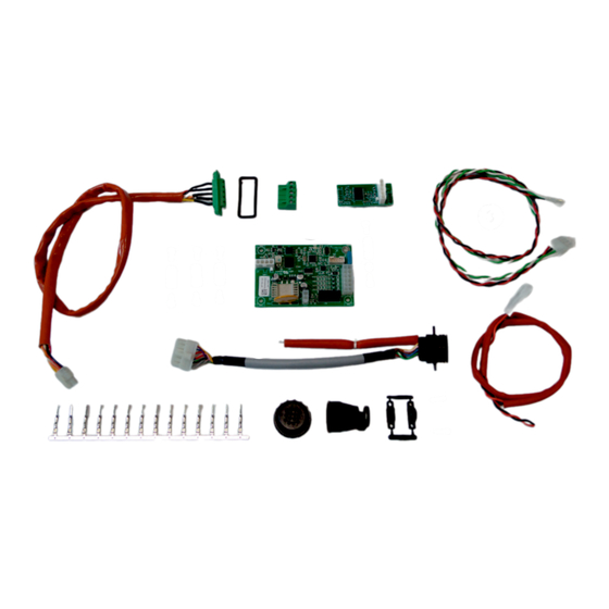
COMPOSIZIONE KIT ������������������������������������������������������������������������������������������������������������������������������������������� 4 SCOPO ������������������������������������������������������������������������������������������������������������������������������������������������������������������ 4 INSTALLAZIONE �������������������������������������������������������������������������������������������������������������������������������������������������� 5 PREDISPOSIZIONE GENERATORE ������������������������������������������������������������������������������������������������������������������� 6 PIN OUT CONNETTORE CNC ���������������������������������������������������������������������������������������������������������������������������� 7 PIN OUT CONNETTORE MODBUS �������������������������������������������������������������������������������������������������������������������� 7 SCHEMA ELETTRICO ART� 603 + ART� 502 ���������������������������������������������������������������������������������������������������� 16 LISTA DEI REGISTRI MODBUS ������������������������������������������������������������������������������������������������������������������������� 17 3301291 3301345-IT... - Page 3 Il presente manuale è parte della documentazione complessiva ed è valida soltanto in combinazione con i seguenti documenti parziali consultabili nella sezione Assistenza-Documentazione del sito welding�cebora�it 3301151 Avvertenze Generali 3301329 Manuale istruzioni generatore IMPORTANTE - Prima dell’utilizzo dell’apparecchio leggere attentamente e comprendere le indicazioni contenute nel manuale Avvertenze Generali cod.3301151 e nel presente manuale.
-
Page 4: Descrizioni Generali
DESCRIZIONI GENERALI Il presente Manuale Istruzioni si riferisce al Kit per Interfaccia CNC e Modbus RS485, art. 502, ed è stato preparato allo scopo di istruire il personale addetto all'installazione, al funzionamento ed alla manutenzione dell’impianto plasma. Deve essere conservato con cura, in un luogo noto ai vari interessati, dovrà essere consultato ogni qual volta vi siano dubbi ed impiegato per l'ordinazione delle parti di ricambio dovrà... -
Page 5: Installazione
ATTENZIONE! Le operazioni di installazione riportate di seguito devono essere eseguite solo da personale qualificato. Tutti i collegamenti elettrici devono essere effettuati nel pieno rispetto della legge antinfortunistica vigente. Per i seguenti punti, fare riferimento al par.3 COMPOSIZIONE KIT e allo schema elettrico art.603 + 502 INTERFACE Fig� 2 ♦... -
Page 6: Predisposizione Generatore
PREDISPOSIZIONE GENERATORE Completata l’installazione del Kit Interfaccia CNC e Modbus RS485, art. 502, occorre predisporre la scheda display del generatore affinchè sia riconosciuto il kit. In particolare, predisporre i dip switch SW1 come segue: Art.502 Dip-switch SW1 Fig. 12 Fig.12a art.502 non presente Fig.12b art.502 presente... -
Page 7: Pin Out Connettore Cnc
Cutting – Fast Restart PIN OUT CONNETTORE MODBUS Il Kit Interfaccia CNC e Modbus RS485, art. 502, permette la comunicazione seriale con un controllo esterno utilizzando il protocollo di comunicazione seriale Modbus. In allegato alle presenti istruzioni, la lista dei registri Modbus. - Page 8 POWER SOURCE SETUP ���������������������������������������������������������������������������������������������������������������������������������� 12 PIN OUT CNC CONNECTOR ����������������������������������������������������������������������������������������������������������������������������� 13 PIN OUT MODBUS CONNECTOR ������������������������������������������������������������������������������������������������������������������� 13 ART� 603 + ART� 502 ELECTRICAL DIAGRAM ������������������������������������������������������������������������������������������������ 16 LIST OF MODBUS REGISTERS ����������������������������������������������������������������������������������������������������������������������� 17 CNC INTERFACE & MODBUS RS485 KIT, ART. 502...
- Page 9 This manual is part of the overall documentation and is invalid unless it is used in conjunction with the following parts of the documentation that you can consult in the Support-Documentation section of the website welding.cebora.it: 3301151 General warnings 3301329...
-
Page 10: General Descriptions
GENERAL DESCRIPTIONS This Instruction Manual refers to the CNC and Modbus RS485 Interface Kit, art. 502, and has been prepared for the purpose of instructing the personnel responsible for the installation, operation and maintenance of the plasma system. It must be carefully stored, in a place known to the various interested parties, it must be consulted whenever there are doubts and used for ordering spare parts it must follow the entire operational life of the machine. -
Page 11: Installation
INSTALLATION The following indications refer to the "Installation figures" and the "ART. 603 + 502 INTERFACE" electrical diagram available at the end of this manual. For any further information, consult the power source Instruction Manual. WARNING! The installation operations below must be carried out only by qualified personnel. -
Page 12: Power Source Setup
POWER SOURCE SETUP The installation of the CNC and Modbus RS485 Interface Kit, art. 502, the power source display board must be set up so that the kit is recognised. In particular, set the SW1 dip switches as follows: Art.502 Dip-switch SW1 Fig. -
Page 13: Pin Out Cnc Connector
Cutting – Fast Restart PIN OUT MODBUS CONNECTOR The CNC and Modbus RS485 Interface Kit, art. 502, allows serial communication with an external control using the Modbus serial communication protocol. Attached to these instructions is the list of Modbus registers. - Page 14 FiG. 1 FiG. 2 FiG. 3 FiG. 4 FiG. 5 FiG. 6 FiG. 7 FiG. 8...
- Page 15 FiG. 9 FiG. 10 FiG. 11 FiG. 12...
-
Page 16: Schema Elettrico Art� 603 + Art� 502
SCHEMA ELETTRICO ART� 603 + ART� 502 ART� 603 + ART� 502 ELECTRICAL DIAGRAM... -
Page 17: Lista Dei Registri Modbus
LISTA DEI REGISTRI MODBUS LIST OF MODBUS REGISTERS Address Function Description Unit Read the ID of the SYNCH torch, torch lead and plasma power supply Torch and plasma power supply identification 0x3000 High byte: torch ID Low byte: power source ID (1=601, 2=602, 3=603) Read the permitted plasma power supply settings Permitted operating mode setting High byte: mode high (0x00) - Page 18 Read the maximum current of the torch 0x303C Nominal current Read the name of the torch 0x3048:0x304D The 12-character name (bytes from 0 to 11) Write operating settings and put the plasma power supply into remote control mode 0x3080 Operating mode setting (see 0x3001) 0x3081 Output current setting 0x3082...
- Page 20 CEBORA S�p�A - Via Andrea Costa, 24 - 40057 Cadriano di Granarolo - BOLOGNA - Italy Tel. +39.051.765.000 - Fax. +39.051.765.222 www.cebora.it - e-mail: cebora@cebora.it...
Need help?
Do you have a question about the 502 and is the answer not in the manual?
Questions and answers