Advertisement
Available languages
Available languages
Quick Links
CEBORA S.p.A.
MANUALE DI ISTRUZIONI DELL'INTERFACCIA ANALOGICA
IT
RAI448, PER IMPIANTI DI SALDATURA ROBOTIZZATI.
(MIG-TIG = Art. 448.00).
INSTRUCTIONS MANUAL OF RAI448 ANALOG INTERFACE
EN
FOR ROBOT WELDING INSTALLATIONS.
(MIG-TIG = Art. 448.00).
MANUAL DE ISTRUCCIONES DE LA INTERFAZ ANALOGICA
ES
RAI448, PARA INSTALLACCIONES DE SOLDADURA ROBOT.
(MIG-TIG = Art. 448.00).
Esempio di collegamento e mappatura segnali
Connection example and signals mapping
Ejemplo de conexiones y mapeo señales
Mappatura segnali
Signal mapping
Mapeo s
les
eña
Dati tecnici ingressi e uscite
Inputs and outputs technical data
Datos tecnicos entradas y salidas
Programmazione
Programming
Programmaciόn
3301070/C
1
pag. 2
page 8
pag. 14
page 20
page 21
page 22
page 23
19/09/2022
Advertisement

Related Manuals for Cebora 448.00


Summary of Contents for Cebora 448.00
- Page 1 CEBORA S.p.A. MANUALE DI ISTRUZIONI DELL’INTERFACCIA ANALOGICA RAI448, PER IMPIANTI DI SALDATURA ROBOTIZZATI. pag. 2 (MIG-TIG = Art. 448.00). INSTRUCTIONS MANUAL OF RAI448 ANALOG INTERFACE FOR ROBOT WELDING INSTALLATIONS. page 8 (MIG-TIG = Art. 448.00). MANUAL DE ISTRUCCIONES DE LA INTERFAZ ANALOGICA RAI448, PARA INSTALLACCIONES DE SOLDADURA ROBOT.
- Page 2 CEBORA S.p.A. IMPORTANTE: PRIMA DELLA MESSA IN - Non avvolgere i cavi di massa e della pinza OPERA DELL'APPARECCHIO LEGGERE IL porta elettrodo o della torcia attorno al corpo. CONTENUTO DI QUESTO MANUALE E - Non stare mai tra il cavo di massa e quello CONSERVARLO, PER TUTTA LA VITA della pinza portaelettrodo o della torcia.
- Page 3 CEBORA S.p.A 1.1 Indossare guanti isolanti. Non toccare Targa delle AVVERTENZE l’elettrodo a mani nude. Non indossare Il testo numerato seguente corrisponde alle guanti umidi o danneggiati. 1.2 Assicurarsi di essere isolati dal pezzo da caselle numerate della targa. saldare e dal suolo.
- Page 4 CEBORA S.p.A. DESCRIZIONE SISTEMA Composizione È composto da un Generatore, equipaggiato Il Sistema di Saldatura ROBOT Cebora è un insieme di apparecchiature realizzato per essere eventualmente di Gruppo di Raffreddamento, da abbinato ad un braccio Robot saldante, su un Carrello Trainafilo, da un Pannello di impianti di saldatura automatizzati.
- Page 5 L’Interfaccia Analogica Robot RAI448, è una bus (4) per il collegamento al Generatore. Il cavo CAN bus (4), lungo 1,5 m, è interfaccia di collegamento fra Generatori MIG o TIG Robot Cebora e Robot Industriali aventi preassemblato con un connettore circolare Unità Controllo...
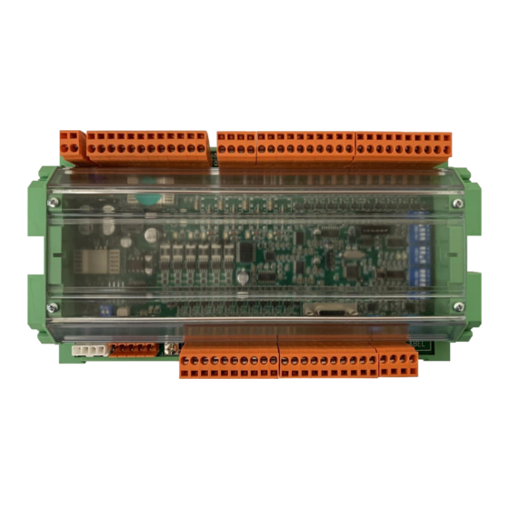
- Page 6 CEBORA S.p.A. Interfaccia di comunicazione Dati tecnici convertitori DC/DC L’interfaccia di comunicazione è costituita da una monoscheda, assemblata su modulo a profilo ingresso tensione PHOENIX, l’installazione alimentazione 24 Vdc (±15%) / 0,5A nell’armadio del Controllo Robot. costruzione secondo La monoscheda è suddivisa nelle seguenti standard 73/23/CEE;...
- Page 7 CEBORA S.p.A DIP2-DIP3-DIP4 – Opzioni di configurazione Connettori J1 – Alimentazione Segnale +24Vdc J6 – CAN bus riservato per altre applicazioni Segnale +VCAN (nc) -VCAN CAN low DIP2 Pos. Opzioni CAN high AN_IN0 disabilitato AN_IN0 abilitato J9 – CAN bus lato Generatore...
- Page 8 CEBORA S.p.A. IMPORTANT: BEFORE STARTING THE - Do not place your body between the EQUIPMENT, READ THE CONTENTS OF electrode/torch lead and work cables. If the THIS MANUAL, WHICH MUST BE STORED electrode/torch lead cable is on your right IN A PLACE FAMILIAR TO ALL USERS FOR...
- Page 9 CEBORA S.p.A Electric shock from welding electrode or WARNING label wiring can kill. The following numbered text corresponds to the 1.1 Wear dry insulating gloves. Do not touch label numbered boxes. electrode with bare hand. Do not wear wet or damaged gloves.
-
Page 10: System Description
CEBORA S.p.A. SYSTEM DESCRIPTION Composition The Cebora ROBOT Welding System is a It is made up of a Power Source, eventually equipments system developed for use in equipped with a Cooling Unit, a Wire Feeder, a combination with a Welding Robot arm on Control Panel and a Robot Interface (fig. - Page 11 Interface. RAI448 architecture The interface RAI448 is connected to the Power The interface is based on Cebora PLC with CAN Source CAN bus connector via the signal cable bus connection for Power Source side and (3) (not supplied with the Robot Interface).
- Page 12 CEBORA S.p.A. Communication interface DC/DC converters technical data The communication interface is made up of a power supply input voltage 24 Vdc (±15%) / 0,5A single board, assembled on PHOENIX UM 108- PROFIL module for the Robot Control cabinet construction inside installation.
- Page 13 CEBORA S.p.A DIP2-DIP3-DIP4 – Option configuration Connectors J1 – Power Supply Signal +24Vdc J6 – CAN bus reserved for further appliances Signal +VCAN (nc) -VCAN DIP2 Pos. Option CAN low AN_IN0 disabled CAN high AN_IN0 enabled AN_IN1 disabled J9 – CAN bus Power Source side...
- Page 14 CEBORA S.p.A. IMPORTANTE: ANTES DE LA PUESTA EN - Colocar el cable de masa y de la pinza FUNCIONAMIENTO DEL APARATO, LEER portaelectrodo o de la antorcha de manera que EL CONTENIDO DE ESTE MANUAL Y permanezcan flanqueados. Si posible, fijarlos...
- Page 15 CEBORA S.p.A EN CASO DE MAL FUNCIONAMIENTO 1.1 Llevar guantes aislantes. No tocar el PEDIR LA ASISTENCIA DE PERSONAL electrodo con las manos desnudas. CUALIFICADO llevar guantes mojados o dañados. 1.2 Asegurarse de estar aislados de la pieza a Placa de las ADVERTENCIAS soldar y del suelo.
-
Page 16: Descripción Del Sistema
DESCRIPCIÓN DEL SISTEMA Composición Está compuesto por un Generador, equipado El Sistema de Soldadura ROBOT Cebora es un sistema de equipos realizado para ser acoplado a eventualmente con un Grupo de Enfriamiento, un un brazo Robot Soldante, en instalaciones de Carro Arrastrahilo, un Panel de Control y una soldadura automatizadas. - Page 17 La Interfaz Analogica Robot RAI448 es una El cable CAN bus (4), largo 1,5 m, está interfaz de conexión entre Generadores MIG o TIG Cebora y Robots Industriales Soldadores que preasemblado con un conector hembra de panel, tienen unidades de control carentes de líneas de de 7 polos, que se utilizará...
- Page 18 CEBORA S.p.A. Interfaz de comunicaciόn Datos tecnicos convertidores DC/DC. La interfaz de communicaciόn se forma de una monotarjeta, montada en el módulo a perfil UM entrada tension alimentacion 24 Vdc (±15%) / 0,5A 108 PHOENIX, para la instalación en el armario del Control Robot.
- Page 19 CEBORA S.p.A DIP2-DIP3-DIP4 – Configuracion opciones Conectores J1 – Alimentaciόn Señal +24Vdc J6 – CAN bus reservado para otra aplicaciones Señal +VCAN (nc) -VCAN DIP2 Pos. Opciones CAN low AN_IN0 deshabilitado CAN high AN_IN0 habilitado AN_IN1 deshabilitado J9 – CAN bus lado Generador AN_IN1 habilitado Señal...
- Page 20 CEBORA S.p.A. Esempio di collegamento. In funzione delle esigenze dell’applicazione Robot, può essere non necessario utilizzare tutti i segnali di ingresso e uscita disponibili sull’Interfaccia Robot. Alcuni segnali sono condizionati dalla posizione dei DIP Switches (vedi par. 3.7). Connection example.
- Page 21 CEBORA S.p.A. Mappatura segnali. Signals mapping. Mapeo señales. RAI448 Note TIG / PW Note DIG_IN0 weld_start Active high weld_start Active high DIG_IN1 robot_ready Active high robot_ready Active high DIG_IN2 op_mode_0 Active high op_mode_0 Active high DIG_IN3 op_mode_1 Active high op_mode_1...
- Page 22 CEBORA S.p.A. Dati tecnici ingressi e uscite. Inputs and outputs technical data. Datos tecnicos entradas y salidas. Digital inputs (connectors J7, J8, J10, J11). Analog voltage output (connector J5). input current 5 mA, min.; output voltage range 0 ÷ 10 Vdc;...
- Page 23 The interface programming is possible by connecting the PC to the programming connector of the RAI448. In the Cebora web site are available the program file, named *.fwu, to install in the equipment and the Instruction Manual to help in using Cebora Device Manager.
- Page 24 CEBORA S.p.A. Via Andrea Costa n° 24 – 40057 Cadriano di Granarolo – Bologna – Italy CEBORA S.p.A. Tel. +39 051765000 – Telefax: +39 051765222 http://www.cebora.it – E-Mail: cebora@cebora.it 3301070/C 19/09/2022...
Need help?
Do you have a question about the 448.00 and is the answer not in the manual?
Questions and answers