Advertisement
Available languages
Available languages
Quick Links
MANUALE DI ISTRUZIONI PER INTERFACCIA DIGITALE
I
ROBOT, Art. 210.20, PER INSTALLAZIONI MIG E TIG ROBOT.
INSTRUCTIONS MANUAL FOR ROBOT DIGITAL INTERFACE,
GB
Art. 210.20, FOR MIG AND TIG ROBOT INSTALLATIONS.
MANUAL DE ISTRUCCIONES PARA INTERFAZ DIGITAL
E
ROBOT, Art. 210.20, PARA INSTALLACCIONES MIG Y TIG
ROBOT.
3.300.185-D
pag. 2
page 13
pag. 24
02-10-2013
Advertisement

Related Manuals for Cebora 210.20


Summary of Contents for Cebora 210.20
- Page 1 MANUALE DI ISTRUZIONI PER INTERFACCIA DIGITALE pag. 2 ROBOT, Art. 210.20, PER INSTALLAZIONI MIG E TIG ROBOT. INSTRUCTIONS MANUAL FOR ROBOT DIGITAL INTERFACE, page 13 Art. 210.20, FOR MIG AND TIG ROBOT INSTALLATIONS. MANUAL DE ISTRUCCIONES PARA INTERFAZ DIGITAL ROBOT, Art. 210.20, PARA INSTALLACCIONES MIG Y TIG pag.
- Page 2 IMPORTANTE: PRIMA DELLA MESSA IN - Non avvolgere i cavi di massa e della pinza OPERA DELL'APPARECCHIO LEGGERE IL porta elettrodo o della torcia attorno al corpo. CONTENUTO DI QUESTO MANUALE E - Non stare mai tra il cavo di massa e quello della CONSERVARLO, PER TUTTA LA VITA pinza portaelettrodo o della torcia.
- Page 3 Targa delle AVVERTENZE. Il testo numerato seguente corrisponde alle caselle 1.1 Indossare guanti isolanti. toccare numerate della targa. l’elettrodo a mani nude. Non indossare guanti umidi o danneggiati. 1.2 Assicurarsi di essere isolati dal pezzo da saldare e dal suolo. 1.3 Scollegare la spina del cavo di alimentazione prima di lavorare sulla macchina.
- Page 4 DESCRIZIONE SISTEMA. Composizione. È composto generalmente da un Generatore, Il Sistema di Saldatura ROBOT Cebora è un equipaggiato eventualmente Gruppo sistema di apparecchiature idoneo alla saldatura Raffreddamento, da un Carrello Trainafilo, da un realizzato per essere abbinato ad un braccio Robot Pannello di Controllo e da una Interfaccia Robot Saldante, su impianti di saldatura automatizzati.
- Page 5 Concetto dell’apparecchiatura. L’Interfaccia Digitale Robot RDI210, art. 210.20, è Il cavo Profibus (26), lungo 2 m, è un cavo a 4 fili un’interfaccia di collegamento fra Generatore più schermo, preassemblato con due connettori Cebora e Robot Industriali Saldanti, basata su Bus Sub-D a 9 poli maschio.
- Page 6 Dati tecnici. 3.3.1 Alimentazione Terminal Bus di campo Profibus DP. Controller. Profibus Baud rate fino a 12 Mbps, selezione Terminal Controller richiede automatica. un’alimentazione a 24 V Numero di moduli Questa tensione alimenta sia la parte elettronica del sul K-bus 0 ÷...
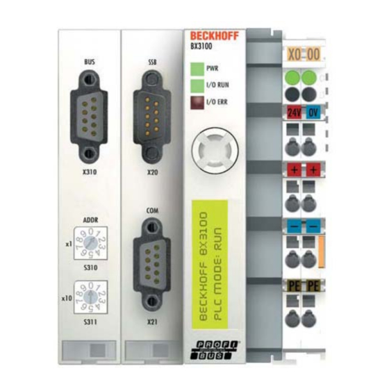
- Page 7 La linguetta in plastica (di colore arancio in fig. Interfaccia Profibus. 3.1) e le guide della scanalatura in alto e in basso Tipologia rete bus lineare con terminatori di nel Bus Terminal Controller e nei Moduli I/O bus attivi su entrambi i capi. aggiuntivi, garantiscono che i contatti a lamelle Mezzo cavo schermato a due coppie di...
- Page 8 Siccome il Bus Terminal Controller BX3100 3.8.2 Led di diagnostica (Diag Leds). provvede anche all’isolamento galvanico del I led di diagnostica sono collegamento del bus, in alcuni casi può essere suddivisi come segue: possibile non effettuare il collegamento dello Bus: diagnosi del bus di schermo.
- Page 9 3.8.5 Led diagnosi del K-bus. Errori del firmware sono indicati nel display via Led I/O Descrizione “FW-Error” ed il numero di errore. Nessun dato è scambiato via K-bus. Display Descrizione Rosso Errore. Il tipo di errore è lamp. indicato nel display. FW-Error Contattare servizio...
- Page 10 Errore nel K-bus, nel registro di comunicazione Sostituire il Modulo I/O n. con il Modulo I/O n. Errore all’inizializzazione. Sostituite il Bus Terminal Controller. Eseguire il reset hardware del Bus Terminal Controller Errore nei dati interni. (spegnere e riaccendere). Rotary switches cambiati Eseguire il reset hardware del Bus Terminal Controller dopo un reset software.
- Page 11 Data in Process Image fra Controllo Segnali fra Moduli I/O e Generatore. Robot e Generatore. L’interfaccia RDI210, art. 210.20 prevede anche la La configurazione dei messaggi dei bus di campo possibilità di scambiare segnali di ingresso / uscita (Data Process Image) adottati negli impianti di tra Generatore e Moduli I/O aggiuntivi.
- Page 12 Hardware del Bus Terminal. Led di diagnostica Codice Indicazione sul Errore 2134 9010 display del BX3100 K-bus CEBORA GATEWAY Verde fisso Verde fisso Rosso lamp. REL. X.4 Verde lamp. Rosso lamp. DEFAULT - CONFIG CEBORA GATEWAY Verde fisso Verde fisso Rosso lamp.
- Page 13 − IMPORTANT: BEFORE STARTING place your body between EQUIPMENT, READ THE CONTENTS OF electrode/torch lead and work cables. If the THIS MANUAL, WHICH MUST BE STORED electrode/torch lead cable is on your right side, IN A PLACE FAMILIAR TO ALL USERS FOR the work cable should also be on your right THE ENTIRE OPERATIVE LIFE-SPAN OF THE side.
- Page 14 WARNING label. Electric shock from welding electrode or wiring can kill. The following numbered text corresponds to the 1.1 Wear dry insulating gloves. Do not touch label numbered boxes. electrode with bare hand. Do not wear wet or damaged gloves. 1.2 Protect yourself from electric shock by insulating yourself from work and ground.
-
Page 15: System Description
SYSTEM DESCRIPTION. Composition. The Cebora ROBOT Welding System is a It is made up of a Power Source, which may be equipments system suitable for welding, developed equipped with a Cooling Unit, a Wire Feeder, a for use in combination with a Welding Robot arm Control Panel and a Robot Interface (fig. - Page 16 Machine concept. The Robot Digital Interface RDI210, art 210.20, is Profibus cable (26), 2 m long, is a 4 wires plus a connection interface between Cebora Power shield cable, preassembled with two Sub-D 9 poles Source and Industrial Welding Robot, based on the male connectors.
- Page 17 Technical data. 3.3.1 Terminal Controller power Field bus Profibus-DP. supply. Profibus Baud rate Mbps, The Bus Terminal Controller requires a 24 V automatically selected. This supply voltage feeds both the BX3100 Number of modules module electronic parts and added I/O Modules, on K-bus 0 ÷...
- Page 18 The plastic tongue (orange colour in fig. 3.1) and Profibus Interface. groove guides on the top and bottom of the Bus Network topology linear bus, with active bus Terminal Controller and of the added I/O Modules terminators at both ends. guarantees that the power contacts mate securely.
- Page 19 Since the Bus Terminal Controller BX3100 also 3.8.2 Diagnostic leds (Diag Leds). provides to the galvanic isolation of the bus The diagnostic leds are sub connection, in appropriate cases may be possible divided as follows: not to carry out the connection of the screen. Bus: field (Profibus) diagnosis.
- Page 20 3.8.5 Led for K-bus diagnosis. Firmware errors are shown in the display via “FW- Led I/O Description Error” and the error number. No data is exchanged via the K-bus. Display Description Error. The type is indicated flashing in the display. FW-Error Please contact support.
- Page 21 K-bus error in register communication with I/O Exchange the nth I/O Module. Module n. Error at initialization. Replace Bus Terminal Controller. Perform a hardware reset on the Bus Terminal Internal data error. Controller (switch off and on again). Rotary switches changed Perform a hardware reset on the Bus Terminal after a software reset.
- Page 22 Data Process Image between Robot Signals between I/O Modules and Power Control and Power Source. Source. The field bus messages configuration (Data The RDI210 Interface, art. 210.20 preview also the Process Image) used in the Cebora automated possibility exchange input/output...
- Page 23 The example illustrates the System behaviour, with Data Process Image version X.4, in relation to the different possible Hardware configurations of the Bus Terminal. Diagnostic leds K-bus BX3100 display Error 2134 9010 indication Code CEBORA GATEWAY Green fix Green fix REL. X.4 flashing Green DEFAULT - CONFIG flashing. flashing CEBORA GATEWAY...
- Page 24 IMPORTANTE: ANTES DE LA PUESTA EN - Colocar el cable de masa y de la pinza FUNCIONAMIENTO DEL APARATO, LEER portaelectrodo o de la antorcha de manera que EL CONTENIDO DE ESTE MANUAL Y permanezcan flanqueados. Si posible, fijarlos CONSERVARLO, DURANTE TODA LA VIDA junto con cinta adhesiva.
- Page 25 EN CASO DE MAL FUNCIONAMIENTO 1.1 Llevar guantes aislantes. No tocar el electrodo PEDIR LA ASISTENCIA DE PERSONAL con las manos desnudas. No llevar guantes CUALIFICADO mojados o dañados. 1.2 Asegurarse de estar aislados de la pieza a Placa de las ADVERTENCIAS. soldar y del suelo.
-
Page 26: Descripción Del Sistema
DESCRIPCIÓN DEL SISTEMA. Composición. El Sistema de Soldadura ROBOT Cebora es un Está compuesto por un Generador, equipado sistema de equipos idóneo para la soldadura, eventualmente con un Grupo de Enfriamiento, un realizado para ser acoplado a un brazo Robot... - Page 27 Concepto del dispositivo. La Interfaz Digital Robot RDI210, art. 210.20, es El cable Profibus (26), largo 2 m, es un cable de 4 una interfaz de conexión entre Generador Cebora y hilos más pantalla, pre ensamblado con dos Robot Industriales Soldante, basada en el Bus conectores Sub-D 9 polos machos.
- Page 28 Datos técnicos. 3.3.1 Alimentación Terminal Bus de campo Profibus-DP. Controller. Profibus baud rate hasta 12 Mbps, selección Terminal Controller requiere automática. alimentación de 24 V Número de módulos Esta tensión alimenta tanto la parte electrónica del en el K-bus 0 ÷ 64. módulo BX3100 como...
- Page 29 Interfaz Profibus. La lengüeta en plástico (de color naranja en Tipología de red bus linear con terminadores de fig. 3.1) y las guías de la ranura por encima y por bus activos en ambos cabos. debajo del Bus Terminal Controller y de los Medio cable blindado con dos pares de Módulos I/O adicionales, garantizan que los...
- Page 30 En el Bus Terminal Controller BX3100, el cuerpo 3.8.2 Led para el diagnóstico (Diag Leds). del conector es acoplado con una baja resistencia a Los led de diagnóstico están guía DIN de montaje del módulo mismo. subdivididos como sigue: Ya que el Bus Terminal Controller BX3100 Bus: diagnosis del bus de proporciona también el aislamiento galvánico de la campo (Profibus).
- Page 31 3.8.5 Led para diagnóstico del K-bus. Los errores de firmware son visualizados en el Led I/O Descripción display mediante “FW-Error” y el número de error. Ningún dato sido intercambiado vía K-bus. Display Descripción Rojo El tipo de error es indicado centelleante en el display.
- Page 32 Error en el K-bus en el registro de comunicación Intercambiar el Módulo I/O n. con el Módulo I/O n. Error en la inicialización. Sustituir el Bus Terminal Controller. Efectuar el reset hardware del Bus Terminal Controller Error en los datos internos. (apagar y volver a encender).
- Page 33 Data Process Image entre Control Robot Señales entre Módulos I/O y Generador. y Generador. La Interfaz RDI210, art. 210.20 prevé también la La configuración de los mensajes de los bus de posibilidad intercambiar señales campo (Data Process Image) adoptados en los entradas/salidas entre Generador y Módulos I/O...
- Page 34 El ejemplo ilustra el comportamiento del Sistema, con Data Process Image en versión X.4, en relación de las posible configuraciones Hardware del Bus Terminal. Led Diagnostico Código Indicación en el Error 2134 9010 display del BX3100 K-bus Rojo CEBORA GATEWAY Verde fijo Verde fijo REL. X.4 centelleante Verde Rojo DEFAULT - CONFIG centelleante centelleante Rojo...
- Page 35 CEBORA S.p.A. Via Andrea Costa n° 24 – 40057 Cadriano di Granarolo – Bologna – Italy Tel. +39 051765000 – Telefax: +39 051765222 http://www.cebora.it – E-Mail: cebora@cebora.it 3.300.185-D...
- Page 36 CEBORA S.p.A. Via Andrea Costa n° 24 – 40057 Cadriano di Granarolo – Bologna – Italy Tel. +39 051765000 – Telefax: +39 051765222 http://www.cebora.it – E-Mail: cebora@cebora.it 3.300.185-D...
Need help?
Do you have a question about the 210.20 and is the answer not in the manual?
Questions and answers