Advertisement
Available languages
Available languages
Quick Links
MANUALE DI ISTRUZIONI PER INTERFACCIA DIGITALE
I
ROBOT, Art. 210.00, PER INSTALLAZIONI MIG E TIG ROBOT.
INSTRUCTIONS MANUAL FOR ROBOT DIGITAL INTERFACE,
GB
Art. 210.00, FOR MIG AND TIG ROBOT INSTALLATIONS.
MANUAL DE ISTRUCCIONES PARA INTERFAZ DIGITAL
E
ROBOT, Art. 210.00, PARA INSTALLACCIONES MIG Y TIG
ROBOT.
BETRIEBSANLEITUNG
D
ROBOTERSCHNITTSTELLE, Art. 210.00, FÜR INSTALLATIONEN
MIG UND TIG ROBOT.
3.300.987-H
FÜR
DIE
pag. 2
page 13
pag. 24
DIGITALE
seite 36
26-09-2013
Advertisement

Related Manuals for Cebora 210.00


Summary of Contents for Cebora 210.00
- Page 1 MANUALE DI ISTRUZIONI PER INTERFACCIA DIGITALE pag. 2 ROBOT, Art. 210.00, PER INSTALLAZIONI MIG E TIG ROBOT. INSTRUCTIONS MANUAL FOR ROBOT DIGITAL INTERFACE, page 13 Art. 210.00, FOR MIG AND TIG ROBOT INSTALLATIONS. MANUAL DE ISTRUCCIONES PARA INTERFAZ DIGITAL ROBOT, Art. 210.00, PARA INSTALLACCIONES MIG Y TIG pag.
- Page 2 IMPORTANTE: PRIMA DELLA MESSA IN - Non avvolgere i cavi di massa e della pinza OPERA DELL'APPARECCHIO LEGGERE IL porta elettrodo o della torcia attorno al corpo. CONTENUTO DI QUESTO MANUALE E - Non stare mai tra il cavo di massa e quello della CONSERVARLO, PER TUTTA LA VITA pinza portaelettrodo o della torcia.
- Page 3 Targa delle AVVERTENZE. Il testo numerato seguente corrisponde alle caselle 1.1 Indossare guanti isolanti. toccare numerate della targa. l’elettrodo a mani nude. Non indossare guanti umidi o danneggiati. 1.2 Assicurarsi di essere isolati dal pezzo da saldare e dal suolo. 1.3 Scollegare la spina del cavo di alimentazione prima di lavorare sulla macchina.
- Page 4 DESCRIZIONE SISTEMA. Composizione. È composto generalmente da un Generatore, Il Sistema di Saldatura ROBOT Cebora è un equipaggiato eventualmente Gruppo sistema di apparecchiature idoneo alla saldatura Raffreddamento, da un Carrello Trainafilo, da un realizzato per essere abbinato ad un braccio Robot Pannello di Controllo e da una Interfaccia Robot Saldante, su impianti di saldatura automatizzati.
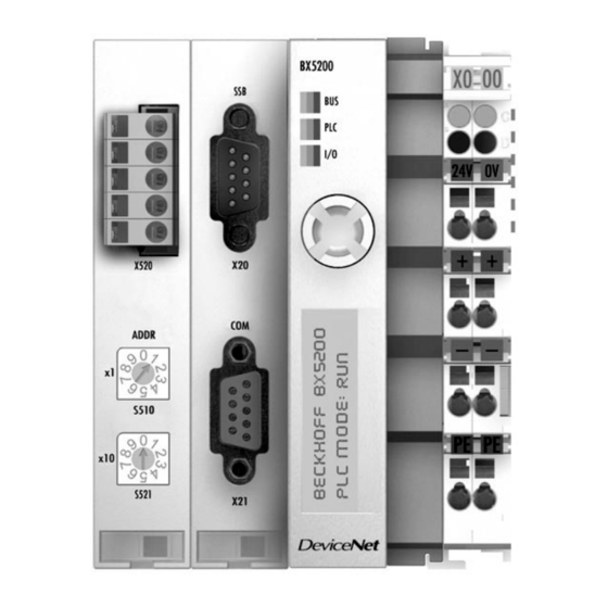
- Page 5 Concetto dell’apparecchiatura. L’Interfaccia Digitale Robot RDI210, art. 210.00, è Il cavo DeviceNet (26), lungo 2 m, è un cavo a 4 un’interfaccia di collegamento fra Generatore fili più schermo, preassemblato Cebora e Robot Industriali Saldanti, basata sul Bus morsettiere sconnettibili a 5 poli, provviste ognuna Controller BX5200 Beckhoff.
- Page 6 La connessione è realizzata tramite morsetti a Numero di molla chiamati 24 V e 0 V. Terminali sul bus 0 ÷ 63 (BX5200 per Cebora deve essere impostato a 5). Byte periferici 244 byte d’ingresso e 244 byte d’uscita.
- Page 7 La linguetta e la guida della scanalatura in alto e in Il pin 5, quello in alto nella strip, non è utilizzato. basso del Bus Terminal Controller e dei Bus Il pin 4 è relativo al segnale CAN high. Terminals garantiscono che il contatto di potenza Il pin 3 è...
- Page 8 Porta DeviceNet. Configurazione Terminal cavo DeviceNet è Controller. equipaggiato con il resistore Prima di utilizzare il Bus Controller, impostare il di terminazione da 120 ohm, numero del nodo (MAC ID). su entrambi i capi, inserito Questa impostazione è effettuata tramite i due sulla linea principale, fra i rotary switches sul Bus Controller, visibili in segnali CAN high e CAN...
- Page 9 3.8.2 Led di diagnostica (Diag Leds). 3.8.5 Led diagnosi del K-Bus. I led di diagnostica sono Led I/O Descrizione suddivisi come segue: Nessun dato è scambiato via Bus: diagnosi del bus di K-Bus. campo (DeviceNet). Rosso Lampeggiante errore – tipo PLC: diagnosi fisso errore –...
- Page 10 3.9.1 Codici Errore del K-Bus. Codice Argo- Descrizione Soluzione errore mento Controllare che la tensione di alimentazione sia esente da picchi o buchi di tensione. Problema di EMC Implementare le misure EMC. Se è presente un errore sul K-bus, può essere localizzato con il restart del controller (spegnere e riaccendere).
- Page 11 (Data Process Image) adottati negli impianti di Segnali fra Moduli I/O e Generatore. saldatura automatizzati Cebora è descritta nei L’interfaccia RDI210, art. 210.00 prevede anche la seguenti manuali, forniti a corredo dei Generatori: possibilità di scambiare segnali di ingresso / uscita −...
- Page 12 L’esempio illustra il comportamento del Sistema, con Data process image versione X.4, in relazione alle diverse possibili configurazioni Hardware del Bus Terminal. Codice Led di diagnostica Visualizzazione Errore 2134 9010 display BX5200 K-Bus CEBORA GATEWAY Verde fisso Verde fisso Rosso lamp. REL. X.4 Verde lamp. Rosso lamp. DEFAULT - CONFIG CEBORA GATEWAY Verde fisso Verde fisso Rosso lamp.
- Page 13 − IMPORTANT: BEFORE STARTING place your body between EQUIPMENT, READ THE CONTENTS OF electrode/torch lead and work cables. If the THIS MANUAL, WHICH MUST BE STORED electrode/torch lead cable is on your right side, IN A PLACE FAMILIAR TO ALL USERS FOR the work cable should also be on your right THE ENTIRE OPERATIVE LIFE-SPAN OF THE side.
- Page 14 WARNING label. Electric shock from welding electrode or wiring can kill. The following numbered text corresponds to the 1.1 Wear dry insulating gloves. Do not touch label numbered boxes. electrode with bare hand. Do not wear wet or damaged gloves. 1.2 Protect yourself from electric shock by insulating yourself from work and ground.
-
Page 15: System Description
SYSTEM DESCRIPTION. Composition. The Cebora ROBOT Welding System is a It is made up of a Power Source, which may be equipments system suitable for welding, developed equipped with a Cooling Unit, a Wire Feeder, a for use in combination with a Welding Robot arm Control Panel and a Robot Interface (fig. - Page 16 Machine concept. The Robot Digital Interface RDI210, art 210.00, is DeviceNet cable (26) is 2 m long, is a 4 wires plus a connection interface between Cebora Power shield cable, preassembled with two 5 poles Sources and Industrial Welding Robot, based on terminals board connectors, provided with 120 the Bus Controller BX5200 Beckhoff.
- Page 17 Number of The connection is made by means of the upper bus terminals 0 ÷ 63 (Cebora BX5200 spring loaded terminals labelled 24 V and 0 V. must be set to 5). Periphery byte 244 input byte and 244 output byte.
- Page 18 By attaching a Bus Terminal the blade contacts on Pin 5 is the connection strip's top most pin and is the left hand side of the Bus Terminal are not used. connected to the spring contacts. Pin 4 is related to the CAN high signal. The tongue and groove guides on the top and Pin 3 is related to the screen and is internally bottom of the Bus Terminal Controller and of the...
- Page 19 DeviceNet Port. Bus Terminal Controller configuration. DeviceNet cable Before you start using the Bus Controller, you Ω equipped with a 120 must set the node number (MAC ID). terminating resistors, on both These settings are made with the 2 rotary switches ends, on the main line, on the Bus Controller, shown in figure a side.
- Page 20 3.8.2 Diagnostic leds (Diag Leds). 3.8.5 Led for K-Bus diagnosis. The diagnostic leds are sub Led IO Description divided as follows: No data are exchange via the Bus: field bus (DeviceNet) K-Bus. diagnosis. Error flashing – error type – Red fixed PLC: PLC (BX5200) display.
- Page 21 3.9.1 Error code for K-Bus diagnosis. Error Argument Description Solution Code. Check power supply for over voltage or under voltage peaks. Implement EMC measures. EMC problem If a K-Bus error is present, it can be localized by a restart of the controller (by switching it off and then on again).
- Page 22 In these manuals all signals exchanged between the between added I/O Modules and Power Source. Cebora Welding System and the Robot Control are Such signals do not influence on the Data Process listed and described. Image definition. The first 128 inputs and first 96 outputs of the Data...
- Page 23 The example illustrates the System behaviour, with Data process image version X,4, in relation to the different possible Hardware configurations of the Bus Terminal. K-Bus Diagnostic leds BX5200 display Error 2134 9010 indication Code CEBORA GATEWAY Green fix Green fix flashing REL. X.4 Green DEFAULT - CONFIG flashing. flashing CEBORA GATEWAY...
- Page 24 IMPORTANTE: ANTES DE LA PUESTA EN - Colocar el cable de masa y de la pinza FUNCIONAMIENTO DEL APARATO, LEER portaelectrodo o de la antorcha de manera que EL CONTENIDO DE ESTE MANUAL Y permanezcan flanqueados. Si posible, fijarlos CONSERVARLO, DURANTE TODA LA VIDA junto con cinta adhesiva.
- Page 25 EN CASO DE MAL FUNCIONAMIENTO 1.1 Llevar guantes aislantes. No tocar el electrodo PEDIR LA ASISTENCIA DE PERSONAL con las manos desnudas. No llevar guantes CUALIFICADO mojados o dañados. 1.2 Asegurarse de estar aislados de la pieza a Placa de las ADVERTENCIAS. soldar y del suelo.
-
Page 26: Descripción Del Sistema
DESCRIPCIÓN DEL SISTEMA. Composición. El Sistema de Soldadura ROBOT Cebora es un Está compuesto por un Generador, equipado sistema de equipos idóneo para la soldadura, eventualmente con un Grupo de Enfriamiento, un realizado para ser acoplado a un brazo Robot... - Page 27 Concepto del dispositivo. La Interfaz Digital Robot RDI210, art. 210.00, es El cable DeviceNet (26), largo 2 m, es un cable de una interfaz de conexión entre Generador Cebora y 4 hilos más pantalla, preassemblato con dos Robot Industriales Soldante, basada en el Bus tableros de bornes desconectables de 5 polos, cada Controller BX5200 Beckoff.
- Page 28 La conexión está realizada mediante bornes de potencia). muelle llamados 24 V y 0 V. Número de terminales en el bus 0 ÷ 63 (BX5200 para Cebora tiene programado a 5). Bytes periféricos 244 bytes de entrada y 244 bytes de salida.
- Page 29 Conectando un Bus Terminal, los contactos a El pin 5, el alto en la strip, no se ha utilizado. lámina en el lado izquierdo del Bus Terminal El pin 4 corresponde a la señal CAN high. vienen conectados a los contactos a muelle. El pin 3 corresponde a la pantalla y está...
- Page 30 Configuración del Bus Terminal Puerta DeviceNet. Controller. cable DeviceNet está Antes de utilizar el Bus Controller, programar el dotado resistor número del nudo (MAC ID). terminación de 120 ohm, en Esta programación se hace mediante los dos rotary ambos cabos, insertado en la switches en el Bus Controller, visibles en la figura.
- Page 31 3.8.2 Led para el diagnóstico (Diag Leds). 3.8.5 Led diagnosis del K-Bus. Los led de diagnóstico están Led I/O Descripción subdivididos como sigue: Ningún dato sido Bus: diagnosis del bus de intercambiado vía K-Bus. campo (DeviceNet). Centelleante error – tipo de Rojo fijo PLC: diagnosis error –...
- Page 32 3.9.1 Códigos de error del K-Bus. Código Tema Descripción Solución error Controlar que la tensión de alimentación no tenga picos o agujeros de tensión. Implementar las medidas EMC. Problema de EMC Si hay un error en el K-bus, se podrá localizar con el restart del Controller (apagar y volver a encender).
- Page 33 Bus Terminal Controller BX5200 individual, sin ningún Módulo I/O adicional y se refieren Señales entre Módulos I/O y Generador. exclusivamente señales DeviceNet La Interfaz RDI210, art. 210.00 prevé también la intercambiadas entre Control Robot y Generador. posibilidad intercambiar señales entradas/salidas entre Generador y Módulos I/O NOTA: Al instalar Módulos I/O adicionales la...
- Page 34 K-Bus y la configuración que requerir el correspondiente archivo Hardware puede también ser diferente de la .BIN a la Oficina Técnica Cebora. configuración Software. El archivo .BIN insertado en la memoria Si en lugar de otro el terminador está insertado en del BX5200 debe ser compatible con la el K-bus, sin Módulos I/O adicionales en el K-bus,...
- Page 35 El ejemplo ilustra el comportamiento del Sistema, con la Data Process Image en la versión X.4, en relación de las posible configuraciones del Hardware del Terminal de Bus. Código Led Diagnostico Indicación en el Error 2134 9010 display del BX5200 Rojo CEBORA GATEWAY Verde fijo Verde fijo centelleante REL. 2.4 Verde Rojo DEFAULT - CONFIG centelleante centelleante...
- Page 36 WICHTIG: VOR DER INBETRIEBNAHME Um die Risiken durch die Aussetzung an elektro- GERÄTS INHALT magnetische Felder zu mindern, müssen sich alle VORLIEGENDEN BETRIEBSANLEITUNG Schweißerinnen folgenden AUFMERKSAM DURCHLESEN; Verfahrensweisen halten: BETRIEBSANLEITUNG MUSS FÜR - Sicherstellen, daß das Massekabel und das GESAMTE LEBENSDAUER DES GERÄTS AN Kabel der Elektrodenzange oder des Brenners EINEM ALLEN INTERESSIERTEN PERSONEN nebeneinan der bleiben.
- Page 37 Als Eigentümer der Geräte müssen Sie sich bei Von der Schweißelektrode oder vom Kabel unserem örtlichen Vertreter über die zugelassenen verursachte Stromschläge können tödlich sein. Sammlungssysteme informieren. Die Umsetzung Für einen angemessenen Schutz gegen genannter Europäischer Richtlinie wird Umwelt Stromschläge Sorge tragen. und menschlicher Gesundheit zugute kommen! 1.1 Isolierhandschuhe tragen.
-
Page 38: Beschreibung Des Systems
BESCHREIBUNG DES SYSTEMS. Aufbau. Das Schweißsystem ROBOT Cebora ist für den Es umfaßt im Allgemeinen eine Stromquelle sowie Betrieb Verbindung einem ggf. ein Kühlaggregat, ein Drahtvorschubgerät, Schweißroboterarm einer automatischen eine Steuertafel und eine Roboterschnittstelle Schweißanlage konzipiert. (siehe Abb. 2.1). Abb. 2.1 Verbindungskabel Stromquelle/Steuertafel. - Page 39 Konzept des Geräts. Die digitale Roboterschnittstelle RDI210, art. Das DeviceNet-Kabel (26) von 2 m Länge ist ein 210.00 ist eine Schnittstelle für die Verbindung 4-adriges Kabel mit Schirm, das mit zwei 5- zwischen der Stromquelle von Cebora und poligen Steckklemmleisten versehen ist, die industriellen Schweißrobotern, die auf dem Bus-...
- Page 40 Feldebene elektrisch isoliert. Leistungskontakte). Der Anschluß erfolgt mit den Federkraftklemmen Anzahl Klemmen mit der Bezeichnung "24 V" und "0 V". am Bus 0 - 63 (BX5200 für Cebora muß auf 5 eingestellt sein). Peripheriebytes 244 Eingangsbytes und 244 Ausgangsbytes. Konfiguration der Schnittstelle vor Ort für KS2000.
- Page 41 Die Federkontakte sind in den Schlitzen verborgen, Pin 5 ist dabei der oberste Pin auf der Stecker um den Berührungsschutz sicherzustellen. leiste, der nicht benutzt wird. Durch das Anreihen einer Busklemme werden die Pin 4 ist für das CAN-High-Signal bestimmt. Messerkontakte linken Seite...
- Page 42 DeviceNet-Anschluß. Um das Anschließen und/oder Lösen des Bus- Das DeviceNet-Kabel verfügt Controllers im laufenden Betrieb zu ermöglichen, über einen Abschluß ist es wichtig, daß der Abschluß widerstand fest widerstand von 120 Ohm an Kabel angeschlossenen beiden Enden, der auf der Steckverbinder verbunden ist.
- Page 43 3.8.2 Diagnose-LEDs (Diag Leds). 3.8.5 LEDs für die Diagnose des K-Busses. Die Diagnose-LEDs sind wie LED I/O Beschreibung folgt aufgeteilt: Kein Datenaustausch über Bus: Diagnose den K-Bus. Feldbusses (DeviceNet). Leuchtet Blinkend Fehler – Fehlerart PLC: Diagnose – Display. (BX5200). Leuchtet Online-Zugriff auf Register I/O: K-Bus-Diagnose.
- Page 44 3.9.1 Fehlercodes des K-Busses. Fehler Argu- Beschreibung Abhilfe -code ment Die Spannungsversorgung auf Überspannungsspitzen Spannungseinbrüche kontrollieren. EMV- EMV-Problem Maßnahmen ergreifen. Liegt beim K-Bus ein Fehler vor, kann durch erneutes Starten (aus- und wieder einschalten) der Fehler lokalisiert werden. Fabrikeinstellung Hilfe EEPROM-Prüfsummenfehler.
- Page 45 EINGANGSPROZESSABBILDS. Aufbau. Eingangsprozessabbild zwischen Das Eingangsprozessabbild definiert die Eingangs- Robotersteuerung und E/A-Modulen. und Ausgangssignale, die auf dem Feld bus Die Schnittstelle RDI210, art. 210.00, bietet die DeviceNet zwischen Robotersteuerung Möglichkeit der Erweiterung mit zusätzlichen E/A- (Master-Modul) und dem Busklemmen-Controller Modulen, die an den K-Bus angeschlossen werden BX5200 (Slave-Modul) ausgetauscht werden.
- Page 46 Kontrolle der entsprechende BIN-Datei Entsprechung zwischen der Konfiguration der Technischen Abteilung Cebora Software und der Konfiguration der Hardware. anfordern. Die Konfiguration der Software muß also der Die BIN-Datei im Speicher des BX5200 Hardware-Konfiguration, d.h. den auf den K-Bus muß...
- Page 47 Das Beispiel illustriert das Verhalten des Systems mit Eingangsprozessabbild Version X.4 in Bezug auf die verschiedenen möglichen Hardware-Konfigurationen der Busklemme. Fehlercode Diagnose-LEDs Anzeige auf dem des K- 2134 9010 Display BX5200 Busses Leuchtet Leuchtet CEBORA GATEWAY NEIN NEIN Blinkt rot REL. 2.4 grün grün NEIN Blinkt grün Blinkt rot DEFAULT - CONFIG Leuchtet...
- Page 48 CEBORA S.p.A. Via Andrea Costa n° 24 – 40057 Cadriano di Granarolo – Bologna – Italy Tel. +39 051765000 – Telefax: +39 051765222 http://www.cebora.it – E-Mail: cebora@cebora.it 3.300.987-H...
Need help?
Do you have a question about the 210.00 and is the answer not in the manual?
Questions and answers