Table of Contents
Advertisement
Quick Links
Advertisement
Table of Contents

Related Manuals for Dover Midland A-730 Series


Summary of Contents for Dover Midland A-730 Series
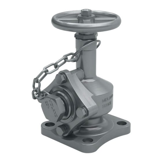
- Page 1 Part Nu mber: A-730/A-734, Rev. 1.2 Issue Date: April 25, 2024 Supersedes: A-730/A-734, Rev. 1.1 Top-Transfer 3" Angle Valve A-730 & A-734 Series Installation, Operation and Maintenance (IOM) Manual 7733 Gross Point Road • Skokie, IL 60077 • (847) 677-0333 • Fax (847) 677-0138 • www.midlandmfg.com...
-
Page 2: Table Of Contents
P/N: A-730/A-734, Rev. 1.2 Page 2 of 26 Table of Contents Introduction .......................... 3 Technical Specifications ....................3 Valve Components ......................4 Pre-Installation Regulations/Requirements ..............5 Valve Installation ........................7 Preliminary Considerations ....................7 Installation Procedure ...................... 7 Operating Procedure ......................9 Opening the Valve ...................... -
Page 3: Introduction
P/N: A-730/A-734, Rev. 1.2 Page 3 of 26 1.0 Introduction Tank cars equipped with the Midland A-730/A-734 series Top-Transfer Angle Valves offer long-term reliability and ease of maintenance leading to more efficient operations. Applications include: Liquefied Petroleum Gas (LPG) applications •... -
Page 4: Valve Components
P/N: A-730/A-734, Rev. 1.2 Page 4 of 26 Valve Components Item Qty. Part Name Handwheel Stem Retainer Assembly Body Spring Retainer Cover Outlet Flange Packing Screw w/Insert Packing Washer Top Packing Washer Bottom Seat Seal Packing Stem Seal O-Ring Outlet Handwheel Nut Bolt Lock Washer... -
Page 5: Pre-Installation Regulations/Requirements
P/N: A-730/A-734, Rev. 1.2 Page 5 of 26 Pre-Installation Regulations/Requirements 1.3.1 Regulations Midland Angle Valves are used in a variety of tank cars, many of which carry hazardous materials. The acceptance and transportation of the products is regulated by the DOT and AAR in the U.S.A., and by Transport Canada in Canada, as well as other governmental bodies, particularly when used in stationary applications. - Page 6 P/N: A-730/A-734, Rev. 1.2 Page 6 of 26 1.3.4 Required Tools Before arriving at the installation site, obtain the required tools and supplies prior to performing the procedures indicated in this guide. Recommended Wrenches Size Component Item # 7/16” Socket Stem Retainer 3/4”...
-
Page 7: Valve Installation
P/N: A-730/A-734, Rev. 1.2 Page 7 of 26 2.0 Valve Installation Preliminary Considerations 2.1.1 Prior to installation, ensure that the valve remains clean and the gasket-sealing surfaces are not damaged. Installation Procedure Be sure the car is empty and clean, and that the work area is free CAUTION: of hazardous chemicals that may have been in the car, before removing a valve or installing a new one. - Page 8 P/N: A-730/A-734, Rev. 1.2 Page 8 of 26 2.2.11 After the nuts have been tightened down on the cover plate, the valve should be “closed.” To seal the valve it is only necessary to torque the valve handwheel approximately 20 to 30 ft-lb. Under no circumstances should a “cheater”...
-
Page 9: Operating Procedure
P/N: A-730/A-734, Rev. 1.2 Page 9 of 26 3.0 Operating Procedure Opening the Valve NOTICE: Operation of the valve must conform with all applicable CTC, AAR, DOT specifications (Parts 173.31, 174.67, etc.), other governmental bodies and the operating instructions of your company. NOTICE 3.1.1 Bear in mind with the Midland angle valve that it will seal completely with much less torque than a... -
Page 10: Maintenance
P/N: A-730/A-734, Rev. 1.2 Page 10 of 26 4.0 Maintenance NOTICE: It is essential to establish a periodic retesting and preventive maintenance program for pressure relief valves. The DOT and AAR have set forth a retesting interval that should be considered the maximum length of time between tests. If your company’s experience indicates that a shorter interval is advisable, a program with more frequent retesting should be implemented. -
Page 11: Valve Disassembly
P/N: A-730/A-734, Rev. 1.2 Page 11 of 26 5.0 Valve Disassembly 5.1.1 Before valve disassembly, open and close the hand wheel to run the stem (item 2) up and down to ensure that the stem is neither bent nor binding in the threaded part of the body (item 4). Bent stems must be straightened to proceed with the disassembly. - Page 12 P/N: A-730/A-734, Rev. 1.2 Page 12 of 26 5.1.4 Take off the four (4) side flange bolts and lock washers (items 15A and 15B, respectively). Figure 5-3 Remove Flange Bolts and Washers 5.1.5 Screw a threaded nipple approximately 10” long into the removable side outlet flange (item 7). Move it back and forth to loosen the flange and work it out of the valve.
- Page 13 P/N: A-730/A-734, Rev. 1.2 Page 13 of 26 5.1.6 Raise the hand wheel slightly to lift the gasket retainer (item 3). Rotate it so that the two (2) nuts (item 18) are facing out the side flange opening. Tighten down on the handwheel to keep the gasket retainer from rotating out of position.
- Page 14 P/N: A-730/A-734, Rev. 1.2 Page 14 of 26 5.1.8 Raise the stem (item 2) up in the body as far as it will go. It now is possible to take the gasket retainer out of the valve. Needle-nose pliers may be helpful in gripping the gasket retainer to extract it through the side port opening.
-
Page 15: Valve Inspection And Replacement Parts
P/N: A-730/A-734, Rev. 1.2 Page 15 of 26 6.0 Valve Inspection and Replacement Parts NOTICE: Whenever angle valves are retested, it is recommended that new O-rings ® be installed. The Teflon seat seal and packing should be replaced, if there is any question about their serviceability. - Page 16 P/N: A-730/A-734, Rev. 1.2 Page 16 of 26 6.1.4 Body. Inspect the part for corrosive degradation, particularly in the seat and the side port areas. Clean off these areas to be sure they are free of corrosion, contamination, pits, scratches, etc., that could form leak paths.
- Page 17 P/N: A-730/A-734, Rev. 1.2 Page 17 of 26 6.1.7 Packing Screw. The thread is 1½"-12 on the valve. It must be clean and sharp without nicks, scratches, pits, and other defects that would strip or gall the thread when screwed into the body. Figure 6-7 Packing Screw ®...
- Page 18 P/N: A-730/A-734, Rev. 1.2 Page 18 of 26 6.1.10 Special Inspection Considerations NOTICE: Repair work is limited to cleaning and polishing. NOTICE WARNING: Machining Not Allowed. Machining, grinding, welding or other alterations to the valve seat or stem seat is not allowed. WARNING NOTICE: Please refer to paragraph A3.11.2 of the Tank-Car Specifications and consult Appendix E for dimensions and applicable tolerances.
-
Page 19: Valve Reassembly
P/N: A-730/A-734, Rev. 1.2 Page 19 of 26 7.0 Valve Reassembly Cleaning NOTICE: In preparation for reassembly, all metallic parts should be steam cleaned. Do not use solvents or grease lubricants that are incompatible with the products in the tank. For example, a petroleum-based grease may cause a chemical reaction when it comes in contact with chlorine. - Page 20 P/N: A-730/A-734, Rev. 1.2 Page 20 of 26 7.2.1 Place the lower (flat) packing washer (item 9) in the body (item 4); see Figure 7-1. 7.2.2 Put the spring (item 5) in the body; see Figure 7-1. 7.2.3 Install the upper (curved) packing washer (item 9) in the body, with the convex side up; see Figure 7-1.
- Page 21 P/N: A-730/A-734, Rev. 1.2 Page 21 of 26 7.2.9 Put on the handwheel (item 1), and then the handwheel lock washer (item 14). By hand, screw the handwheel nut (item 14) onto the stem as far as it will go; see Figure 7-2. 7.2.10 Turn the handwheel counter clockwise to move the stem up into the neck of the body.
- Page 22 P/N: A-730/A-734, Rev. 1.2 Page 22 of 26 7.2.15 Stretch the outlet O-ring (item 13) onto the outlet flange (item 7). Do not twist the O-ring. Push this assembly into the side port of the body; see Figure 7-4. Flange Bolts with Lock Washers (item 15) [x4] Outlet Flange (item 7)
-
Page 23: Valve Testing Procedure
P/N: A-730/A-734, Rev. 1.2 Page 23 of 26 8.0 Valve Testing Procedure If your company has an approved test procedure, follow it. If it does not, these procedures provide essential guidelines in regards to pressure testing. CAUTION: Safety Protection. Wear appropriate safety glasses or face-shield and protective clothing when conducting this procedure. -
Page 24: Post-Test Procedures
P/N: A-730/A-734, Rev. 1.2 Page 24 of 26 Post-Test Procedures 8.2.1 After satisfactorily testing the valve, close-off the supply pressure to the test stand, relieve the pressure and un-mount from test fixture. 8.2.2 Open valve to drain any water that may have accumulated, then wipe or blow away, with an air hose, any soap suds and water used during testing. -
Page 25: Warranty
P/N: A-730/A-734, Rev. 1.2 Page 25 of 26 9.0 Warranty Midland Manufacturing Corp. warrants the products of its own manufacture to be free of defects in material and workmanship for a period of one (1) year from the date of invoice. Furnished materials and accessories purchased from other manufacturers are warranted only by and to the extent of those manufacturers’... - Page 26 © Copyright 2024, OPW. Printed in USA.
Need help?
Do you have a question about the Midland A-730 Series and is the answer not in the manual?
Questions and answers