Table of Contents
Advertisement
Quick Links
Advertisement
Table of Contents

Related Manuals for Dover Midland A-547PL Series


Summary of Contents for Dover Midland A-547PL Series
- Page 1 P/N: A-547PL, Rev. 1 Issue Date: January 12, 2021 Supersedes: Rev 0 Bottom-Outlet Plug Valve A-547PL Series Installation, Operation & Maintenance (IOM) Manual Manual content is subject to change. Visit www.midlandmfg.com for latest manual revision and revision history.
-
Page 2: Table Of Contents
Manual content is subject to change. Visit midlandmfg.com for latest IOM revision and revision history. Table of Contents Regulations and Safety Requirements ....................3 Regulations ..........................3 Safety Warnings and Precautions ....................3 Introduction ............................6 Valve Features ..........................6 Valve Details .......................... -
Page 3: Regulations And Safety Requirements
Manual content is subject to change. Visit midlandmfg.com for latest IOM revision and revision history. 1 Regulations and Safety Requirements Regulations Midland bottom-outlet plug valves are used in contact with a variety of products, many of which are hazardous materials and could cause serious injury or damage if mishandled. - Page 4 Manual content is subject to change. Visit midlandmfg.com for latest IOM revision and revision history. NOTICE: Repair work is limited to cleaning and polishing. See Paragraph A3.11.1 of the Tank-Car Specifications. NOTICE WARNING: Machining Not Allowed. Machining, grinding, welding or other alterations to the valve seat or stem seat is not allowed per AAR M1002, Paragraph A3.11 of the Tank-Car Specifications.
- Page 5 Manual content is subject to change. Visit midlandmfg.com for latest IOM revision and revision history. NOTICE: Routine Maintenance involves valve inspection and component replacement for valves in- service on tank cars in accordance to the car owner’s standard maintenance program to ensure the valve performs the intended function without failure until the next qualification, or for the design life.
-
Page 6: Introduction
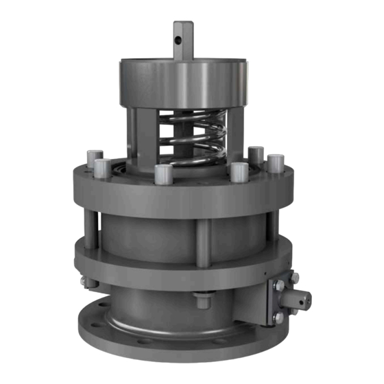
Visit midlandmfg.com for latest IOM revision and revision history. 2 Introduction The Midland A-547PL Series Modified Bottom Outlet Plug Valves are cavity free, corrosion-resistant devices designed for the containment of product in tank cars requiring superior product containment. High-quality steel construction with an optional integrated steam jacket •... - Page 7 Manual content is subject to change. Visit midlandmfg.com for latest IOM revision and revision history. Figure 2-2 A-547PL Dimensions (Section B-B) Figure 2-3 A-547PL Dimensions (Top View) A-547PL, Rev. 1 Page 7 of 34...
-
Page 8: Component Identification And Parts Listings
Manual content is subject to change. Visit midlandmfg.com for latest IOM revision and revision history. Component Identification and Parts Listings A-547PL-02-MO-S01 ITEM QTY. PART NAME MATERIAL PART NO. TOP GUIDE STAINLESS STEEL 547PL-1-MO SHAFT STAINLESS STEEL 547PL-22-SS PLUG ASSEMBLY STAINLESS STEEL 547PL-3-MO BODY STAINLESS STEEL... - Page 9 Manual content is subject to change. Visit midlandmfg.com for latest IOM revision and revision history. Figure 2-4 A-547PL Component Identification (Section A-A) Figure 2-5 A-547PL Component Identification (Section B-B) A-547PL, Rev. 1 Page 9 of 34...
-
Page 10: Operating Procedure
Manual content is subject to change. Visit midlandmfg.com for latest IOM revision and revision history. 3 Operating Procedure Opening the Valve 3.1.1 Conform with all applicable TC, AAR, and DOT regulations (Parts 173.31, 174.67, Pamphlet 34, etc.) CAUTION: When loading or unloading, the vacuum relief valve’s proper orientation must be verified, and the vent valve or manway cover opened to avoid either compressing air in loading, or drawing a vacuum when unloading. -
Page 11: Valve Installation
Manual content is subject to change. Visit midlandmfg.com for latest IOM revision and revision history. 4 Valve Installation Prior to installation, ensure that the valve remains clean and the gasket-sealing surfaces are not damaged. Installation Procedure and Required Tools SAE Wrench Component(s)/Description 3/4”... -
Page 12: Leak Inspection
Manual content is subject to change. Visit midlandmfg.com for latest IOM revision and revision history. Leak Inspection 4.2.1 Test all newly installed valves to conform to car-owner specifications. No leaks should be present. 4.2.2 Special Inspection Considerations 4.2.2.1 Previous procedures may not cover all conditions encountered in the field. Therefore, it is the responsibility of the repair agency to obtain approval from Midland for inspection, evaluation, repair and maintenance procedures not covered herein. -
Page 13: Valve Qualification
Manual content is subject to change. Visit midlandmfg.com for latest IOM revision and revision history. 5 Valve Qualification NOTICE: To ensure best practice and consistency of your qualification procedure, O-rings, gaskets and wire seals should always be replaced. Nuts, washers and studs must be closely inspected before re-use or replaced regularly. NOTICE Valve components such as the top guide, stem, retainer, body and spring must be thoroughly inspected. - Page 14 Manual content is subject to change. Visit midlandmfg.com for latest IOM revision and revision history. 5.2.2 Remove four nuts (item 41) and lockwashers (item 38) from the body studs (item 32). TIP: Use a 1” wrench to remove nuts (item 41). Figure 5-2 Remove Nuts and Lockwashers 5.2.3...
- Page 15 Manual content is subject to change. Visit midlandmfg.com for latest IOM revision and revision history. 5.2.8 Remove the top guide (item 1) and the spring (item 5) from the body (item 4). Figure 5-6 Remove Top Guide and Spring 5.2.9 To complete the top section of the valve disassembly, remove the plug assembly with O-rings and wiper (items 3, 10, 11 and 14) from the body (item 4) and remove the O-rings and wiper.
- Page 16 Manual content is subject to change. Visit midlandmfg.com for latest IOM revision and revision history. 5.2.12 Remove cam lever assembly (items 15 and 6) and remove the pin (item 35) to remove the retainer cover assembly (item 6) from the cam lever (item 15).
- Page 17 Manual content is subject to change. Visit midlandmfg.com for latest IOM revision and revision history. 5.2.16 Remove the retainer ring (item 18) from the shaft (item 2). TIP: Use a small flat-head screw driver to pry retainer ring (item 18) loose.
- Page 18 Manual content is subject to change. Visit midlandmfg.com for latest IOM revision and revision history. 5.2.20 From the shaft (item 2), remove the packing bushing (item 20) and O-rings (item 12 and 13). TIP: Use non-scratching tool to remove O-rings. Figure 5-18 Remove Packing Bushing 5.2.21...
-
Page 19: Component Inspection
Manual content is subject to change. Visit midlandmfg.com for latest IOM revision and revision history. Component Inspection Key components must be thoroughly inspected during the qualification process. These components include the top guide, shaft, retainer, valve body, spring and plug assembly. Top Guide (item 1) Spring (item 5) Plug Assembly (item 3) - Page 20 Manual content is subject to change. Visit midlandmfg.com for latest IOM revision and revision history. NOTICE: Without consent from the valve manufacturer or car owner, repair work is limited to cleaning and polishing. See AAR M1002, Paragraph A3.11.1 of the Tank-Car Specifications. NOTICE WARNING: Machining Not Allowed.
- Page 21 Manual content is subject to change. Visit midlandmfg.com for latest IOM revision and revision history. 5.3.4 Spring Inspection Visually inspect the spring (item 5). The spring should be free of corrosion, nicks, dents, scratches and pits. If any defects are found, the part is rejectable and should be replaced. Figure 5-25 Inspect Spring 5.3.5 Plug Assembly Inspection...
- Page 22 Manual content is subject to change. Visit midlandmfg.com for latest IOM revision and revision history. 5.3.8 Body Inspection Visually inspect the body (item 4) paying close attention to two O-ring grooves and to the valve seating area. The body should be free of corrosion, nicks, dents, scratches and pits.
- Page 23 Manual content is subject to change. Visit midlandmfg.com for latest IOM revision and revision history. 5.3.12 O-Ring and Gaskets Inspection O-rings (items 10, 11, 12, 13, 33) and soft seals (items 21 and 23) must be replaced at the time of the periodic valve retest and when the valve is disassembled.
-
Page 24: Valve Reassembly And Required Tools
Manual content is subject to change. Visit midlandmfg.com for latest IOM revision and revision history. Valve Reassembly and Required Tools SAE Wrenches Component(s)/Description Item # 7/16” Socket Wrench Retainer Bolts 26, 25 1” Wrench Nuts 5/8” Wrench Cam Bolt Other Tools, Supplies, and Equipment: Hammer/Pin Pusher Cam Assembly Pin Flat-Head Screw Driver... - Page 25 Manual content is subject to change. Visit midlandmfg.com for latest IOM revision and revision history. CAUTION: Mounting Interference. DO NOT paint the sealing surfaces of the valve that will contact the manway’s cover-plate surfaces or valve cracking may result. CAUTION 5.4.1 Install the seat O-ring (item 10), the bore O-ring (item 11), and the wiper ring (item 14) onto the plug assembly (Item 3).
- Page 26 Manual content is subject to change. Visit midlandmfg.com for latest IOM revision and revision history. 5.4.4 Into the shaft (item 2), install one packing bushing assembly (items 12, 13 and 20). Figure 5-36 Install Packing Bushing 5.4.5 Insert the shaft assembly through the open end of the base, through the retaining ring (item 18) and the cam (item 16), and into the bushing assembly (items 12, 13 and 20)
- Page 27 Manual content is subject to change. Visit midlandmfg.com for latest IOM revision and revision history. 5.4.8 Repeat steps 5.4.7 and 5.4.8 for the other end of the shaft/base assembly. Figure 5-40 Install Packing Ring, Packing Set, Packing Flange and Packing Bolts 5.4.9 Rotate the shaft (item 2) to locate the hole in the cam (item 16) for the assembly pin (item 29).
- Page 28 Manual content is subject to change. Visit midlandmfg.com for latest IOM revision and revision history. 5.4.12 Install the base O-ring (item 33) onto the adaptor flange (item 40). Figure 5-44 Install O-Ring on Adapter Flange and Place in Body 5.4.13 Put in-place the eight (x8) body bolts with lockwashers (Items 36 and 37) into the body (Item 4).
- Page 29 Manual content is subject to change. Visit midlandmfg.com for latest IOM revision and revision history. 5.4.16 Install base O-ring (Item 33) onto body/flange assembly. Figure 5-48 Install O-Ring onto Body 5.4.17 Secure base/flange/body assembly together by first threading on and hand tightening the four (x4) nuts (item 41) with lockwashers (item 38).
- Page 30 Manual content is subject to change. Visit midlandmfg.com for latest IOM revision and revision history. 5.4.21 Place the spring (item 5) in the body (item 4) on top of the plug assembly (item 3). Figure 5-52 Install Spring 5.4.22 Install the top guide (item 1) on top of the spring and place assembly in a press to compress the spring and top guide.
-
Page 31: Testing Process
Manual content is subject to change. Visit midlandmfg.com for latest IOM revision and revision history. Testing Process CAUTION: Safety Protection. Wear appropriate safety glasses or face shield and protective clothing when conducting this procedure. Valve testing involves high-velocity air and water flow that can cause injury. -
Page 32: Routine Maintenance
Manual content is subject to change. Visit midlandmfg.com for latest IOM revision and revision history. 6 Routine Maintenance NOTICE: Routine Maintenance involves valve inspection and component replacement for valves in- service on tank cars in accordance to the car owner’s standard maintenance program to ensure the valve performs the intended function without failure until the next qualification, or for the design life. -
Page 33: Shaft Packing Gland Leakage
Manual content is subject to change. Visit midlandmfg.com for latest IOM revision and revision history. Shaft Packing Gland Leakage NOTICE: It is necessary to remove the lower-half of the valve to repack the packing gland. Follow the procedure in 6.4 Leakage Through the Valve for steps 5.4.1 through 5.4.9. NOTICE 6.2.1 Note the orientation of the valve handle. - Page 34 © Copyright 2021, OPW. Printed in USA. © 2021 Delaware Capital Formation, Inc. All Rights Reserved.
Need help?
Do you have a question about the Midland A-547PL Series and is the answer not in the manual?
Questions and answers